SECTION 501-03: Body Closures
| 2014 Flex Workshop Manual
|
DESCRIPTION AND OPERATION
| Procedure revision date: 05/02/2013
|
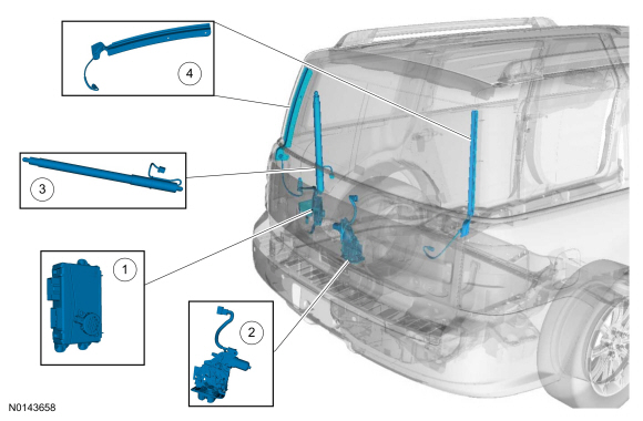
Component Location

| Item | Description |
|---|---|
| 1 | LTM |
| 2 | Power Liftgate Latch |
| 3 | Power Liftgate Motor |
| 4 | Pinch Strip (2 required) |
Overview
The power liftgate feature allows power opening or closing of the liftgate by using any of the following:
System Operation

Network Message Chart
LTM Network Input Messages
| Broadcast Message | Originating Module | Message Purpose |
|---|---|---|
| Power liftgate mode command | BCM | Used by the LTM to prevent the power closing and power open functions from operating when using the rear power liftgate switch and the liftgate release switch (the liftgate latch still releases when using the liftgate release switch). |
| RFA power liftgate open/close request | RFA module | Used by the LTM to either open or close the power liftgate. The RFA module sends this message to the LTM when there is a liftgate IA or RKE request. This message is only used on vehicles equipped with IA |
| Ignition switch position | BCM | Used by the LTM to halt the power liftgate operation when the ignition is in the start position. Once the ignition is out of the start position, the power liftgate operation resumes. |
| Selector lever (PRNDL) status | BCM | Used by the LTM to inhibit power liftgate operation if the transmission is not in PARK. |
| Vehicle speed | BCM | Used by the LTM to inhibit power liftgate operation if the vehicle speed is greater than 5 kmh (3.1 mph). |
Power Liftgate
NOTE: The power liftgate full open position is learned by the LTM during the power liftgate initialization.
The power liftgate power open operation begins when:
Once the LTM receives an open request, the power liftgate opens by carrying out the following:
The power liftgate power close operation begins when:
Once the LTM receives a close request, the power liftgate closes by carrying out the following:
If any of the power liftgate switches or the button on the RKE transmitter is pressed during a power close, the liftgate stops and holds its position.
NOTE: The power liftgate may not operate correctly under the following conditions:
If any of these conditions have occurred, the power liftgate must be re-initialized.
Power Liftgate Function Disable Feature
Using the message center settings, the power liftgate function can be disabled for the rear power liftgate switch and the liftgate release switch. When disabled, pressing the liftgate release switch releases the liftgate latch, however the liftgate does not power open. If the rear power liftgate switch is pressed with the liftgate open, the chime sounds, however the liftgate does not power close.
Liftgate Latch Manual Release
In the event of an electrical failure with the power liftgate system, the liftgate can still be opened. Refer to Liftgate Latch Manual Release in Section 501-14A .
Component Description
Front Power Liftgate Switch
The front power liftgate switch (located on the instrument panel) is a momentary contact switch that routes the voltage signal to ground from the LTM when pressed. Pressing this switch either opens, closes or stops the motion of the power liftgate.
Rear Power Liftgate Switch
The rear power liftgate switch (located on the rear quarter trim panel) is a momentary contact switch that routes the voltage signal to ground from the LTM when pressed. Pressing this switch closes the power liftgate (if set to enabled in the message center). The power liftgate does not open or release the latch from the rear power liftgate switch.
Liftgate Release Switch
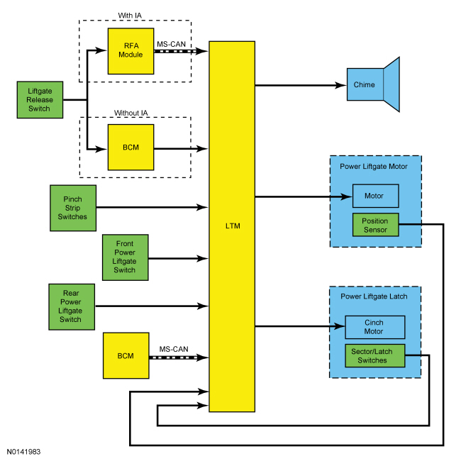
The liftgate release switch is a momentary contact switch that routes the voltage signal to ground from the BCM (without IA ) or the RFA module (with IA ).
When the liftgate switch is pressed, the BCM sends a signal to the LTM over a hardwired circuit which opens or stops the motion of the liftgate. The doors must be electronically unlocked before the BCM sends the signal to the LTM .
If the doors were not previously electronically unlocked when the liftgate switch is pressed, the RFA module activates the liftgate IA feature. If the RFA module detects a programmed IA key, the RFA module sends a signal over the MS-CAN to the LTM to open the liftgate. Any subsequent presses of the switch stops the motion or opens the liftgate.
If the doors were previously electronically unlocked when the liftgate switch is pressed, the RFA module sends a signal to the LTM over a hardwired circuit which opens or stops the motion of the liftgate.
Pinch Strip Switch
The power liftgate pinch strips are membrane-style switches. When the pinch strip is compressed, the contacts inside the switch make contact and provide a signal to the LTM to indicate an obstacle is present and prevent the liftgate from closing. When the pinch strip is not compressed, it has an approximate resistance of 5,700–6,700 ohms. When the pinch strip is compressed, it has an approximate resistance of 0–200 ohms.
Power Liftgate Chime
The power liftgate chime provides audible warnings to the operator. The power liftgate chime speaker is part of the power liftgate motor and not serviceable separately.
The power liftgate feature sounds an audible chime for 3 seconds when:
The power liftgate feature sounds an audible chime for 1 second when there is an open/close request and:
Power Liftgate Latch
The power liftgate latch is responsible for latching, unlatching, and cinching the liftgate. The power liftgate latch contains the unlatch/cinching motor, detent switch, forkbolt primary and secondary switches, and the sector gear switches.
The latch uses a bi-directional motor to accomplish both unlatch and cinch operations. The motor is driven in one direction to cinch and in the opposite direction to unlatch. During a cinch operation, power is supplied to the unlatch/cinching motor by the LTM when the secondary latch position is reached during a power close operation. When the motor activates, it pulls the liftgate into the primary latch position. The LTM removes power from the unlatch/cinching motor when the primary latch position is reached. During an unlatch operation, power is supplied to the unlatch/cinching motor by the LTM when a valid open command is received.
The power liftgate detent switch and forkbolt primary and secondary switches provide inputs to the LTM to determine liftgate latch position. The liftgate is in the primary position when the liftgate is in the full closed position. The liftgate is in the unlatch position when the liftgate is open and completely out of the striker. The LTM receives inputs from the power liftgate detent switch, forkbolt primary and secondary switches in the following manner:
Latch Switch States
| Latch Position | Detent Switch | Forkbolt Primary Switch | Forkbolt Secondary Switch |
|---|---|---|---|
| Fully unlatched | Open | Closed | Closed |
| Secondary | Closed | Closed | Open |
| Primary | Closed | Open | Open |
The sector gear switches open and close to provide input to the LTM to determine the position of the sector gear. The sector gear is part of the latch assembly. It is driven by the latch motor and in turn drives the latch mechanism. During a release operation, the LTM deactivates the unlatch/cinching motor once the end of travel is reached. After a release operation, the LTM keeps the latch released until the gate moves away from the vehicle. The LTM then reverses the direction of the unlatch/cinching motor until the sector gear switches indicate the sector gear has returned to the neutral position. Refer to the following table for sector gear switch states:
Sector Gear Switch States
| Sector Gear Position | Sector Gear Open Switch | Sector Gear Close Switch |
|---|---|---|
| End of travel | Closed | Closed |
| Release | Open | Closed |
| Cinch | Closed | Open |
| Neutral | Open | Open |
Power Liftgate Motor
The power liftgate motor is responsible for raising and lowering the liftgate. The power liftgate motor is a bi-directional motor and contains a position sensor that provides input back to the LTM for liftgate position and velocity.
The LTM supplies a 5-volt reference voltage to the position sensor on a valid open command or anytime the liftgate is in the open position (up to 6 hours). The LTM constantly supplies the ground. The position sensor has 2 data lines that the LTM monitors to determine liftgate movement and position. The LTM uses the liftgate position information to determine which direction to power the liftgate (open or close) when a valid operation command is received. The movement is monitored to identify obstructions.
Liftgate/Trunk Module (LTM)
The LTM sends voltage signals to the front and rear power liftgate switches. When a switch is pressed, the signal is routed to ground, pulling the signal low and indicating a request to open or close the liftgate. The liftgate release switch and RKE inputs are dependent from other modules.
On vehicles without IA , the LTM monitors a voltage signal circuit from the BCM . The BCM sends a momentary 12-volt signal to the LTM when it receives a valid request from the liftgate release switch or an RKE transmitter.
On vehicles with IA , the LTM receives a message from the RFA module upon a valid request from the liftgate release switch or an RKE transmitter.
The LTM controls the opening and closing of the power liftgate based on the inputs it receives. Based on the inputs, it determines if conditions allow a power open or power close.
The BCM supplies battery logic power required for the software and internal switching operations. The BJB supplies the higher current power needed for the motor and latch operation.
The LTM does not require PMI when it is replaced.