SECTION 501-12: Instrument Panel and Console
| 2014 Flex Workshop Manual
|
REMOVAL AND INSTALLATION
| Procedure revision date: 05/02/2013
|
| Item | Part Number | Description |
|---|---|---|
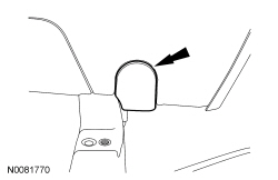
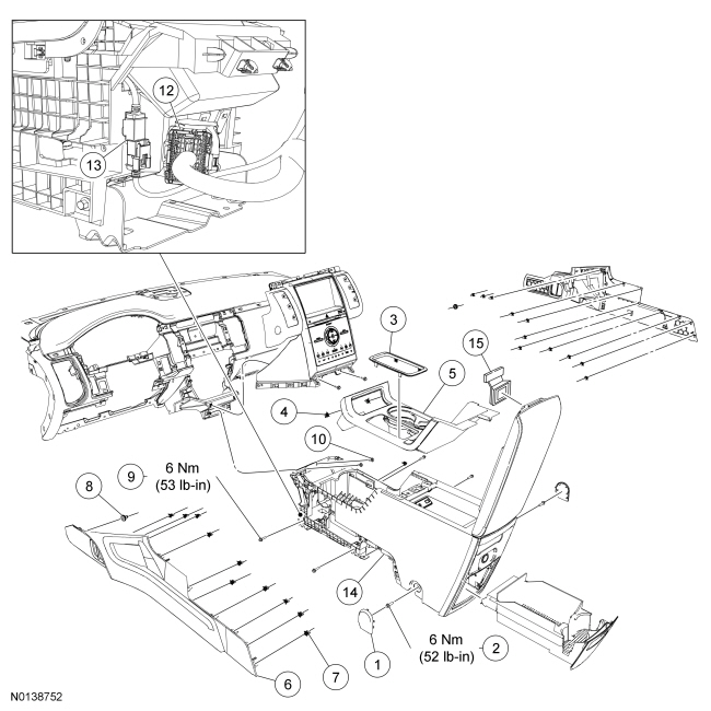
| 1 | 672A40 | Floor console rear lower bolt cover |
| 2 | W505424 | Front floor console rear lower bolt (2 required) |
| 3 | 7E391 | Selector lever trim ring |
| 4 | W710338 | Floor console finish panel retaining clip (3 required) |
| 5 | 045A76 | Floor console finish panel |
| 6 | 04608 RH/ 04609 LH | Floor console trim panel |
| 7 | W710338 | Floor console trim panel retaining clip (10 required) |
| 8 | W713267 | Floor console trim panel pin-type retainer (2 required) |
| 9 | W505424 | Front floor console lower bolt (4 required) |
| 10 | W707628 | Floor console upper bolt (2 required) |
| 11 | 13530 | Floor console rear storage compartment |
| 12 | — | Floor console electrical connector (part of 045A36) |
| 13 | 14D202 | Universal Serial Bus (USB) cable connection |
| 14 | 045A36 | Floor console |
| 15 | 7406064 | Latch |
Removal and Installation

NOTICE: Damage to the floor console may occur if cardboard is not used to remove the floor console trim panels.
NOTE: LH floor console trim panel shown, RH floor console trim panel similar.
Position a piece of cardboard between the LH and RH floor console trim panels and the floor console.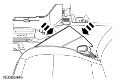
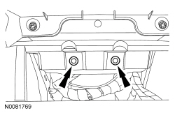
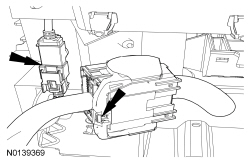
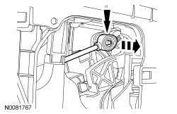
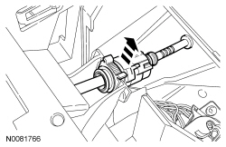
NOTE: During installation, verify the Restraints Control Module (RCM) connections are fully seated.
Remove the floor console.