SECTION 501-20B: Supplemental Restraint System
| 2014 Flex Workshop Manual
|
REMOVAL AND INSTALLATION
| Procedure revision date: 05/02/2013
|
Side Impact Sensor — Front Door
NOTE:
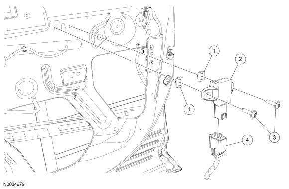
RH shown, LH similar.

| Item
| Part Number
| Description
| | 1
| W713617
| Insert nuts (2 required)
|
| 2
| 14B345
| Side impact sensor (pressure sensor)
|
| 3
| W705314
| Side impact sensor screws (2 required)
|
| 4
| —
| Side impact sensor electrical connector (part of 14630)
|
 WARNING: If a vehicle has been in a crash, inspect the restraints control module (RCM) and the impact sensor (if equipped) mounting areas for deformation. If damaged, restore the mounting areas to the original production configuration. A new RCM and sensors must be installed whether or not the airbags have deployed. Failure to follow these instructions may result in serious personal injury or death in a crash.
NOTE:
Always make sure the correct Supplemental Restraint System (SRS) component is being installed. Parts released for other vehicles may not be compatible even if they appear physically similar. Check the part number listed in the Ford Catalog Advantage™ or equivalent to make sure the correct component is being installed. If an incorrect
component is installed, DTCs may set.
NOTE:
The air bag warning indicator illuminates when the correct Restraints Control Module (RCM) fuse is removed and the ignition is ON.
NOTE:
The
must be fully operational and free of faults before releasing the vehicle to the customer.
- Depower the
. Refer to
Supplemental Restraint System (SRS) Depowering and Repowering
.
- Remove the front door trim panel. Refer to
Section 501-05
.
- Disconnect the side impact sensor electrical connector.
- Remove the 2 screws and side impact sensor.
NOTICE:
To prevent stripping the insert nuts, tighten the side impact sensor bolts only enough to retain the side impact sensor correctly.
To install, reverse the removal procedure.
- Inspect the insert nut for damage. If the insert nut is damaged, install a new insert.
- Repower the
. Refer to
Supplemental Restraint System (SRS) Depowering and Repowering
.
 WARNING: If a vehicle has been in a crash, inspect the restraints control module (RCM) and the impact sensor (if equipped) mounting areas for deformation. If damaged, restore the mounting areas to the original production configuration. A new RCM and sensors must be installed whether or not the airbags have deployed. Failure to follow these instructions may result in serious personal injury or death in a crash.
