SECTION 501-35: Body Repairs
| 2014 Flex Workshop Manual
|
REMOVAL AND INSTALLATION
| Procedure revision date: 05/02/2013
|
Inner Body Reinforcing Panels
General Equipment
| 3 Phase Inverter Spot Welder 254-00002
|
| Compuspot 700F Welder 190-50080
|
| I4 Inverter Spot Welder 254-00014
|
| Inverter Welder with MIG Welder 254-00015
|
Material
| Item
| Specification
|
|---|
Motorcraft® Metal Surface Prep
ZC-31-A
| —
|
Premium Undercoating
ValuGard™ VG101, VG101A (aerosol)
| —
|
Rust Inhibitor
ValuGard™ VG104, VG104A (aerosol)
| —
|
Motorcraft® Seam Sealer
TA-2
| —
|
Exploded View
 WARNING: Invisible ultraviolet and infrared rays emitted in welding can injure unprotected eyes and skin. Always use protection such as a welder's helmet with dark-colored filter lenses of the correct density. Electric welding will produce intense radiation, therefore, filter plate lenses of the deepest shade providing adequate visibility are recommended. It is strongly recommended that persons working in the weld area wear flash safety goggles. Also wear protective clothing. Failure to follow these instructions may result in serious personal injury.
 WARNING: Always wear protective equipment including eye protection with side shields, and a dust mask when sanding or grinding. Failure to follow these instructions may result in serious personal injury.
NOTE:
Outer panels removed for clarity.
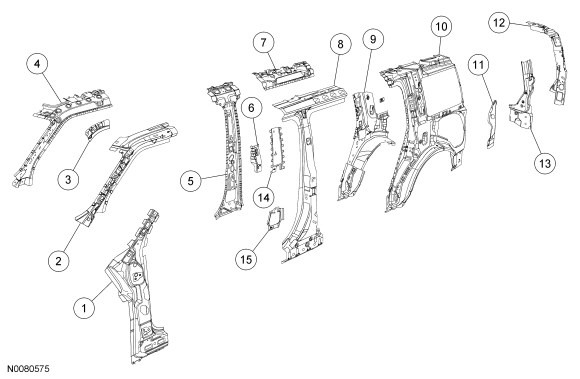
| Item
| Part Number
| Description
| | 1
| 02555 LH/ 02554 RH
| Front body pillar reinforcement assembly — Bake Hardened Steel (BH) 280 and mild steel
|
| 2
| 513A53 LH/ 513A52 RH
| Roof rail reinforcement — boron and High-Strength Low Alloy (HSLA) 350 steel
|
| 3
| —
| Reinforcement —
350 steel (part of 203A57 LH/ 203A56 RH)
|
| 4
| 203A57 LH/ 203A56 RH
| Door opening panel assembly —
350 steel
|
| 5
| 24359 LH/ 24358 RH
| Center body pillar inner reinforcement —
350 steel
|
| 6
| —
| Reinforcement —
250 steel (part of 24359 LH/ 24358 RH)
|
| 7
| —
| Reinforcement —
350 steel (part of 24359 LH/ 24358 RH)
|
| 8
| 24383 LH/ 24382 RH
| Center body pillar reinforcement —
350 and mild steel
|
| 9
| 28409 LH/ 28408 RH
| Body side panel rear reinforcement —
250 and mild steel
|
| 10
| 27865 LH/ 27864 RH
| Body side panel inner — mild steel
|
| 11
| 45115 LH/ 45114 RH
| Liftgate opening side drain trough — mild steel
|
| 12
| 41021 LH/ 41020 RH
| Rear corner pillar reinforcement assembly —
350 steel
|
| 13
| 45101 LH/ 45100 RH
| Liftgate opening trough assembly — mild steel
|
| 14
| 24557 LH/ 24556 RH
| Center body pillar reinforcement —
350 steel
|
| 15
| —
| Reinforcement —
350 steel (part of 24383 LH/ 24382 RH)
|
A-Pillar Inner Reinforcement
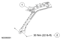
| Item
| Part Number
| Description
| | 1
| 203A57 LH/ 203A56 RH
| Door opening panel assembly
|
| 2
| W706246-S
| Door opening panel bolt (2 required per side)
|
Underbody — Front
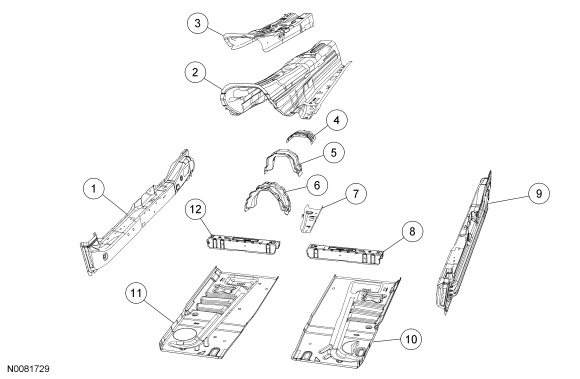
| Item
| Part Number
| Description
| | 1
| 10142
| Floor side member — Dual Phase Steel (DP) 600 steel
|
| 2
| 11170
| Floor tunnel — High-Strength Low Alloy (HSLA) 250 steel
|
| 3
| 111K36
| Floor tunnel reinforcement —
350 steel
|
| 4
| 111K37
| Floor tunnel reinforcement —
250 steel
|
| 5
| 111270
| Floor tunnel center reinforcement — mild steel
|
| 6
| 111A44
| Floor tunnel reinforcement — mild steel
|
| 7
| 10044
| Reinforcement —
250 steel
|
| 8
| 10776
| Floor crossmember —
350 steel
|
| 9
| 10143
| Floor side member —
600 steel
|
| 10
| 11141
| Floor pan — mild steel
|
| 11
| 11140
| Floor pan — mild steel
|
| 12
| 10776
| Floor crossmember —
350 steel
|
Underbody — Rear
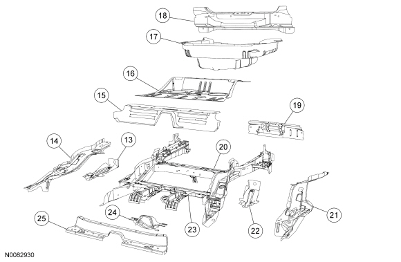
| Item
| Part Number
| Description
| | 13
| 102B90
| Plate — High-Strength Low Alloy (HSLA) 350 steel
|
| 14
| 10456
| Rear floor side upper member —
550 steel
|
| 15
| 112A84
| Center floor pan lower —
350 steel
|
| 16
| 11160A
| Center floor pan — mild steel
|
| 17
| 11218A
| Rear floor pan — mild steel
|
| 18
| 105552A
| Rear floor pan inner sill — mild steel
|
| 19
| 10700A
| Rear floor lower assembly —
350 steel
|
| 20
| 11215
| Rear floor crossmember and rail assembly —
350 and mild steel
|
| 21
| 10457
| Rear floor side upper member —
350 steel
|
| 22
| 102B91
| Plate —
350 steel
|
| 23
| 10780A
| Crossmember — Dual Phase Steel (DP) 600
|
| 24
| 106K02
| Crossmember —
250 steel
|
| 25
| 11644
| Front crossmember —
600 steel
|
Front Structure
NOTE:
Left side shown, right side similar.
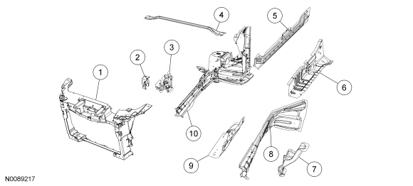
| Item
| Part Number
| Description
| | 1
| 16138
| Radiator support — magnesium
|
| 2
| 16138A
| Bracket — mild steel
|
| 3
| 108A27 LH/ 108A26 RH
| Reinforcement — mild steel
|
| 4
| 3C232
| Brace
|
| 5
| 10143 LH/ 10142 RH
| Rocker panel reinforcement — High-Strength Low Alloy (HSLA) 350 steel
|
| 6
| 16B045 LH/ 16B044 RH
| Fender reinforcement — mild steel
|
| 7
| 101A03 LH/ 101A02 RH
| Reinforcement — mild steel
|
| 8
| 16A045 LH/ 16A044 RH
| Outer rail and apron assembly — Dual Phase Steel (DP) 600,
350 and mild steel
|
| 9
| 16055 LH/ 16054 RH
| Fender apron — mild steel
|
| 10
| 10009 LH/ 10008 RH
| Front inner rail assembly —
600 and mild steel
|
 WARNING: Collision damage repair must conform to the instructions contained in this workshop manual. Replacement components must be new, genuine Ford Motor Company parts. Recycled, salvaged, aftermarket or reconditioned parts (including body parts, wheels or safety restraint components) are not authorized by Ford.
Departure from the instructions provided in this manual, including alternate repair methods or the use of substitute components, risks compromising crash safety. Failure to follow these instructions may adversely affect structural integrity and crash safety performance, which could result in serious personal injury to vehicle occupants in a crash.
 WARNING: On vehicles equipped with Safety Canopy® options, prior to carrying out any sectioning repairs near the roof line or sail panel areas of the vehicle, remove the Safety Canopy® module and related components. Failure to comply may result in accidental deployment or damage to the Safety Canopy®. Refer to
Section 501-20B
. Failure to follow these instructions may result in serious injury to technician or vehicle occupant(s).
 WARNING: Do not cut or grind body side components within 50 mm (1.96 in) of restraint anchoring points. Welding within 50 mm (1.96 in) of restraint anchoring points may result in incorrect operation of restraint devices. For additional restraints anchoring location information, refer to
Section 501-20A
and
Section 501-20B
. Failure to follow these instructions may result in serious injury to vehicle occupant(s).
NOTICE:
Sectioning procedures can only be carried out on the outer body side panel. No sectioning repairs can be carried out on inner reinforcement panels. Failure to follow these instructions may compromise the structural integrity of the vehicle.
NOTE:
Refer to the Ford Recommended Steel Repairability Matrix in the Specifications portion of this section for specific information regarding steel descriptions.
NOTE:
When it is necessary to carry out weld-bonding procedures, refer to
Weld-Bonding
in this section.
NOTE:
Observe prescribed welding procedures when carrying out any body side section repair. For additional information, refer to
Welding Precautions — Steel
in this section.
NOTE:
Factory spot welds may be substituted with either Squeeze-Type Resistance Spot Welding (STRW) welds or Metal Inert Gas (MIG) plug welds. Spot/plug welds should equal factory welds in both location and quantity. Do not place a new spot weld directly over an original weld location. Plug weld hole should equal 8 mm (0.31 in) diameter.
Remove the outer body sheet metal from the affected area prior to carrying out any reinforcing panel replacement. For additional information, refer to
Sectioning Guidelines
in this section.
- When welding overlapping surfaces or substrates, apply corrosion protection material between the surfaces prior to welding. When the surfaces have been welded, apply corrosion protection material to the exterior surfaces or substrates. For additional information, refer to
Restoring Corrosion Protection Following Repair
in this section.
- Corrosion protection needs to be restored whenever it is necessary to sand or grind through painted surfaces or E-coat, or when bare metal repairs are carried out. For additional information, refer to
Restoring Corrosion Protection Following Repair
in this section.
- Make sure horizontal joints and flanges are correctly sealed with seam sealer to prevent moisture intrusion. Water and moisture migrate to horizontal joints and corrosion tends to occur more rapidly in these areas. Clean metal surfaces with metal surface cleaner or equivalent before applying seam sealer.
- Proceed with the refinish process following Ford-approved paint recommendations.
 WARNING: Invisible ultraviolet and infrared rays emitted in welding can injure unprotected eyes and skin. Always use protection such as a welder's helmet with dark-colored filter lenses of the correct density. Electric welding will produce intense radiation, therefore, filter plate lenses of the deepest shade providing adequate visibility are recommended. It is strongly recommended that persons working in the weld area wear flash safety goggles. Also wear protective clothing. Failure to follow these instructions may result in serious personal injury.


