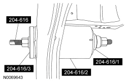
204-618

204-616
SECTION 502-00: Uni-Body, Subframe and Mounting System
| 2014 Flex Workshop Manual
|
REMOVAL AND INSTALLATION
| Procedure revision date: 05/02/2013
|
 | Remover/Installer, Rear Drive Unit (RDU) Bushing (65 mm)
204-618 |
 | Remover/Installer, Rear Drive Unit (RDU) Bushing (70 mm)
204-616 |
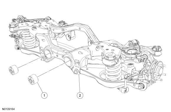
| Item | Part Number | Description |
|---|---|---|
| 1 | 4B425AA | Rear Drive Unit (RDU) bushing — rear bushings (2 required) |
| 2 | 5N354 | Rear subframe |
Removal
NOTE: There are 2 Rear Drive Unit (RDU) rear bushings in the rear subframe. This procedure shows how to remove one bushing. The procedure for the remaining RDU bushing is identical.
NOTE: The Rear Drive Unit (RDU) Bushing (65 mm) Remover/Installer 204-618/1 must be used to remove the bushing to make sure that it passes through the receiver cup.
NOTE: Make sure the Rear Drive Unit (RDU) Bushing (70 mm) Remover/Installer 204-616/2 is positioned with the larger opening toward the bushing to act as the receiver cup.
NOTE: Make sure the arrow on the Rear Drive Unit (RDU) Bushing (70 mm) Remover/Installer is pointed toward the rear subframe when removing the bushing.
Assemble the Rear Drive Unit (RDU) Bushing (65 mm) Remover/Installer and the Rear Drive Unit (RDU) Bushing (70 mm) Remover/Installer to the rear subframe and press out the bushing.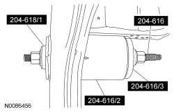
Installation
NOTE: There are 2 RDU rear bushings in the subframe. This procedure shows how to install one bushing. The procedure for the remaining RDU bushing is identical.
NOTE: Make sure the alignment marks on the Rear Drive Unit (RDU) Bushing (70 mm) Remover/Installer 204-616/2 are aligned with the anti-rotation tabs on the RDU bushing.
Install the RDU bushing into the Rear Drive Unit (RDU) Bushing (70 mm) Remover/Installer 204-616/2.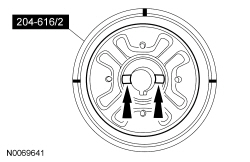
NOTE: Make sure the alignment marks are properly aligned on both the Rear Drive Unit (RDU) Bushing (70 mm) Remover/Installer 204-616/1 and Rear Drive Unit (RDU) Bushing (70 mm) Remover/Installer 204-616/2 and the anti-rotation tabs are properly seated in the Rear Drive Unit (RDU) Bushing (70 mm) Remover/Installer 204-616.
Install the Rear Drive Unit (RDU) Bushing (70 mm) Remover/Installer 204-616 onto the RDU bushing.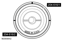
NOTE: Make sure the arrow on the Rear Drive Unit (RDU) Bushing (70 mm) Remover/Installer 204-616/2 is visible on the bottom and facing away from the subframe. The arrow must remain straight so that the bushings are correctly indexed into the subframe.
NOTE: When installing the RDU bushing, Rear Drive Unit (RDU) Bushing (70 mm) Remover/Installer 204-616/2 will fall away as the RDU bushing is installed into the subframe. The Rear Drive Unit (RDU) Bushing (70 mm) Remover/Installer does not control the depth of the bushing. The RDU bushing is fully seated when the Rear Drive Unit (RDU) Bushing (70 mm) Remover/Installer 204-616/3 and Rear Drive Unit (RDU) Bushing (70 mm) Remover/Installer 204-616/1 fall away from the subframe, do not continue to tighten the Rear Drive Unit (RDU) Bushing (70 mm) Remover/Installer.
Install the RDU bushing into the subframe.