SECTION 303-03: Engine Cooling
| 2014 Flex Workshop Manual
|
DESCRIPTION AND OPERATION
| Procedure revision date: 05/02/2013
|
NOTICE: The engine cooling system is filled with Motorcraft® Orange Antifreeze/Coolant. Always fill the cooling system with the manufacturer's specified coolant. Chemically flush the cooling system if a non-specified coolant has been used. Refer to Cooling System Flushing in this section. Failure to follow these instructions may damage the engine or cooling system.
NOTICE: Use Motorcraft® Orange Antifreeze/Coolant. Do not mix coolant types. Mixing coolant types degrades the coolant corrosion protection and may damage the engine or cooling system.
NOTICE: Do not use stop-leak style pellets/products as an additive in this engine cooling system. The addition of stop-leak style pellets/products can clog or damage the cooling system, resulting in degraded cooling system performance and/or failure.
NOTE: During normal vehicle operation, Motorcraft® Orange Antifreeze/Coolant may change color from orange to pink or light red. As long as the engine coolant is clear and uncontaminated, this color change does not indicate the engine coolant has degraded nor does it require the engine coolant to be drained, the system to be flushed, or the engine coolant to be replaced.
The cooling system components are the:

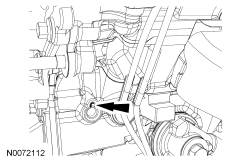
The coolant pump is located under the engine front cover mounted to the block. A weep hole is provided on the front left side of the engine behind the generator, adjacent to a 13.5 mm (0.531 in) cup plug. The plug and the weep hole create a reservoir for normal coolant seepage and evaporation. Every coolant pump will have some leakage past the dynamic mechanical seal. Dampness and crusting around the weep hole is acceptable and an expected result of normal engine operation. Address any coolant spray or leakage amounts large enough to puddle.
Engine coolant provides freeze protection, boil protection, cooling efficiency and corrosion protection to the engine and cooling components. In order to obtain these protections, maintain the engine coolant at the correct concentration and fluid level in the degas bottle.
When adding or topping off the engine coolant:
When refilling the engine coolant after a flush procedure, use a mixture of Motorcraft® Orange Antifreeze/Coolant Concentrated and distilled water to get to the desired concentration.
To maintain the integrity of the coolant and the cooling system:
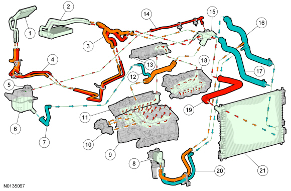
Coolant Flow Diagram — 3.5L Ti-VCT
NOTE: At 38°C (100°F) ambient temperature, green arrows indicate coolant temperature below 90°C (194°F), amber arrows indicate coolant temperature approximately 90°C (194°F), red arrows indicate coolant temperature above 90°C (194°F).

| Item | Part Number | Description |
|---|---|---|
| 1 | 18B539 | Auxiliary heater core |
| 2 | 18B539 | Heater core |
| 3 | 18663 | Heater hose assembly |
| 4 | 18B553 | Auxiliary heater hose assembly |
| 5 | 8101 | Pressure relief cap |
| 6 | 8A080 | Degas bottle |
| 7 | 8W005 | Degas bottle-to-coolant inlet pipe hose |
| 8 | 6A642 | Oil cooler |
| 9 | 6010 | Engine block |
| 10 | 8501 | Coolant pump |
| 11 | 6049 | Cylinder head — RH |
| 12 | 9N271 | Coolant pump inlet pipe |
| 13 | 9K461 | Lower intake manifold |
| 14 | 8B541 | Thermostat housing-to-degas bottle hose |
| 15 | 8A586 | Thermostat housing |
| 16 | 8B273 | Lower radiator hose (engines with an oil cooler) |
| 17 | 8B273 | Lower radiator hose (engines without an oil cooler) |
| 18 | 6050 | Cylinder head — LH |
| 19 | 8B274 | Upper radiator hose |
| 20 | 6A715 | Oil cooler coolant hoses |
| 21 | 8005 | Radiator |
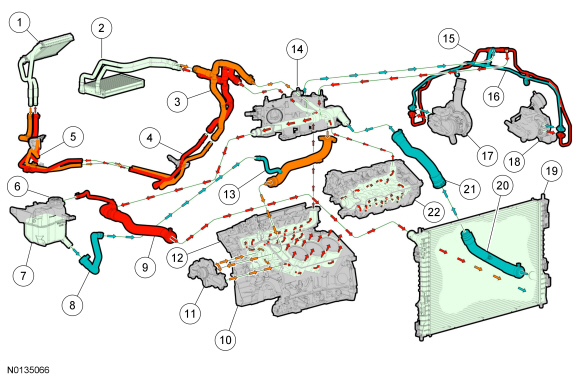
Coolant Flow Diagram — 3.5L Gasoline Turbocharged Direct Injection (GTDI)
NOTE: At 38°C (100°F) ambient temperature, green arrows indicate coolant temperature below 90°C (194°F), amber arrows indicate coolant temperature approximately 90°C (194°F), red arrows indicate coolant temperature above 90°C (194°F).

| Item | Part Number | Description |
|---|---|---|
| 1 | 18B539 | Auxiliary heater core |
| 2 | 18B539 | Heater core |
| 3 | 18663 | Heater hose assembly |
| 4 | 18663 | Auxiliary heater tube assembly |
| 5 | 18696 | Auxiliary heater hose assembly |
| 6 | 8101 | Pressure relief cap |
| 7 | 8A080 | Degas bottle |
| 8 | 8W005 | Degas bottle-to-coolant inlet pipe hose |
| 9 | 8B274 | Upper radiator hose |
| 10 | 6010 | Engine block |
| 11 | 8501 | Coolant pump |
| 12 | 6049 | Cylinder head — RH |
| 13 | 9N271 | Coolant inlet pipe |
| 14 | 9S455 | Intake manifold |
| 15 | 8K579 | Turbocharger coolant outlet tubes |
| 16 | 9V427 | Turbocharger coolant inlet tubes |
| 17 | 6K682 | RH turbocharger |
| 18 | 9G438 | LH turbocharger |
| 19 | 8005 | Radiator |
| 20 | 8B273 | Lower radiator hose |
| 21 | 8B273 | Lower radiator hose |
| 22 | 6050 | Cylinder head — LH |