SECTION 303-04C: Fuel Charging and Controls — Turbocharger, 3.5L GTDI
| 2014 Flex Workshop Manual
|
DESCRIPTION AND OPERATION
| Procedure revision date: 05/02/2013
|
NOTICE: Whenever turbocharger air intake system components are removed, always cover open ports to protect from debris. It is important that no foreign material enter the system. The turbocharger compressor vanes are susceptible to damage from even small particles. All components should be inspected and cleaned, if necessary, prior to installation or reassembly.
The turbocharger assembly consists of the following components:
The turbocharger is an exhaust-driven centrifugal air compressor. Its purpose is to increase power output by supplying compressed air to the engine. The internal components are oil, coolant and air cooled. Engine oil and coolant are circulated through the center housing which acts as a heat barrier between the "hot" turbine and the "cold" compressor. Bearings are sleeve type and lubricated by engine oil. Oil is circulated to the turbocharger center housing and returned to the sump through an oil drain in the center housing.
Expanding exhaust gases drive the turbine shaft assembly to speeds up to 200,000 rpm. Filtered air entering the compressor side of the turbocharger is compressed and delivered through a Charge Air Cooler (CAC). The very hot compressed air is cooled, then continues on to fill the intake manifold at a higher pressure than atmospheric pressure. Because considerably more air is forced into the intake manifold, the results are increased power, fuel efficiency and the ability to maintain power at higher altitudes.
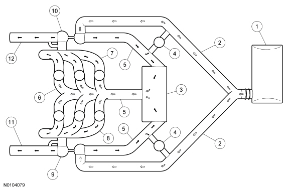
The EcoBoost twin turbochargers are used in a parallel arrangement with one turbocharger connected to each cylinder bank. This configuration improves engine responsiveness due to the reduced interia of 2 small turbochargers. This also leads to an improved turbocharger package and better utilization of heat energy from the compact exhaust manifolds. The compact design of the system allows the catalysts to be located very close to the turbocharger outlet for improved emissions.
NOTE: Black arrows indicate hot, white arrows indicate cold.

| Item | Part Number | Description |
|---|---|---|
| 1 | 9C662 | Air Cleaner (ACL) |
| 2 | 9B659 | ACL outlet pipe |
| 3 | 6K775 | Charge Air Cooler (CAC) |
| 4 | 9U465 | Turbocharger bypass valve |
| 5 | 6C646 | CAC tube |
| 6 | 9424 | Intake manifold |
| 7 | 9428 | RH exhaust manifold |
| 8 | 9429 | LH exhaust manifold |
| 9 | 9G438 | LH turbocharger |
| 10 | 6K682 | RH turbocharger |
| 11 | 5G203 | LH exhaust flexible pipe |
| 12 | 5G203 | RH exhaust flexible pipe |