SECTION 303-04C: Fuel Charging and Controls — Turbocharger, 3.5L GTDI
| 2014 Flex Workshop Manual
|
REMOVAL AND INSTALLATION
| Procedure revision date: 05/02/2013
|
Turbocharger — LH
Material
| Item
| Specification
|
|---|
Motorcraft® SAE 5W-30 Premium Synthetic Blend Motor Oil (US); Motorcraft® SAE 5W-30 Super Premium Motor Oil (Canada)
XO-5W30-QSP (US); CXO-5W30-LSP12 (Canada)
| WSS-M2C946-A
|
Removal
NOTICE:
Whenever turbocharger air intake system components are removed, always cover open ports to protect from debris. It is important that no foreign material enter the system. The turbocharger compressor vanes are susceptible to damage from even small particles. All components should be inspected and cleaned, if necessary, prior to installation or reassembly.
- With the vehicle in NEUTRAL, position it on a hoist. Refer to
Section 100-02
.
- Remove the Air Cleaner (ACL) assembly. Refer to
Section 303-12
.
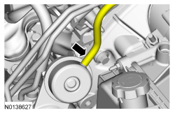
- Disconnect the wastegate control valve hose from the LH turbocharger assembly.
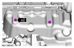
- Remove the 2 bolts from the top of the LH exhaust manifold heat shield.
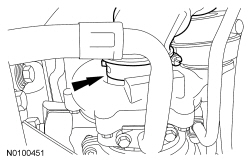
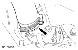
- Loosen the clamp and remove the LH turbocharger intake tube from the turbocharger.
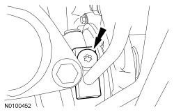
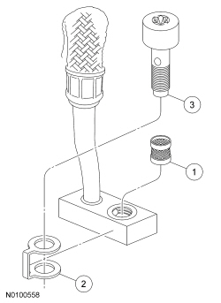
- Remove the LH turbocharger oil supply tube bolt and sealing washer.
- Discard the sealing washer and oil supply tube filter.
- Drain the cooling system. Refer to
Section 303-03
.
- Remove the LH catalytic converter. Refer to
Section 309-00
.
- Remove the bottom bolt and the LH exhaust manifold heat shield.
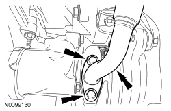
- Remove the 2 LH oil return tube-to-turbocharger bolts.
- Remove and discard the gasket.
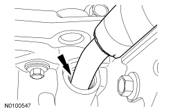
- Remove the LH turbocharger oil return tube from the oil pan.
- Discard the 2 O-ring seals.
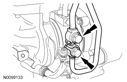
- Remove the 2 coolant tube banjo bolts and the LH turbocharger coolant tubes.
- Discard the sealing washers.
- Loosen the clamp and remove the LH
tube from the LH turbocharger.
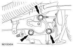
- Remove the 3 exhaust manifold-to-LH turbocharger bolts.
- Discard the gasket and bolts.
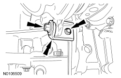
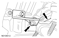
- Remove the 2 bolts and the lower LH turbocharger-to-cylinder block bracket.
- Remove the upper LH turbocharger bracket-to-turbocharger bolt and the turbocharger assembly.
Installation
NOTICE:
The upper LH turbocharger bracket bolt must be loosened in order to perform the tightening sequence or damage to the turbocharger may occur.
Loosen the upper LH turbocharger bracket bolt.
- Install a new LH exhaust manifold-to-turbocharger gasket.
- Install the turbocharger assembly and install upper LH turbocharger bracket-to-turbocharger bolt.
- Do not tighten the bolts at this time.
- Install the lower LH turbocharger-to-cylinder block bracket and the 2 bolts.
- Do not tighten the bolts at this time.
- Install the 3 new LH exhaust manifold-to-turbocharger bolts.
- Tighten to 45 Nm (33 lb-ft).
NOTICE:
The next 4 steps must be performed in the order written or damage to the turbocharger may occur.
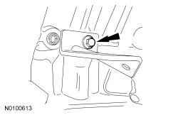
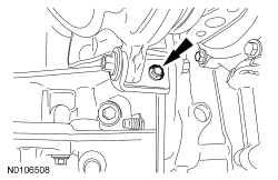
- Tighten the upper LH turbocharger bracket-to-turbocharger bolt.
- Tighten to 19 Nm (168 lb-in).
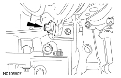
- Tighten the upper LH turbocharger bracket-to-cylinder block bolt.
- Tighten to 25 Nm (18 lb-ft).
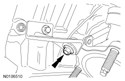
- Tighten the lower LH turbocharger bracket-to-turbocharger bolt.
- Tighten to 19 Nm (168 lb-in).
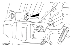
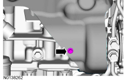
- Tighten the lower LH turbocharger bracket-to-cylinder block bolt.
- Tighten to 11 Nm (97 lb-in).
NOTE:
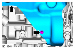
Align the index marks for the LH
tube.
Install the LH
tube on the LH turbocharger and tighten the clamp.
- Tighten to 5 Nm (44 lb-in).
- Using 2 new sealing washers, install the 2 coolant tube banjo bolts.
- Tighten to 40 Nm (30 lb-ft).
NOTE:
Lubricate the oil pan bore with clean engine oil.
Using 2 new O-ring seals, install the LH turbocharger oil return tube to the oil pan.
- Using a new gasket, install the LH turbocharger oil return tube and the 2 bolts.
- Tighten to 10 Nm (89 lb-in).
NOTE:
Align the marks for the LH turbocharger intake tube.
Install LH turbocharger intake tube and tighten the clamp.
- Tighten to 5 Nm (44 lb-in).
- Install the oil supply tube filter, washer and bolt.
- Install the new oil supply tube filter in the oil supply tube block.
- Slide the new washer onto the oil supply tube block.
- Install the bolt into the oil supply tube block.
- Install the LH turbocharger oil supply tube.
- Tighten to 40 Nm (30 lb-ft).
NOTE:
Make sure the turbocharger wastegate regulating valve hose does not contact the exhaust manifold heat shield.
Connect the wastegate control valve hose to the LH turbocharger assembly.
- Install the LH exhaust manifold heat shield and the bottom bolt.
- Do not tighten the bolts at this time.
- Install the 2 top LH exhaust manifold heat shield bolts.
- Tighten to 12 Nm (106 lb-in).
- Tighten the LH exhaust manifold heat shield bottom bolt.
- Tighten to 12 Nm (106 lb-in).
- Install the LH catalytic converter. Refer to
Section 309-00
.
- Fill and bleed the cooling system. Refer to
Section 303-03
.
- Install the
assembly. Refer to
Section 303-12
.
