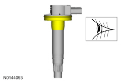
 WARNING: Before beginning any service procedure in this section, refer to Safety Warnings in
Section 100-00
. Failure to follow this instruction may result in serious personal injury.
SECTION 303-07B: Engine Ignition — 3.5L GTDI
| 2014 Flex Workshop Manual
|
REMOVAL AND INSTALLATION
| Procedure revision date: 05/02/2013
|
| Item | Specification |
|---|---|
| Motorcraft® Silicone Brake Caliper Grease and Dielectric Compound
XG-3-A | ESE-M1C171-A |
Removal and Installation
 WARNING: Before beginning any service procedure in this section, refer to Safety Warnings in
Section 100-00
. Failure to follow this instruction may result in serious personal injury.
NOTE: Removal steps in this procedure may contain installation details.
LH
side
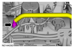
NOTE: When removing or installing the fuel injection pump noise insulator, spreading the openings will reduce the risk of damage.
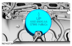
RH
side
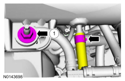
NOTE: When installing, align the index marks.
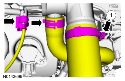
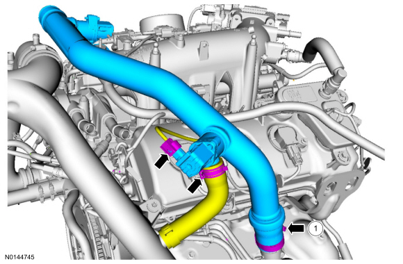
NOTE: When installing, align the index marks.
Both sides
NOTE: Use compressed air to remove any foreign material from the ignition coil-on-plugs and surrounding area before removing the ignition coil-on-plugs.
NOTE: When removing the ignition coil-on-plugs, a slight twisting motion will break the seal and ease removal.
NOTE: When installing the ignition coil-on-plugs, apply a small amount of silicone brake caliper grease and dielectric compound to the inside of the ignition coil-on-plug boots before installation. Material: Silicone Brake Caliper Grease and Dielectric Compound XG-3-A.
Tighten in the following 2 stages.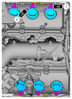
Installation
