
205-832

205-D070 (D93P-1175-B) or equivalent

100-001 (T50T-100-A)
SECTION 205-04: Front Drive Halfshafts
| 2014 Flex Workshop Manual
|
REMOVAL AND INSTALLATION
| Procedure revision date: 05/02/2013
|
 | Halfshaft Remover
205-832 |
 | Remover, Front Wheel Hub
205-D070 (D93P-1175-B) or equivalent |
 | Slide Hammer
100-001 (T50T-100-A) |
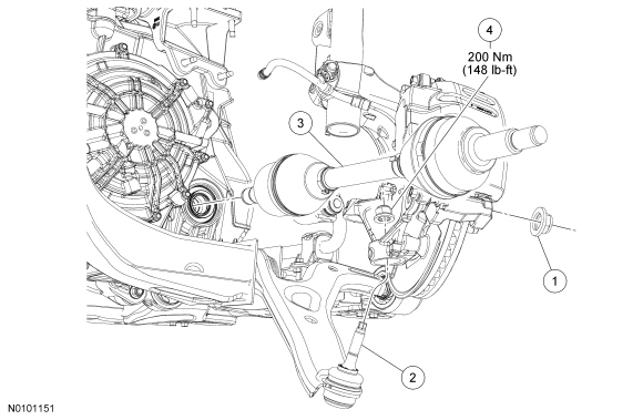
| Item | Part Number | Description |
|---|---|---|
| 1 | W712435 | Wheel hub nut |
| 2 | 3051LH | Lower ball joint |
| 3 | 3B437 | Halfshaft assembly |
| 4 | W710015 | Lower ball joint nut |
Removal
NOTE: Apply the brake to keep the halfshaft from rotating.
Remove the wheel hub nut.NOTICE: Use care when releasing the lower arm and knuckle into the resting position or damage to the ball joint seal or Constant Velocity (CV) boot may occur.
NOTE: Use the hex-holding feature to prevent the stud from turning while removing the nut.
Remove and discard the lower ball joint nut.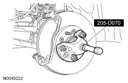
NOTICE: The sharp edges on the stub shaft splines can slice or puncture the oil seal. Use care when inserting the stub shaft into the transmission or damage to the component may occur.
Using the Slide Hammer and Halfshaft Remover, remove the halfshaft from the transmission.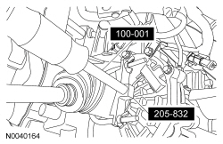
Installation
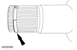
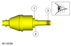
NOTICE: The circlips are unique in size and shape for each shaft. Make sure to use the specified circlip for the application or vehicle damage may occur.
Install the correct new circlip on the inboard stub shaft.
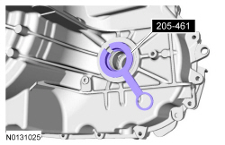
NOTE: Remove the seal protector before the halfshaft is installed completely.
NOTE: After insertion, pull the halfshaft inner end to make sure the circlip is locked.
Push the stub shaft into the transmission so the circlip locks into the differential side gear.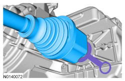
NOTICE: Do not tighten the wheel hub nut with the vehicle on the ground. The nut must be tightened to specification before the vehicle is lowered onto the wheels. Wheel bearing damage will occur if the wheel bearing is loaded with the weight of the vehicle applied.
NOTE: Apply the brake to keep the halfshaft from rotating.
Using the previously removed wheel hub nut, seat the halfshaft.NOTICE: The wheel hub nut contains a one-time locking chemical that is activated by the heat created when it is tightened. Install and tighten the new wheel hub nut to specification within 5 minutes of starting it on the threads. Always install a new wheel hub nut after loosening or when not tightened within the specified time or damage to the components can occur.
NOTE: Apply the brake to keep the halfshaft from rotating.
Install a new wheel hub nut.