
205-816

205-D070 (D93P-1175-B) or equivalent
SECTION 205-05: Rear Drive Halfshafts
| 2014 Flex Workshop Manual
|
REMOVAL AND INSTALLATION
| Procedure revision date: 05/02/2013
|
 | Axle Seal Protector
205-816 |
 | Front Hub Remover
205-D070 (D93P-1175-B) or equivalent |
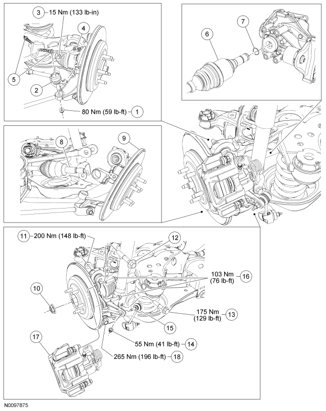
| Item | Part Number | Description |
|---|---|---|
| 1 | W500747 | Toe link-to-wheel knuckle nut |
| 2 | 5B674 | Toe link |
| 3 | W712797 | Wheel speed sensor bolt |
| 4 | 2C190 | Wheel speed sensor |
| 5 | W520214 | Wheel speed sensor harness retainers (part of 2C190) (2 required) |
| 6 | 4K138/139 | Halfshaft inner CV joint |
| 7 | — | Circlip |
| 8 | 4K138/139 | Halfshaft outer CV joint |
| 9 | 5B758/5B759 | Wheel knuckle |
| 10 | W712435 | Wheel hub nut |
| 11 | W520517 | Upper arm-to-wheel knuckle nut |
| 12 | W711479 | Upper arm-to-wheel knuckle bolt |
| 13 | W714033 | Shock absorber lower bolt |
| 14 | W520213 | Stabilizer bar link upper nut |
| 15 | 5D498 LH/ 5C486 RH | Stabilizer bar link |
| 16 | W710681 | Brake caliper anchor plate bolts (2 required) |
| 17 | — | Brake caliper anchor plate and caliper assembly |
| 18 | W711478 | Lower arm-to-wheel knuckle bolt |
Removal
NOTICE: Suspension fasteners are critical parts because they affect performance of vital components and systems and their failure may result in major service expense. New parts must be installed with the same part numbers or equivalent part, if replacement is necessary. Do not use a replacement part of lesser quality or substitute design. Torque values must be used as specified during reassembly to make sure of correct retention of these parts.
NOTICE: Do not allow the caliper to hang from the brake hose or damage to the hose can occur.
Remove and discard the 2 brake caliper anchor plate bolts and position the brake caliper and anchor plate assembly aside.NOTE: Use the hex-holding feature to prevent the stabilizer bar link stud from turning while removing or installing the nut.
Remove and discard the stabilizer bar link upper nut and disconnect the link.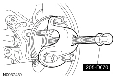
NOTICE: Do not damage the oil seal when removing the axle halfshaft from the differential.
Using a suitable pry bar, remove the halfshaft inner CV joint from the differential.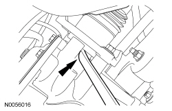
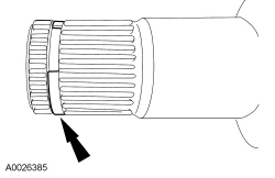
Installation
All vehicles
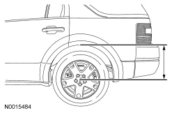
NOTE: Before tightening suspension bushing fasteners, use a jackstand to raise the rear suspension until the distance between the center of the hub and the lip of the fender is equal to the measurement taken in the removal procedure (curb height).
NOTICE: The circlips are unique in size and shape for each shaft. Make sure to use the specified circlip for the application or vehicle damage may occur.
Install a new circlip on the halfshaft.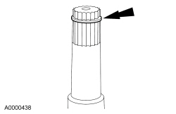
Vehicles equipped with an
RDU
with a stamped steel differential cover
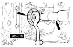
Vehicles equipped with an
RDU
with a aluminum differential cover
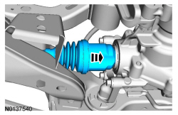
All vehicles
NOTE: A slotted upper arm allows for the rear suspension camber to be adjusted by pushing inward or pulling outward on the wheel knuckle while tightening the upper arm-to-wheel knuckle nut.
With the wheel knuckle pushed inward for maximum negative camber, tighten the upper arm-to-wheel knuckle nut to 200 Nm (148 lb-ft).NOTE: Use the hex-holding feature to prevent the stabilizer bar link stud from turning while removing or installing the nut.
Connect the stabilizer bar link and install a new stabilizer bar link upper nut.NOTICE: Do not tighten the wheel hub nut with the vehicle on the ground. The nut must be tightened to specification before the vehicle is lowered onto the wheels. Wheel bearing damage will occur if the wheel bearing is loaded with the weight of the vehicle applied.
NOTE: Apply the brake to keep the halfshaft from rotating.
Use the previously removed hub nut to seat the halfshaft.NOTICE: The wheel hub nut contains a one-time locking chemical that is activated by the heat created when it is tightened. Install and tighten the new wheel hub nut to specification within 5 minutes of starting it on the threads. Always install a new wheel hub nut after loosening or when not tightened within the specified time or damage to the components can occur.
NOTE: Apply the brake to keep the halfshaft from rotating.
Install a new hub nut.