 WARNING: Before beginning any service procedure in this section, refer to Safety Warnings in
Section 100-00
. Failure to follow this instruction may result in serious personal injury.
SECTION 206-07: Power Brake Actuation
| 2014 Flex Workshop Manual
|
REMOVAL AND INSTALLATION
| Procedure revision date: 05/02/2013
|
Removal
 WARNING: Before beginning any service procedure in this section, refer to Safety Warnings in
Section 100-00
. Failure to follow this instruction may result in serious personal injury.
NOTE: Removal steps in this procedure may contain installation details.
All vehicles
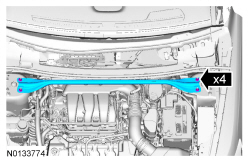
Vehicles equipped with 3.5 L
Ti-VCT
, 3.7L
Ti-VCT
or 2.0L Gasoline Turbocharged Direct Injection (GTDI) engines
Vehicles equipped with 3.5L
GTDI
engine
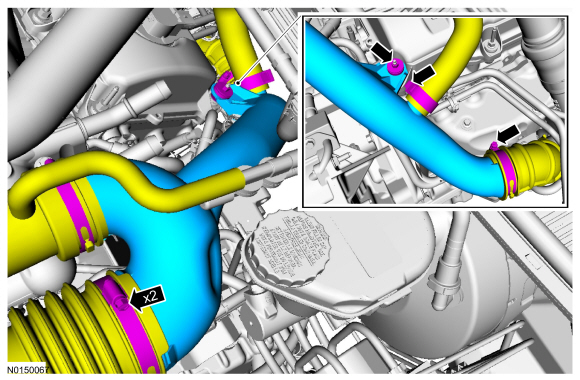
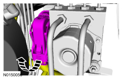
All vehicles
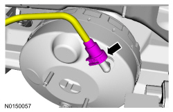
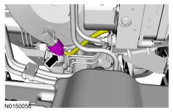
NOTICE: Do not service the brake pedal or brake booster without first removing the stoplamp switch. This switch must be removed with the brake pedal in the at-rest position. The switch plunger must be compressed for the switch to rotate in the bracket. Attempting to remove the switch when the plunger is extended (during pedal apply) will result in damage to the switch.
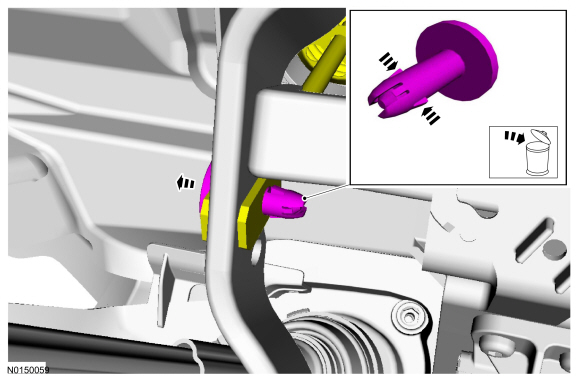
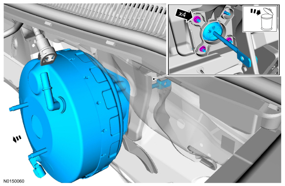
Remove the stoplamp switch. Refer to Section 417-01 .NOTE: The booster push rod clevis-locking pin is a one-time use only part. Any time the booster push rod clevis-locking pin is removed, a new booster push rod clevis-locking pin should be used. Remove the clevis-locking pin by squeezing the locking tabs and pulling outward on the opposite end.
Installation