SECTION 307-01: Automatic Transmission — 6F50/6F55
| 2014 Flex Workshop Manual
|
DISASSEMBLY AND ASSEMBLY
| Procedure revision date: 05/02/2013
|
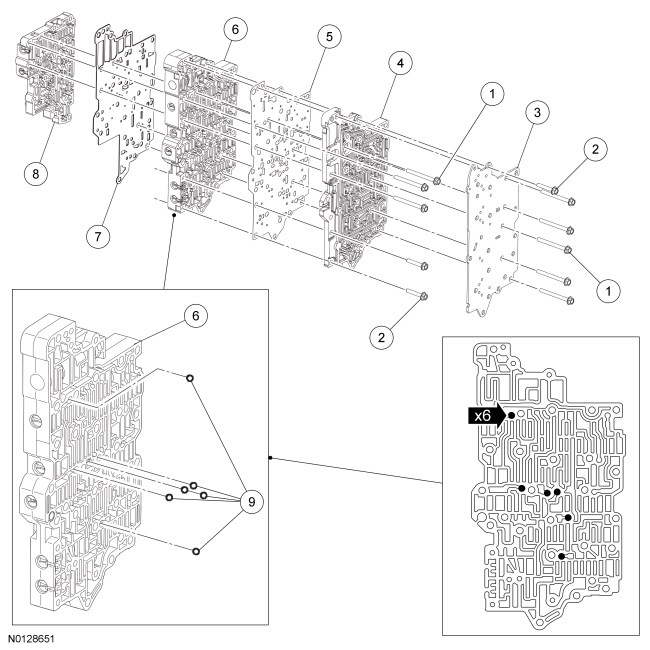
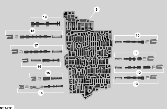
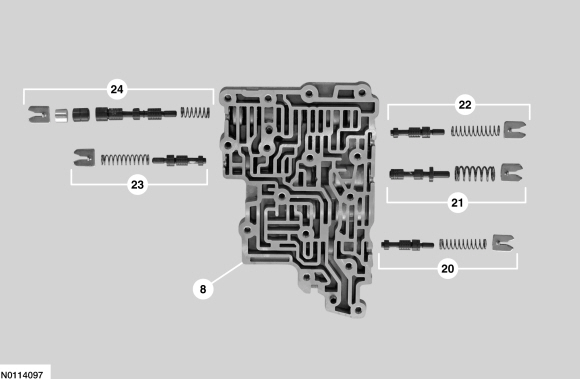
| Item | Description |
|---|---|
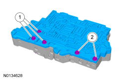
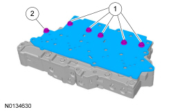
| 1 | Bolts — M6 x 63 |
| 2 | Bolts — M6 x 35 |
| 3 | Cover — transfer plate |
| 4 | Case-to-valve body transfer plate |
| 5 | Separator plate — valve body-to-transfer plate |
| 6 | Main control valve body |
| 7 | Separator plate — main control valve body-to-lower valve body |
| 8 | Lower valve body assembly |
| 9 | Check balls |
| 10 | Low/reverse and overdrive clutch regulator valve assembly |
| 11 | TCC regulator apply valve assembly |
| 12 | Intermediate clutch regulator valve assembly |
| 13 | Direct clutch regulator valve assembly |
| 14 | Pressure regulator valve assembly |
| 15 | Isolator valve assembly |
| 16 | TCC control valve assembly |
| 17 | Multiplex manual valve assembly |
| 18 | Multiplex shift valve assembly |
| 19 | Manual valve |
| 20 | Direct clutch boost valve assembly |
| 21 | Solenoid regulator valve assembly |
| 22 | Low/reverse and overdrive clutch boost valve assembly |
| 23 | Forward clutch boost valve assembly |
| 24 | Forward clutch regulator valve assembly |

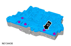
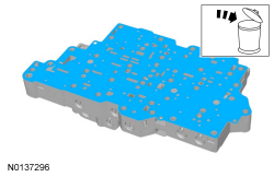
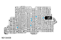
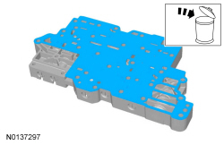
NOTE: Note the location of the check balls for assembly.
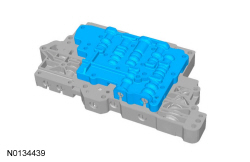
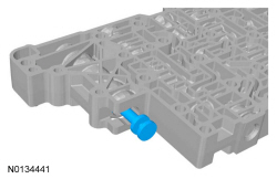
NOTICE: Remove the valves by tapping the valve body on the palm of the hand to slide the valves out of the bores. It may be necessary to remove the valves and springs using a pick. If it is necessary to use a pick, use extreme caution to prevent damaging the valves or valve bores. If necessary, disassemble parts of the main control valve body in small groups. Take special care when handling the main control components, since they are the most precise and delicate parts of the transmission. Neatly arrange the parts as they are removed to avoid mixing similar pieces.
NOTE: Do not stone or polish any valves. If the valves do not move freely, install a new assembly.
Remove the individual valves and springs from the main control valve body and lower valve body by removing the retaining clips. See the Valve Body and Lower Valve Body illustrations at the beginning of this procedure for valve and spring locations. Clean valves, springs, main control valve body and lower valve body.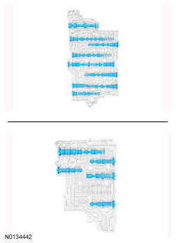
NOTE: Do not stone or polish any valves. If the valves do not move freely during assembly, install a new valve body.
Install the valve body valves, springs and retaining clips in the main control valve body and lower valve body. See the Valve Body and Lower Valve Body illustrations at the beginning of this procedure for valve and spring locations.
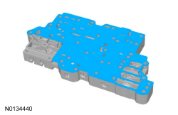

NOTE: Install the check balls in the correct location as noted during disassembly.


