SECTION 309-00: Exhaust System
| 2014 Flex Workshop Manual
|
REMOVAL AND INSTALLATION
| Procedure revision date: 05/02/2013
|
Catalytic Converter — RH Manifold, 3.5L Ti-VCT
Removal
All vehicles
NOTE:
Always install new fasteners and gaskets. Clean flange faces prior to new gasket installation to make sure of correct sealing.
- With the vehicle in NEUTRAL, position it on a hoist. For additional information, refer to
Section 100-02
.
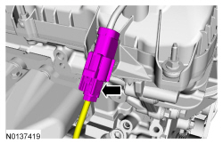
- Disconnect the RH Catalyst Monitor Sensor (CMS) electrical connector.
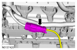
- Disconnect the RH Heated Oxygen Sensor (HO2S) electrical connector.
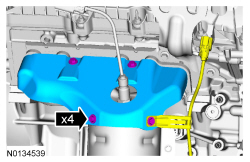
- Remove the 4 bolts and the RH catalytic converter heat shield.
- Remove the exhaust Y-pipe. For additional information, refer to
Exhaust Y-Pipe
in this section.
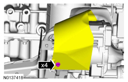
- Remove the 4 bolts and position aside the Electronic Power Assist Steering (EPAS) shield.
All-Wheel Drive (AWD) vehicles
- Remove the transaxle support insulator - anti roll, 3.5L Ti-VCT. For additional information, refer to
Section 307-01
.
All vehicles
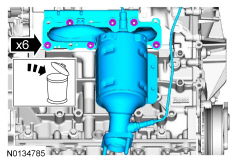
- Remove the 6 nuts and the RH catalytic converter manifold.
- Discard the nuts and RH catalytic converter manifold gasket.
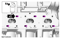
- Remove and discard the 6 RH catalytic converter manifold studs.
Installation
All vehicles
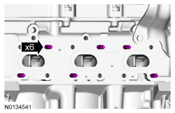
- Install 6 new RH catalytic converter manifold studs.
- Tighten to 12 Nm (106 lb-in).
NOTICE:
Failure to tighten the catalytic converter manifold nuts to specification a second time will cause the exhaust manifold to develop an exhaust leak.
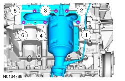
Using a new gasket, install the RH catalytic converter manifold and 6 new nuts. Tighten in 2 stages in the sequence shown:
- Stage 1: Tighten to 20 Nm (177 lb-in).
- Stage 2: Tighten to 25 Nm (18 lb-ft).
All-Wheel Drive (AWD) vehicles
- Install the transaxle support insulator - anti roll, 3.5L Ti-VCT. For additional information, refer to
Section 307-01
.
All vehicles
- Position back the Electronic Power Assist Steering (EPAS) shield and install the 4 bolts
- Tighten to 11 Nm (97 lb-in).
- Install the exhaust Y-pipe. For additional information, refer to
Exhaust Y-Pipe
in this section.
- Install the RH catalytic converter manifold heat shield, Catalyst Monitor Sensor (CMS) wiring harness bracket and the 4 bolts.
- Tighten to 10 Nm (89 lb-in).
- Connect the RH Heated Oxygen Sensor (HO2S) electrical connector.
- Connect the RH Catalyst Monitor Sensor (CMS) electrical connector.
