300-OTC1585AE or equivalent
SECTION 310-01: Fuel Tank and Lines
| 2014 Flex Workshop Manual
|
REMOVAL AND INSTALLATION
| Procedure revision date: 05/02/2013
|
 | Powertrain Lift
300-OTC1585AE or equivalent |
Removal and Installation
 WARNING: Do not smoke, carry lighted tobacco or have an open flame of any type when working on or near any fuel-related component. Highly flammable mixtures are always present and may be ignited. Failure to follow these instructions may result in serious personal injury.
 WARNING: Do not carry personal electronic devices such as cell phones, pagers or audio equipment of any type when working on or near any fuel-related component. Highly flammable mixtures are always present and may be ignited. Failure to follow these instructions may result in serious personal injury.
 WARNING: Before working on or disconnecting any of the fuel tubes or fuel system components, relieve the fuel system pressure to prevent accidental spraying of fuel. Fuel in the fuel system remains under high pressure, even when the engine is not running. Failure to follow this instruction may result in serious personal injury.
 WARNING: When handling fuel, always observe fuel handling precautions and be prepared in the event of fuel spillage. Spilled fuel may be ignited by hot vehicle components or other ignition sources. Failure to follow these instructions may result in serious personal injury.
 WARNING: Always disconnect the battery ground cable at the battery when working on an evaporative emission (EVAP) system or fuel-related component. Highly flammable mixtures are always present and may be ignited. Failure to follow these instructions may result in serious personal injury.
All vehicles
All-Wheel Drive (AWD) vehicles
NOTE: Support the driveshaft.
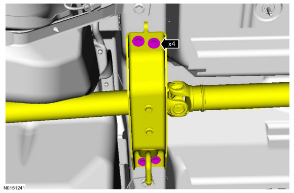
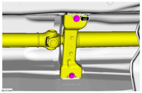
Remove the 4 rear driveshaft center bearing bracket bolts.

NOTICE: Do not reuse the bolt and washer assemblies for the rear Constant Velocity (CV) joint flange. Install new assemblies or damage to the vehicle may occur.
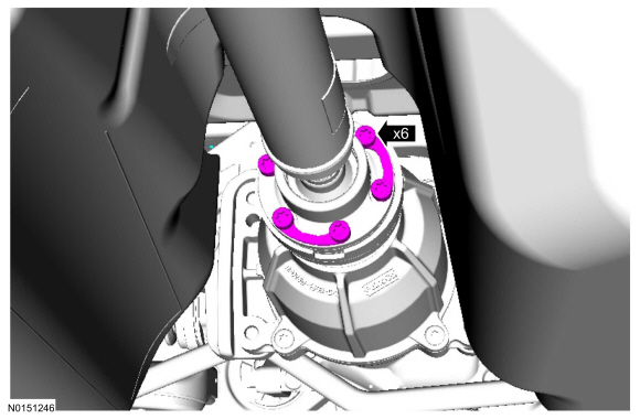
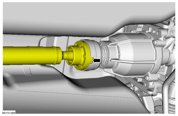
NOTE: Index mark the rear driveshaft flange.
Remove and discard the 3 Rear Drive Unit (RDU) pinion flange bolt and washer assemblies.

All vehicles