SECTION 412-02: Auxiliary Climate Control
| 2014 Flex Workshop Manual
|
REMOVAL AND INSTALLATION
| Procedure revision date: 05/02/2013
|
| Item | Specification |
|---|---|
| Motorcraft® PAG Refrigerant Compressor Oil
YN-12-D | WSH-M1C231-B |

| Item | Part Number | Description |
|---|---|---|
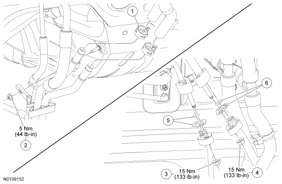
| 1 | 8287 | Front auxiliary heater line heater hose clamp (2 required) |
| 2 | W707137 | Front auxiliary line bracket nut |
| 3 | W520413 | Front auxiliary evaporator inlet line fitting nut |
| 4 | W520413 | Front auxiliary evaporator outlet line fitting nut |
| 5 | 19B596 | O-ring seal and gasket seal kit |
| 6 | 19B596 | O-ring seal and gasket seal kit |

| Item | Part Number | Description |
|---|---|---|
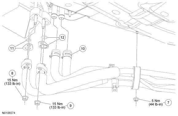
| 7 | W707137 | Rear auxiliary line bracket nut |
| 8 | W520413 | Rear auxiliary evaporator inlet line fitting nut |
| 9 | W520413 | Rear auxiliary evaporator outlet line fitting nut |
| 10 | 8287 | Rear auxiliary heater hose clamp (outlet and inlet) (2 required) |
| 11 | 19B596 | O-ring seal and gasket seal kit |
| 12 | 19B596 | O-ring seal and gasket seal kit |

| Item | Part Number | Description |
|---|---|---|
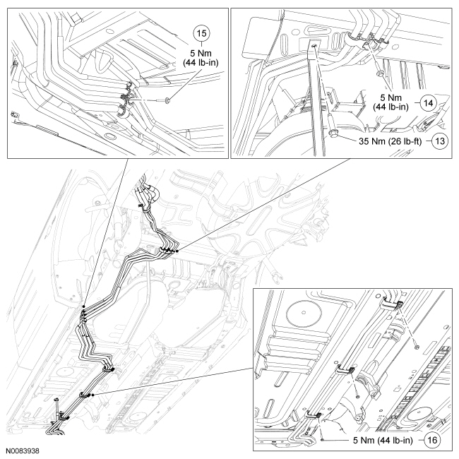
| 13 | N811781 | LH fuel tank strap bolt |
| 14 | W505426 | Rear auxiliary line bracket bolt |
| 15 | W505426 | Rear auxiliary line bracket bolt |
| 16 | W505426 | Middle auxiliary line bracket bolt (3 required) |

| Item | Part Number | Description |
|---|---|---|
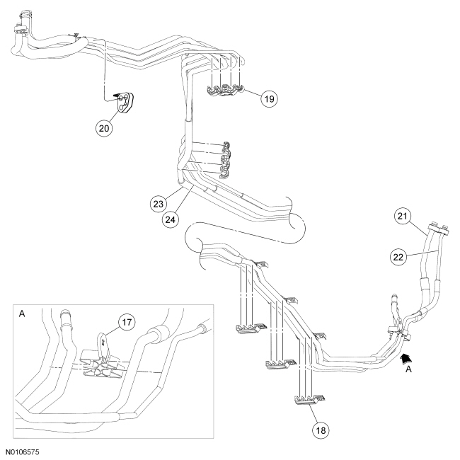
| 17 | 19B632 | Auxiliary line bracket |
| 18 | 19B632 | Auxiliary line bracket (3 required) |
| 19 | 19B632 | Auxiliary line bracket (2 required) |
| 20 | 19B632 | Auxiliary line bracket |
| 21 | 19867 | Auxiliary evaporator outlet line |
| 22 | 19835 | Auxiliary evaporator inlet line |
| 23 | 18663 | Auxiliary heater outlet line |
| 24 | 18696 | Auxiliary heater inlet line |
Removal and Installation
NOTE: Before detaching any of the auxiliary lines from the auxiliary line brackets, mark the position of the line(s) in relation to each bracket to make sure that the line is reinstalled in the correct position.
NOTE: If only one auxiliary evaporator line is to be removed, detach only the desired line from the line brackets whenever possible.
Detach the auxiliary evaporator line(s) from the auxiliary line brackets as needed.