SECTION 413-01: Instrumentation, Message Center, and Warning Chimes
| 2014 Flex Workshop Manual
|
DESCRIPTION AND OPERATION
| Procedure revision date: 05/02/2013
|
Overview
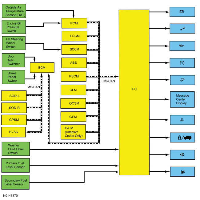
The message center is an integral part of the IPC that receives and acts upon much of the same information that is input and used to operate the IPC gauges, indicators, and warning indicators. The message center uses both hardwired and the network based inputs to receive information.
The message center functionality is controlled through the message center switch (part of the LH steering wheel switch), which is hardwired to the SCCM through input and return circuits.
Whenever conditions are present that require a warning message, the message center replaces the last selected display with the new warning display. Once the message is reset or cleared, the message center returns to the last selected display. If multiple warnings are present, the message center displays each warning for approximately 4 seconds. Warning messages are also generally associated with other observable outputs of the IPC (gauges, indicators and message center indicators). For example, when the BCM detects a low brake fluid condition, the BCM sends the IPC a request to illuminate the brake warning indicator and a request to display the LOW BRAKE FLUID message in the message center. This allows the message center to be a more informative supplement to the IPC gauges and indicators.
Another function of the message center is to display message center warning indicators. Similar to the interaction between the message center and the standard warning indicators, the message center often displays a warning message and the message center warning indicator simultaneously. For example, if the IPC detects low washer fluid level condition, the IPC illuminates the low washer fluid level message center indicator and displays WASHER FLUID LEVEL LOW in the message center. If multiple warnings are present, requiring multiple message center warning indicator displays, the message center cycles or rotates through the displays in the same manner the message center cycles the text messages.
The system warning messages alert the operator to possible problems or malfunctions in the vehicle operating systems. System warning messages may be stand-alone messages but are often associated with another form of indication such as a gauge, an indicator or message center indicator. The message center displays the last selected feature if there are no additional warning messages. Once a warning message has been displayed, the message must be acknowledged to allow full functionality of the message center. Press the OK button to acknowledge and clear the warning message.
When the IPC receives a request to display an informational warning message or a fault condition warning message, the message center may display an informatinal message or a fault condition message. For a complete list of warning messages, refer to the Owner's Literature.
System Operation
Network Message Chart
Module Network Input Messages — IPC
| Broadcast Message | Originating Module | Message Purpose |
|---|---|---|
| Active park assist status | PAM | Inuput used to display the active park assist function messages. |
| Adaptive cruise control/collision avoidance sensor blocked | C-CM | Input used to display the radar sensor blocked warning message for adaptive cruise control and forward collision warning messages. |
| Adaptive cruise control monitor error | BCM | Input used to display the adaptive cruise control system fault message. |
| Adaptive cruise control request denied | C-CM | Input used to control the adaptive cruise control message center indicator and the adaptive cruise control message center message displays. |
| Adaptive cruise control service required | C-CM | Input used to provide the adaptive cruise control system malfunction warning message. |
| Adaptive cruise control message display | C-CM | Used for adaptive cruise control messages. |
| Adaptive headlamp failure message | HCM | Input used to control the check adaptive headlamps message display. |
| AWD lock status | PCM | Input used for the
AWD
message display.
Input used for the AWD control of the powertrain malfunction (wrench) indicator. |
| AWD message display request | PCM | Input used for the AWD message display. |
| Brake fluid level low | BCM | Brake fluid level status for displaying the low brake fluid level warning message. |
| Brake pedal applied | PCM | Input used for the not in park message display. |
| Brake warning indicator request | BCM | Input used for parking brake applied message. |
| Charging system status | PCM | Provides the charging system indication request to control the charging system message center warning indicator and the load shed message display. |
| Collision mitigation by braking monitor error | BCM | Input used to display the forward collision system fault message. |
| Cross traffic information | SOD-L and SOD-R | Input used to provide cross traffic warning messages. |
| Cruise control set speed | PCM | Input used for adaptive cruise control message center indicator and displays. |
| Cruise control status | PCM | Input used for adaptive cruise control message center indicator and message displays. |
| Cruise control override | PCM | Input used for adaptive cruise control message center indicator and message displays. |
| Drivers door ajar status | BCM | Provides the door ajar request to display the driver door ajar message, illuminate the door ajar message center warning indicator and display the not in park message on vehicles with IA . |
| Electronic Power Assist Steering (EPAS) failure | PSCM | Input required for the service power steering message. |
| Engine overheat failsafe mode | PCM | Engine temperature data used for the engine over-temperature message center warning indicator. |
| Engine coolant temperature fault reporting | PCM | Input used to determine the quality of the engine temperature data input for the engine over-temperature message center warning indicator. |
| Engine oil life percent | PCM | Used for the oil life display. |
| Engine rpm | PCM | Input used for the low oil pressure message center warning indicator. |
| Engine service required | PCM | Input used for the ETC component of the powertrain malfunction (wrench) indicator. |
| Forward collision warning system malfunction | C-CM | Input used to display the forward collision system not available message resulting from a system malfunction. |
| Forward collision warning system message display | C-CM | Input used to display the forward collision system warning message. |
| Front camera status | IPM-A | Input used to control the front camera fault message display. |
| Fuel/alcohol percent | PCM | Input used to calulate the DTE display. |
| Fuel fill inlet | PCM | Input required for the display of the fuel fill inlet message. |
| Fuel flow | PCM | Used for average fuel flow, DTE and trip fuel displays. |
| GPS compass direction | GPSM | Provides compass heading data (converted from MS-CAN to HS-CAN in the BCM ) for the compass display (SYNC® only). |
| Ignition status | BCM | Ignition RUN, START and accessory states required for the IPC operating modes and fault reporting. |
| Immobilize indicator | BCM | Input used to provide the starting system fault message for the PATS . |
| Intelligent access system status | BCM | Input used to control the warning messages displayed for IA . |
| Left rear door ajar status | BCM | Provides the door ajar request to display the left rear door ajar message and illuminate the door ajar message center warning indicator. |
| Liftgate/luggage compartment lid ajar status | BCM | Provides the liftgate ajar request to display the liftgate ajar message and illuminate the liftgate ajar message center warning indicator. |
| MyKey® key display | BCM | Input used to provide the MyKey® key information for display messages related to MyKey® key programming and setup. |
| Odometer count | PCM | Rolling count data used for the odometer and trip odometer. |
| OCS object entrapped message request | OCSM | Input used to display the remove objects near the passenger seat warning message. |
| Oil pressure warning | PCM | Provides the oil pressure switch status to control the low oil pressure message center warning indicator. |
| Outside air temperature | BCM | Combined messages for outside air temperature status and outside air temperature data fault reporting for the outside air temperature display. |
| Park brake chime request | BCM | Input used to control the parking brake warning message. |
| Passenger door ajar status | BCM | Provides the door ajar request to display the passenger door ajar message and illuminate the door ajar message center warning indicator. |
| Passenger rear door ajar status | BCM | Provides the door ajar request to display the right rear door ajar message and illuminate the door ajar message center warning indicator. |
| Passive entry/passive start system status | BCM | Input required for the display of the IA messages. |
| Powertrain cooling warning request | PCM | Input used to display the powertrain cooling message display. |
| Stability-traction control warning request | ABS module | Input used to control the service AdvanceTrac® and traction control off warning displays. |
| Steering wheel switch multimedia data (cursor and OK button) | SCCM | Message center switch input from the LH steering wheel switch. |
| Tire pressure status | BCM | Inputs used to provide system fault and low tire warning messages. |
| Trailer sway event in progress | ABS module | Provides trailer sway status request for display of the trailer sway warning message. |
| Transmission display mode actual | PCM | Input used for the not in park message display. |
| Transmission service required | PCM | Input used for the transmission component of the powertrain malfunction (wrench) indicator. |
| Transport mode | BCM | Input used to indicate whether the vehicle is set in factory mode or transport mode to display the appropriate message and power down items such as the PRNDL at key off to conserve the battery. |
| Vehicle speed | PCM | Input used for the not in park message display. |
| Vehicle speed fault reporting | PCM | Input used to determines the quality of the vehicle speed data input for the not in park message display. |
Compass Display
The vehicle heading is displayed in the message center as a 1 or 2 character display that indicates the current direction of the vehicle (N, NE, E, SE, S, SW, W, or NW). The compass signal originates with the GPSM . The GPSM sends the GPS compass direction message to the IPC through (gateway) the BCM to the IPC . No calibration or zone adjustment is available, as the compass heading is based on the GPS signal. Refer to the appropriate section in Group 415 for the procedure.
Keypad Factory Code Display
The message center can display the original keypad factory code when requested. Refer to Section 501-14A or Section 501-14B Description and Operation (D&O) for the procedure to display the keypad factory code.
Oil Change Minder
The message center provides an oil change minder to inform the driver that an oil change is required. The duration of the interval between oil changes is calculated in the PCM and varies due to driving conditions. The PCM assumes a base mileage of 16,090 km (10,000 mi) or 1 year for normal driving. However, this number is adjusted down for conditions such as high engine temperature, high engine Revolutions Per Minute (RPM), use of flex fuel and possibly low oil level. The PCM calculates and provides an engine oil life percent message to the IPC .
When the remaining oil life is between 1%-5%, the message center displays the change oil soon message. When the remaing oil life is at 0%, the message center displays the oil change required message.
Outside Air Temperature Display
The AAT sensor is hardwired to the PCM through separate input and return circuits. The PCM provides a reference voltage to the AAT sensor and monitors the change in voltage resulting from changes in resistance as determined by outside air temperature. The PCM messages the outside air temperature data to the HVAC module through the BCM . The HVAC module filters the temperature data and sends the updated temperature status back to the BCM . The BCM in turn messages the outside air temperature in degrees Celsius (metric) to the IPC . When the Fahrenheit (English) display is selected by the driver, the IPC converts the Celsius to Fahrenheit and displays the temperature in the message center.
The HVAC module is programmed to update the messaged outside temperature data at different rates depending on several criteria to prevent false temperature displays due to a condition known as heat soaking. Heat soaking is where the air temperature in the location of the AAT sensor is hotter than the actual outside air temperature.
When the sensed outside temperature rises, the display updates slowly at varying rates based on vehicle speed. When the sensed outside temperature drops, the display updates more quickly following the drop experienced by the AAT sensor.
Cruise Control Message Center Indicator
The IPC receives the cruise control status message from the PCM. When the cruise control switch is placed in the ON position, the PCM sends the IPC a standby mode request through the cruise control status message and the IPC illuminates the cruise control indicator in gray. When the cruise control is engaged, the PCM sends a cruise control on request through the cruise control status message to the IPC and the IPC changes the cruise control indicator illumination from gray to green.
Charging System Message Center Indicator
The charging system message center warning indicator is controlled by the IPC based upon data received from the BCM . The BCM receives the charging system status from the PCM. When a fault is detected in the charging system, the BCM sends the IPC a charging system status message to illuminate the charging system message center warning indicator. Refer to Section 414-00 .
Door/Liftgate Ajar Message Center Indicator
The IPC receives the door ajar status for the LF, RF, LR, and liftgate ajar switches from the BCM . When the IPC receives a driver door, passenger door, left rear door, right rear door or liftgate ajar status message from the BCM that one or more doors or the liftgate are open or ajar, the IPC illuminates the appropriate door/liftgate ajar message center warning indicator.
Engine Over-Temperature Message Center Warning Indicator
The PCM uses the CHT sensor to measure the engine temperature. The IPC receives the engine coolant temperature data message from the PCM. The IPC requires 2 basic messaged inputs to control the engine over-temperature message center warning indicator. The first is the engine overheat failsafe mode message. The second is an engine coolant temperature fault reporting message. When the engine temperature reaches 121°C (250°F) and when the PCM sends the engine overheat failsafe mode message and does not receive the engine coolant temperature fault reporting message, the IPC illuminates the engine over-temperature message center warning indicator.
Grade Assist Message Center Indicator
The IPC receives the grade assist on/off status from the PCM. When the grade assist function is selected off, the PCM sends the transmission shift mode message to the IPC to illuminate the grade assist message center indicator.
Low Fuel Message Center Indicator
The IPC uses the average fuel level to determine when to turn on the low fuel message center indicator. On single sender L-shaped fuel tank configurations, the IPC uses the input from the fuel pump assembly. On dual sender saddle-type fuel tank configurations, the IPC uses an average of the combined fuel level inputs.
When an administrator key is in use, the low fuel message center indicator turns on when the fuel level is approximately 1/8 tank. When a MyKey® programmed key is in use, the low fuel message center indicator is turned on when the fuel level is approximately 3/16 tank.
Low Oil Pressure Message Center Warning Indicator
The engine oil pressure switch is hardwired to the PCM. The PCM provides the oil pressure warning message and engine rpm message to the IPC over the HS-CAN communication bus. The IPC requires engine rpm above 500 rpm before the message center displays the low oil pressure message center indicator.
The PCM provides a reference voltage to the engine oil pressure switch when the ignition is in RUN. With the engine running and low or no oil pressure, the engine oil pressure switch remains open. The PCM detects no change in the reference voltage and provides the IPC a request to illuminate the low oil pressure warning indicator. With the engine running and sufficient oil pressure, the engine oil pressure switch closes, pulling the reference voltage low. The PCM detects the low reference voltage and provides the IPC the oil pressure warning message to turn off the low oil pressure warning indicator.
The engine oil pressure switch is hardwired to the PCM. The IPC receives the oil pressure warning message and the engine rpm message from the PCM. With the KOEO , the IPC does not display the low oil pressure message center warning indicator until the engine is started and it receives the engine rpm message.
Low Washer Fluid Message Center Indicator
The low washer fluid level switch is hardwired to the IPC through a single signal circuit and is grounded through a separate ground circuit. The IPC provides a reference voltage to the washer fluid level switch. When the washer fluid is low, the washer fluid level switch closes to ground, pulling the reference voltage low. When the IPC detects the washer fluid input pulled low and illuminates the low washer fluid level message center warning indicator.
Powertrain Malfunction (Wrench) Message Center Indicator
The IPC receives the ETC , AWD and the transmission status from the PCM.
When a fault condition exists in the ETC system, the PCM provides the IPC with the engine service required message to illuminate the powertrain malfunction (wrench) message center warning indicator.
When a fault condition exists in the transmission, the PCM provides the IPC with the transmission service required message to illuminate the powertrain malfunction (wrench) message center warning indicator.
When a fault condition exists in the AWD system, the PCM provides the IPC with the AWD lock status message to illuminate the powertrain malfunction (wrench) message center warning indicator.
Adaptive Cruise Control Display
The IPC receives the adaptive cruise control display message request from the C-CM .
When a fault exists in the adaptive cruise control system or for a specific system status, the C-CM sends the IPC a message to display the appropriate message. When the driver has selected a specific speed or gap setting, the C-CM sends the IPC a message to display the driver selected setting. Refer to Section 419-03B
TPMS Message Display
The IPC receives the tire pressure status message from the BCM . When the tires are in training mode, a fault condition exists or a low tire pressure condition exists, the IPC displays a TPMS message to indicate the system status.
Check Fuel Fill Message Display
The PCM monitors the fuel tank evaporative emission system for significant leaks that occur following refueling of the vehicle. Once the PCM detects a fuel vapor leak, the PCM sends a fuel fill inlet message to the IPC to display the CHECK FUEL FILL INLET message. The PCM only sets a fault code following a successful cruise test, which is initiated when the vehicle is driven at a steady speed above 64 km/h (40 mph) for a duration of approximately 4-5 minutes. If the PCM is unable to successfully run the cruise test, the IPC does not receive the fuel fill inlet message and the CHECK FUEL FILL INLET message remains off.
Engine Idle Shut Down Message Display (Push Button Start)
The message center provides messages to indicate the status of the engine idle shut down. If there is no driver interaction with the vehicle for 30 minutes with the engine idling, the message center displays a warning that the engine is about to be shut down. The driver then can override the shut down for the current ignition cycle through the message center if desired. The IPC provides the engine idle system disable message and receives the engine idle shut down system status from the BCM .
Service AdvanceTrac® Message Display
The IPC receives the stability-traction control warning request from the ABS module. When a fault exists in the stabilty-traction control system, the ABS module sends the stability-traction control warning request to the IPC to display the service advancetrac message and sound the service advancetrac warning chime.
Shift To Park Message Display
The IPC uses inputs from the PCM and BCM to control the shift to park message display. The inputs from the PCM are the transmission display mode actual, the brake pedal applied, the vehicle speed and the vehicle speed fault reporting. The messages from the BCM are the driver's door ajar status and igntion status.
When the selector lever is out of the PARK (P) position with the vehicle stopped (no vehicle speed input) and the brake pedal not applied, the ignition is off and the driver door is ajar, the IPC displays the shift to park message in the message center.
Component Description
Steering Wheel Switch - Message Center
The message center switch portion of the LH steering wheel switch is comprised of 5 buttons. Each button operates a unique switch within the message center switch portion of the LH steering wheel switch assembly. Each button uses a different resistance value. The SCCM sends out a reference voltage to the LH steering wheel switch on the input circuit and monitors the voltage drop when a message center switch button is pressed. The voltage drop varies depending upon the resistance of the specific button pressed, indicating to the SCCM which switch is pressed.
Low Washer Fluid Level Switch
The low washer fluid level switch is a reed type switch. The low washer fluid switch is hardwired to the IPC through a single signal wire and is grounded to a body ground through a separate circuit. The IPC provides a reference voltage to the low washer fluid level switch. When the washer fluid level is low, the float drops closing the switch and pulling the reference voltage low. When the washer fluid level is high, the float lifts off the switch and opens the circuit to the IPC sending the reference voltage high.