SECTION 413-06: Horn
| 2014 Flex Workshop Manual
|
DESCRIPTION AND OPERATION
| Procedure revision date: 05/02/2013
|
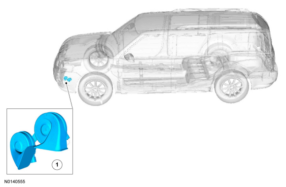
Component Location

| Item | Description | Comments |
|---|---|---|
| 1 | Horn | Located behind LH front fender splash shield |
Overview
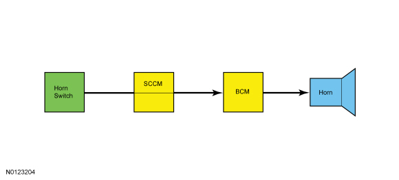
The horn emits an audible tone when the driver air bag module is pressed. The horn output is controlled by a relay, which is integral to the BCM .
System Operation

Horn Operation
The horn switch consists of 2 sets of contacts separated by springs. The lower set is connected to ground and the upper set is connected to the horn signal circuit.
When the driver air bag module is pressed, it pushes down on the upper set of contacts, collapsing the springs and allowing the contacts to touch. When the contacts touch, it completes the circuit and provides the ground signal which is routed through the clockspring, the SCCM and then to the horn relay, which is integral to the BCM .
The BCM supplies the control and switched (load) voltage to the horn relay. When energized, the horn relay provides voltage to the horn, enabling the horn to sound.