SECTION 414-01: Battery, Mounting and Cables
| 2014 Flex Workshop Manual
|
REMOVAL AND INSTALLATION
| Procedure revision date: 05/02/2013
|
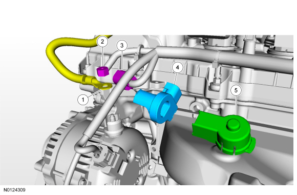
NOTE: 3.5L GTDI shown, 3.5L Ti-VCT similar.

| Item | Part Number | Description |
|---|---|---|
| 1 | — | Generator B+ terminal (part of 14B060) |
| 2 | 14B357 | Generator B+ terminal nut - 17 Nm (150 lb-in) |
| 3 | — | Generator current sensor electrical connector (part of 14B060) |
| 4 | — | Generator current sensor |
| 5 | — | Generator B+ terminal cover (part of 14B060) |
Removal
NOTE: Note the orientation and position of the generator current sensor tape tab.
Index-mark the battery cable at the generator current sensor. Remove and discard the tape securing the generator current sensor to the battery cable and remove the generator current sensor.Installation
NOTE: The generator current sensor must be installed in the proper position and orientation to function correctly.
With the generator current sensor tape tab pointing upward, position the generator current sensor to the index-mark on the battery cable and secure with electrical tape.