SECTION 419-10: Multifunction Electronic Modules
| 2014 Flex Workshop Manual
|
DESCRIPTION AND OPERATION
| Procedure revision date: 05/02/2013
|
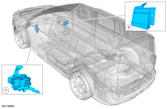
Component Location

| Item | Description | Comments |
|---|---|---|
| 1 | BCM | - |
| 2 | RFA module | - |
Overview
The BCM controls the following:
The RFA module (with IA ) controls the following:
System Operation
Battery Saver
NOTE: The battery saver time-out is 1 minute if the vehicle has less than 201 km (125 mi).
NOTE: The battery saver does not control the parking lamps if the headlamp switch is in the PARKING LAMPS ON position.
To save battery voltage, the BCM provides automatic shut-off of the interior and exterior lamps after a time-out period when the ignition is off. The BCM monitors the ignition state and input from the RKE system to determine when to energize or de-energize the battery saver relay and to shut the power off to the lamps.
A timer in the BCM starts when:
When 10 minutes have elapsed, the BCM automatically shuts off voltage to the lamps. The timer restarts (voltage is restored if the BCM is in battery saver mode) if:
Post Crash Alert Function
The post crash alert is a function controlled by the BCM . If the Restraints Control Module (RCM) determines an impact of enough severity (the air bags may or may not be deployed), the post crash alert function activates. The post crash alert function activates the hazard lamp function and cycles the horn on 3 times, then off for 4 seconds, and repeats this cycle until the battery is discharged or the function is turned off.
The post crash alert function can be turned off by:
FET Protection
A FET is a type of transistor that, when used with module software, monitors and controls current flow on module outputs. The FET protection strategy prevents module damage in the event of excessive current flow.
The BCM utilizes a FET protective circuit strategy for many of its outputs (for example, a headlamp output circuit). Output loads (current level) are monitored for excessive current (typically short circuits) and are shut down (turns off the voltage or ground provided by the module) when a fault event is detected. A short circuit DTC is stored at the fault event and a cumulative counter is started.
When the demand for the output is no longer present, the module resets the FET circuit protection to allow the circuit to function. The next time the driver requests a circuit to activate that has been shut down by a previous short ( FET protection) and the circuit is still shorted, the FET protection shuts off the circuit again and the cumulative counter advances.
When the excessive circuit load occurs often enough, the module shuts down the output until a repair procedure is carried out. Each FET protected circuit has 3 predefined levels of short circuit tolerance based on the harmful effect of each circuit fault on the FET and the ability of the FET to withstand it. A module lifetime level of fault events is established based upon the durability of the FET . If the total tolerance level is determined to be 600 fault events, the 3 predefined levels would be 200, 400 and 600 fault events.
When each tolerance level is reached, DTC U1000:00 should set along with the short circuit DTC that was stored on the first failure. These DTCs cannot be cleared until the vehicle is repaired.
After the repair, it is necessary to clear the DTCs using the Clear DTC operation on the scan tool, cycling the ignition, and run the BCM on-demand self-test.
The module never resets the fault event counter to zero and continues to advance the fault event counter as short circuit fault events occur. If the number of short circuit fault events reach the third level, DTC U3000:49 sets along with the associated short circuit DTC. DTC U3000:49 cannot be cleared and the module must be replaced after the initial fault is repaired.
Gateway Function
The BCM acts as a gateway module by receiving information in one format and transmitting it to other modules using another format. For example, when the BCM receives the vehicle speed data from the PCM over the HS-CAN , the BCM converts the data into a MS-CAN message and sends (gateways) the message to other network modules such as the HVAC module. This enables network communication between modules that do not communicate using the same network ( HS-CAN or MS-CAN ).
Component Description
Body Control Module (BCM)
The BCM is a multifunction module that requires a PMI when replaced. Refer to Section 418-01 .
Remote Function Actuator (RFA) Module
The RFA module is a multifunction module that requires a PMI when replaced. Refer to Section 418-01 .