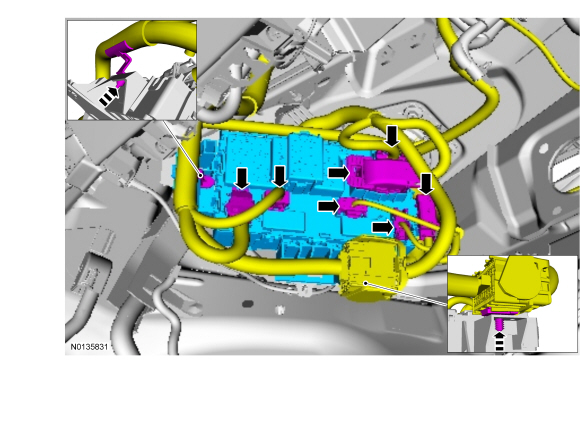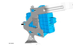
SECTION 419-10: Multifunction Electronic Modules
| 2014 Flex Workshop Manual
|
REMOVAL AND INSTALLATION
| Procedure revision date: 05/02/2013
|
Removal
NOTICE: When any vehicle module is being programmed, connect an external battery charger to make sure that the module programming is completed without the interruption due to the load shedding feature becoming active. The external battery charger must maintain a system voltage above 13 volts. This can require a charger setting higher than the lowest charge setting. The external battery charger negative connection must be made to an engine or vehicle chassis ground and not the negative battery terminal. If the connection is to the negative battery terminal, load shedding cannot be prevented from being invoked and module programming may be corrupted. After charging has begun, start the engine to clear any load shed states and then turn the engine off and proceed with programming.
NOTE: If installing a new module, it is necessary to upload the module configuration information to the scan tool prior to removing the module. This information must be downloaded into the new module after installation.
NOTE: If installing a new BCM , all vehicle keys are erased during the parameter reset procedure. For vehicles without Intelligent Access (IA) verify at least 2 of the vehicle keys are available prior to carrying out this procedure.
NOTE: This step is necessary only if the BCM is being replaced.
Upload the module configuration information from the BCM . Refer to Section 418-01 .

Installation
NOTE: If the BCM was not replaced, this is the last step that is necessary.
Install the steering column opening trim panel.NOTE: If the ignition is left in RUN or ACC and the engine is OFF during the vehicle battery charging process, the Battery Monitoring System (BMS) can turn off the ignition causing the configuration to fail.
After battery charging is complete, carry out the BMS reset by following the scan tool on screen instructions.NOTE: Once the BCM Programmable Module Installation (PMI) is complete, follow the scan tool on-screen instructions for performing the Configurable Engine Immobilizer (CEI) lock configuration.
Download the BCM configuration information from the scan tool to the new BCM by following the scan tool on screen instructions.NOTE: If a new BCM is installed, the BCM and the PCM require a parameter reset to allow the BCM and PCM to recognize each other.
If installing a new BCM , carry out the parameter reset procedure and program the keys. For vehicles without Intelligent Access (IA), refer to Section 419-01B . For vehicles with IA , refer to Section 419-01C .NOTE: If the dome lamps are flashing after BCM installation, it was not configured completely. Repeat steps 3 through 7.
Carry out the BCM self-test to confirm all DTCs have been cleared.