SECTION 501-12: Instrument Panel and Console
2014 Flex Workshop Manual
REMOVAL AND INSTALLATION
Procedure revision date: 05/02/2013

Instrument Panel Upper Section

Removal and Installation

All vehicles
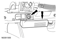
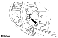
  1. Position the steering wheel downward.
  1. Remove the front floor console. Refer to Console — Front, Floor .
  1. Remove the LH and RH A-pillar trim panels. Refer to Section 501-05 .
  1. Remove the LH and RH instrument panel side trim panels.
  1. Remove the steering wheel. Refer to Section 211-04 .
  1. Remove the instrument cluster finish panel. Refer to Instrument Cluster Finish Panel .
  1. Remove the 4 Instrument Panel Cluster (IPC) screws.
  1. Remove the IPC .
  1. Remove the 2 multifunction switch screws.
  1. Remove the multifunction switch.
  1. Disconnect the headlamp switch electrical connector through the instrument cluster finish panel opening.
  1. Remove the hood release handle screw and position the handle aside.

Vehicles with 4.2-inch (107 mm) screen
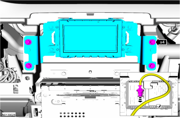
  1. Remove the 4 Front Control/Display Interface Module (FCDIM) screws and remove the FCDIM .
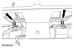
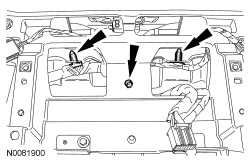
  1. Detach the 2 wire harness pin-type retainers located in the FCDIM opening.
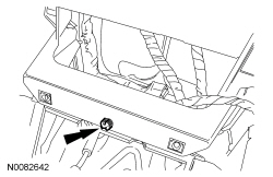
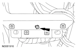
  1. Detach the wire harness pin-type retainer located below the FCDIM .
  1. Remove the 4 Audio Control Module (ACM) screws and remove the ACM .

Vehicles with 8-inch (203 mm) touchscreen
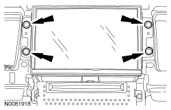
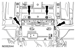
  1. Remove the 4 FDIM screws.
  1. Remove the FDIM .
  1. Detach the 3 wire harness pin-type retainers located in the FDIM opening.
  1. Detach the wire harness pin-type retainer located below the FCIM .
  1. Remove the 4 Audio Control Module (ACM) screws and remove the ACM .

All vehicles

  1. Remove the light sensor from the instrument panel upper section.
  1. If equipped, remove the instrument panel speaker. Refer to Section 415-00B or Section 415-00C .
  1. Remove the LH and RH front door scuff plate trim panels.
  1. Remove the LH and RH lower cowl trim panels.
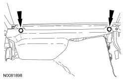
  1. Remove the 2 RH lower instrument panel insulator pushpin retainers.
  1. Remove the RH lower instrument panel insulator.
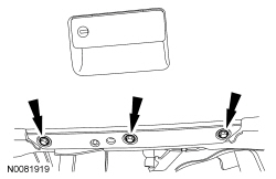
  1. Remove the 3 glove compartment screws.
  1. Remove the glove compartment assembly.
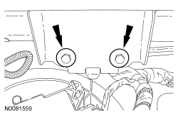
  1. Remove the 2 passenger air bag-to-cross beam bolts.
  1. Remove the 13 instrument panel upper section screws.
  1. Slightly pull the RH side of the instrument panel upper section outward to gain access to the passenger side air bag connectors.
  1. Disconnect the 2 passenger air bag connectors.
  1. Depress the retainers and remove the HVAC module from the instrument panel upper section.
  1. If equipped, position aside theGlobal Positioning System Module (GPSM) antenna bracket from the instrument panel.
  1. NOTICE: To avoid damaging the upper section, the aid of an assistant is required to carry out this step.

    NOTICE: Make sure that all electrical connectors and wiring are not hindered before removing the upper section or damage to the components may occur.

    Remove the instrument panel upper section.
  1. NOTICE: To avoid damaging the instrument panel, the aid of an assistant is required when positioning the upper section to the vehicle.

    NOTICE: Make sure that all electrical connectors and wiring are correctly routed when installing the upper section or damage to the components may occur.

    To install, reverse the removal procedure.