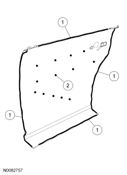
SECTION 501-35: Body Repairs
| 2014 Flex Workshop Manual
|
REMOVAL AND INSTALLATION
| Procedure revision date: 05/02/2013
|
Door Outer Panel
General Equipment
| 3 Phase Inverter Spot Welder 254-00002
|
| I4 Inverter Spot Welder 254-00014
|
Material
| Item
| Specification
|
|---|
Motorcraft® Metal Bonding Adhesive
TA-1
| —
|
Door Assembly
NOTE:
Front door shown, rear door similar. The front door panel(s) contains a reinforcement brace that is part of the outer panel and is not serviceable. The rear door(s) is designed without this reinforcement.
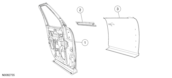
| Item
| Part Number
| Description
| | 1
| 20125 LH/ 20124 RH
| Door assembly
|
| 2
| 21124
| Upper belt reinforcement
|
| 3
| 20201 LH/ 20200 RH
| Door outer panel
|
 WARNING: Collision damage repair must conform to the instructions contained in this workshop manual. Replacement components must be new, genuine Ford Motor Company parts. Recycled, salvaged, aftermarket or reconditioned parts (including body parts, wheels or safety restraint components) are not authorized by Ford.
Departure from the instructions provided in this manual, including alternate repair methods or the use of substitute components, risks compromising crash safety. Failure to follow these instructions may adversely affect structural integrity and crash safety performance, which could result in serious personal injury to vehicle occupants in a crash.
 WARNING: Invisible ultraviolet and infrared rays emitted in welding can injure unprotected eyes and skin. Always use protection such as a welder's helmet with dark-colored filter lenses of the correct density. Electric welding will produce intense radiation, therefore, filter plate lenses of the deepest shade providing adequate visibility are recommended. It is strongly recommended that persons working in the weld area wear flash safety goggles. Also wear protective clothing. Failure to follow these instructions may result in serious personal injury.
 WARNING: Always wear protective equipment including eye protection with side shields, and a dust mask when sanding or grinding. Failure to follow these instructions may result in serious personal injury.
NOTE:
The door is manufactured with an open lower hem flange to allow for proper application of heat cured adhesive at the plant. The flange is closed when serviced in the field, using standard repair methods.
- Remove the door trim panel from the affected door. For additional information, refer to
Section 501-05
.
- Remove the outside door handle and mirror assembly. For additional information, refer to
Section 501-09
.
NOTE:
Window applique will break when removed. A new applique is required after removal.
Remove door trim including mouldings and weatherstrips.
- Remove the door assembly and secure on a workstand.
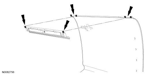
- Using a spot weld cutter, drill out the spot welds at the corners of the outer panel and panel reinforcement.
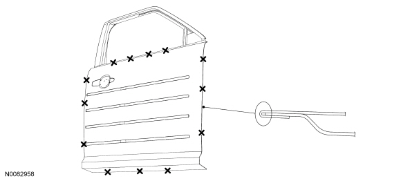
- Using a grinder, grind along the perimeter of the door hem to separate the hem edges.
NOTE:
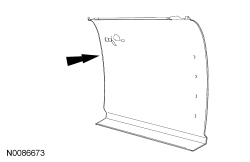
Make note of mastic sound deadener material location when removing the original panel. Replacement of this material in the original location is required to maintain the NVH performance of the door assembly.
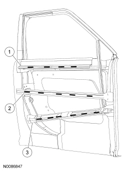
Prior to removing the outer panel, use a sharp knife to cut the adhesive between the door outer panel, flutter beam, beltline reinforcement and intrusion beam.
- Remove the mastic sound deadening material between the door reinforcements and the outer panel.
- Using a flat-blade chisel or equivalent, remove the original panel.
NOTE:
The use of a heat gun may be necessary to aid in removal of the remaining door hem flange.
Using a suitable tool, remove the remaining hem flange material from the inner portion of the door shell.
Installation
- Trial fit the service replacement panel to the door shell assembly.
- Prepare the service replacement panel joint areas by grinding clean all mating surfaces.
- Prepare the door shell assembly by grinding clean all the mating surfaces including the inner hem, outer belt reinforcement to outer panel, intrusion and flutter beams.
- Outer belt reinforcement
- Flutter beam
- Intrusion beam
- Prepare the service replacement panel for installation, lightly scuff sanding all mating surfaces to aid adhesion.
- Apply metal bonding adhesive to the service replacement panel hem flange.
- Apply a locally obtained flexible foam sound deadener material to the new panel at the upper beltline, flutter beam and intrusion beam.
- Position and align the new door skin to the door shell assembly, carefully turn the assembly over and begin the hemming process.
- Using a door panel installation tool or the hammer and dolly method, close the perimeter door hem and smooth any residual adhesive in the joints.
- Turn the door over and weld the upper corners of the door, using Squeeze-Type Resistance Spot Welding (STRW) method. Finish grind and trial fit the upper beltline moulding and mirror.
- Prime and paint the door using Ford-approved paint system.
- Apply rust inhibitor to all hem areas and upper beltline area. For additional information, refer to
Restoring Corrosion Protection Following Repair
in this section.
- Reassemble, install the door and align. For additional information regarding door fitment specifications, refer to
Body
in this section.
 WARNING: Collision damage repair must conform to the instructions contained in this workshop manual. Replacement components must be new, genuine Ford Motor Company parts. Recycled, salvaged, aftermarket or reconditioned parts (including body parts, wheels or safety restraint components) are not authorized by Ford.

