NUD105-R025D or equivalent

SGT27000
SECTION 303-06: Starting System
| 2014 Flex Workshop Manual
|
DIAGNOSIS AND TESTING
| Procedure revision date: 06/28/2013
|
 | Flex Probe Kit
NUD105-R025D or equivalent |
 | Circuit Tester / Test Light
SGT27000 |
Inspection and Verification
Diagnostics in this manual assume a certain skill level and knowledge of Ford-specific diagnostic practices. Refer to Section 100-00 for information regarding Ford-specific diagnostic practices.
DTC Charts
Diagnostics in this manual assume a certain skill level and knowledge of Ford-specific diagnostic practices. Refer to Diagnostic Methods in Section 100-00 for information about these practices.
RFA DTC Chart
NOTE: Any push-button start system fault results in DTCs being stored in the RFA module and BCM . Correct all RFA module DTCs prior to diagnosing the BCM DTCs .
| DTC | Description | Action |
|---|---|---|
| RFA DTCs | For all RFA DTCs | REFER to Section 419-10 . |
PCM DTC Chart
| DTC | Description | Action |
|---|---|---|
| PCM DTCs | PCM DTCs not listed in this chart | REFER to Section 303-14 . |
| P0512 | Starter Request Circuit | CARRY OUT the Ignition Switch component test. Refer to Wiring Diagrams Cell 149 for component testing. If necessary, INSTALL a new ignition switch. REFER to Section 211-05 . If the ignition switch passed the component test, REPAIR circuit CDC35 (BU/WH) for a short to voltage. |
| P0706 | Transmission Range Sensor "A" Circuit Range/Performance | REFER to Section 307-01 . |
| P0708 | Transmission Range Sensor "A" Circuit High | REFER to Section 307-01 . |
| P161A | Incorrect Response From Immobilizer Control Module | REFER to Section 419-01B or Section 419-01C . |
| P1702 | Transmission Range Sensor Circuit Intermittent | REFER to Section 307-01 . |
| P1705 | Transmission Range Circuit Not Indicating Park/Neutral During Self Test | REFER to Section 307-01 . |
BCM DTC Chart
| DTC | Description | Action |
|---|---|---|
| BCM DTCs | BCM DTCs not listed in this chart | REFER to Section 419-10 . |
| B1305:01 | Hood Switch: General Electrical Failure | REFER to Section 419-01A . |
| C113A:11 | Wake up Control: Circuit Short to Ground | GO to Pinpoint Test D . |
| C113A:15 | Wake up Control: Circuit Short to Battery or Open | GO to Pinpoint Test D . |
| U1000:00 | Solid State Driver Protection Activated - Driver Disabled: No Sub Type Information | The BCM has temporarily disabled an output because an excessive current draw exists (such as a short to ground). The BCM cannot enable the output until the cause of the short is corrected. ADDRESS all other DTCs first. After the cause of the concern is corrected, CLEAR the DTCs . REPEAT the self-test. |
TPM DTC Chart
| DTC | Description | Action |
|---|---|---|
| TPM DTCs | TPM DTCs not listed in this chart | REFER to Section 419-10 . |
| B1D55:01 | Antenna #2: General Electrical Failure | GO to Pinpoint Test E . |
Symptom Chart
Diagnostics in this manual assume a certain skill level and knowledge of Ford-specific diagnostic practices. Refer to Diagnostic Methods in Section 100-00 for information about these practices.
| Condition | Possible Sources | Action |
|---|---|---|
|
| |
|
| |
|
|
|
|
|
|
|
| |
|
|
|
|
| |
|
|
|
|
| |
|
|
Pinpoint Tests
Pinpoint Test A: The Engine Does Not Crank (Without Push Button Start)
Diagnostics in this manual assume a certain skill level and knowledge of Ford-specific diagnostic practices. Refer to Diagnostic Methods in Section 100-00 for information about these practices.
Refer to Wiring Diagrams Cell 20 , Starting System for schematic and connector information.
The BCM and PCM receive a request to crank the engine when the ignition switch is turned to the START position. When the PCM receives the correct inputs from the BCM , voltage from the Run/start relay, and notification from the TR sensor that the gear selector is in PARK or NEUTRAL, the PCM then supplies voltage and ground to the starter relay coil. The energized coil causes the starter relay contacts to close. This allows voltage to be supplied from the BJB to the starter solenoid coil. The starter solenoid coil is grounded at the starter motor. Energizing the starter solenoid closes the solenoid contacts allowing voltage directly from the battery to the starter motor, engaging the starter drive into the ring gear causing the engine to crank. The PCM disengages the starter motor once an engine Revolutions Per Minute (RPM) threshold is reached, a set crank time is exceeded or the ignition switch has been turned to the OFF position.
| Test Step | Result / Action to Take | ||||||||||||||||||
|---|---|---|---|---|---|---|---|---|---|---|---|---|---|---|---|---|---|---|---|
| A1 PERFORM INSPECTION AND VERIFICATION | |||||||||||||||||||
NOTE: Make sure battery voltage is greater than 12.2 volts prior to and during this pinpoint test. NOTE: If it is necessary to leave the battery charger connected during testing, do not leave it on its highest or boost setting. The highest settings can exceed 16 volts, resulting in false test results and setting of DTCs . | Yes
Correct the cause as necessary. No GO to A2 | ||||||||||||||||||
| A2 CHECK FOR ANY MESSAGES IN THE MESSAGE CENTER | |||||||||||||||||||
| Yes
DIAGNOSE STARTING SYSTEM FAULT displayed in the message center. REFER to Section 419-01B , Symptom Chart: Passive Anti-Theft System (PATS). No GO to A3 . | ||||||||||||||||||
| A3 VERIFY THE BCM AND PCM PASS THE NETWORK TEST | |||||||||||||||||||
| Yes
GO to A4 . No Refer to Section 418-00 . | ||||||||||||||||||
| A4 RETRIEVE BCM AND PCM DTCs | |||||||||||||||||||
| Yes
REFER to DTC Charts in this section. No GO to A5 . | ||||||||||||||||||
| A5 CHECK BCM IGN_SW_STATE PID | |||||||||||||||||||
| Yes
GO to A6 No DIAGNOSE No power in Start. REFER to Section 211-05 . | ||||||||||||||||||
| A6 CHECK THE IN GEAR-TRANSMISSION IS APPLYING A LOAD TO ENGINE (IN_GEAR) PID . | |||||||||||||||||||
| Yes
GO to A7 . No Diagnose the TR Sensor. REFER to Section 307-01 . | ||||||||||||||||||
| A7 CHECK THE ENGINE CRANKING (ENG_CRANK) PID | |||||||||||||||||||
| Yes
GO to A10 . No GO to A8 . | ||||||||||||||||||
| A8 CHECK THE START CIRCUIT FOR VOLTAGE AT THE PCM | |||||||||||||||||||
| Yes
GO to A20 . No GO to A9 . | ||||||||||||||||||
| A9 CHECK THE IGNITION SWITCH | |||||||||||||||||||
| Yes
REPAIR circuit CDC35 (BU/WH) for an open. No INSTALL a new ignition switch. REFER to Section 211-05 . | ||||||||||||||||||
| A10 CHECK THE STARTER RELAY CONTROL OPERATION | |||||||||||||||||||
| Yes
GO to A11 . No GO to A18 . | ||||||||||||||||||
| A11 CHECK THE VOLTAGE TO THE STARTER RELAY | |||||||||||||||||||
| Yes
GO to A12 . No VERIFY BJB fuse 19 (30A) is OK. If OK, REPAIR the circuit for an open. If not OK, REFER to the Wiring Diagrams manual to identify the possible causes of the circuit short. | ||||||||||||||||||
| A12 CHECK THE STARTER MOTOR OPERATION AT THE STARTER RELAY | |||||||||||||||||||
| Yes
INSTALL a new starter relay. No GO to A13 . | ||||||||||||||||||
| A13 CHECK THE BATTERY GROUND CABLE | |||||||||||||||||||
| Yes
GO to A14 . No INSTALL new battery cables. REFER to Section 414-01 . | ||||||||||||||||||
| A14 CHECK THE STARTER MOTOR GROUND | |||||||||||||||||||
| Yes
GO to A15 . No CLEAN the starter motor mounting flange and MAKE SURE the starter motor is correctly mounted. | ||||||||||||||||||
| A15 CHECK THE VOLTAGE TO THE STARTER MOTOR | |||||||||||||||||||
| Yes
GO to A16 . No INSTALL new battery cables. REFER to Section 414-01 . | ||||||||||||||||||
| A16 CHECK THE STARTER MOTOR FOR CORRECT OPERATION | |||||||||||||||||||
| Yes
GO to A17 . No INSTALL a new starter motor. REFER to Starter Motor — 3.5L GTDI or Starter Motor — 3.5L Ti-VCT . | ||||||||||||||||||
| A17 CHECK FOR START INPUT AT THE STARTER | |||||||||||||||||||
| Yes
CLEAN the starter solenoid (S-Terminal) and C197B. CHECK the wiring and the starter motor for a loose or intermittent connection. No REPAIR the circuit for an open. | ||||||||||||||||||
| A18 CHECK THE PCM START CIRCUITS FOR A SHORT TO GROUND | |||||||||||||||||||
| Yes
GO to A19 . No REPAIR the affected circuit for a short to ground. | ||||||||||||||||||
| A19 CHECK THE PCM START CIRCUITS FOR AN OPEN | |||||||||||||||||||
| Yes
GO to A20 . No REPAIR the affected circuit for an open. | ||||||||||||||||||
| A20 CHECK FOR CORRECT PCM OPERATION | |||||||||||||||||||
| Yes
CHECK OASIS for any applicable TSBs . If a TSB exists for this concern, DISCONTINUE this test and FOLLOW the TSB instructions. If no TSB address this concern, INSTALL a new PCM . REFER to Section 303-14 . No The system is operating correctly at this time. The concern may have been caused by module connections. ADDRESS the root cause of any connector or pin issues. |
Pinpoint Test B: The Engine Does Not Crank — With Push Button Start
Diagnostics in this manual assume a certain skill level and knowledge of Ford-specific diagnostic practices. Refer to Diagnostic Methods in Section 100-00 for information about these practices.
Refer to Wiring Diagrams Cell 20 , Starting System for schematic and connector information.
Refer to Wiring Diagrams Cell 90 , Turn Signal/ Stop/ Hazard Lamps for schematic and connector information.
When the Start/stop switch is pressed in combination with the brake pedal, the RFA , BCM and PCM receive signals requesting to crank and start the engine. The PCM and RFA module receive notification from the TR sensor that the gear selector is in PARK or NEUTRAL. The PCM requires a voltage signal from the Run/start relay to operate. The PCM then supplies voltage and ground to the starter relay coil. The energized coil causes the starter relay contacts to close which allows voltage to be supplied from the BJB to the starter solenoid coil. The starter solenoid coil is grounded at the starter motor. Energizing the starter solenoid closes the solenoid contacts allowing voltage directly from the battery to the starter motor, engaging the starter drive into the ring gear causing the engine to crank. The PCM disengages the starter motor once an engine Revolutions Per Minute (RPM) threshold is reached, a set crank time is exceeded or the Start/stop switch is pressed indicating an engine shutdown request.
| Test Step | Result / Action to Take | ||||||||||||||||||
|---|---|---|---|---|---|---|---|---|---|---|---|---|---|---|---|---|---|---|---|
| B1 PERFORM INSPECTION AND VERIFICATION | |||||||||||||||||||
NOTE: Make sure battery voltage is greater than 12.2 volts prior to and during this pinpoint test. NOTE: If it is necessary to leave the battery charger connected during testing, do not leave it on its highest or boost setting. The highest settings can exceed 16 volts, resulting in false test results and setting of DTCs . | Yes
Correct the cause as necessary. No GO to B2 . | ||||||||||||||||||
| B2 CHECK FOR NO KEY DETECTED MESSAGE IN THE MESSAGE CENTER | |||||||||||||||||||
| Yes
DIAGNOSE NO KEY DETECTED is displayed in the message center REFER to Section 419-01C . No GO to B3 . | ||||||||||||||||||
| B3 CHECK THE IPC OPERATION | |||||||||||||||||||
| Yes
GO to B5 . No GO to B4 . | ||||||||||||||||||
| B4 CHECK FOR COMMUNICATION WITH THE SCAN TOOL | |||||||||||||||||||
| Yes
DIAGNOSE No Power in Run. REFER to Section 211-05 . No DIAGNOSE the module not responding to scan tool. REFER to Section 418-00 . | ||||||||||||||||||
| B5 RETRIEVE DTCs | |||||||||||||||||||
| Yes
REFER to DTC Charts in this section. No GO to B6 . | ||||||||||||||||||
| B6 CHECK THE CRANK FACTOR BRAKE (Crk_Fact_Brk) PID | |||||||||||||||||||
| Yes
GO to B9 . No GO to B7 . | ||||||||||||||||||
| B7 CHECK THE OPERATION OF THE STOPLAMPS | |||||||||||||||||||
| Yes
GO to B8 . No DIAGNOSE All The Stoplamps Are Inoperative. REFER to Section 417-01 . | ||||||||||||||||||
| B8 CHECK THE BPP SWITCH CIRCUIT FOR VOLTAGE AT THE RFA MODULE | |||||||||||||||||||
| Yes
GO to B23 . No REPAIR the circuit for an open. | ||||||||||||||||||
| B9 CHECK THE IN GEAR-TRANSMISSION IS APPLYING A LOAD TO ENGINE (IN_GEAR) PID | |||||||||||||||||||
| Yes
GO to B10 . No DIAGNOSE the TR Sensor. REFER to Section 307-01 . | ||||||||||||||||||
| B10 CHECK THE ENGINE CRANKING (ENG_CRANK) PID | |||||||||||||||||||
| Yes
GO to B11 . No GO to B21 . | ||||||||||||||||||
| B11 CHECK THE STARTER RELAY CONTROL OPERATION | |||||||||||||||||||
| Yes
GO to B12 . No GO to B19 . | ||||||||||||||||||
| B12 CHECK THE VOLTAGE TO THE STARTER RELAY | |||||||||||||||||||
| Yes
GO to B13 . No VERIFY BJB fuse 19 (30A) is OK. If OK, REPAIR the circuit for an open. If not OK, REFER to the Wiring Diagrams manual to identify the possible causes of the circuit short. | ||||||||||||||||||
| B13 CHECK THE STARTER MOTOR OPERATION AT THE STARTER RELAY | |||||||||||||||||||
| Yes
INSTALL a new starter relay. No GO to B14 . | ||||||||||||||||||
| B14 CHECK THE BATTERY GROUND CABLE | |||||||||||||||||||
| Yes
GO to B15 . No INSTALL new battery cables. REFER to Section 414-01 . | ||||||||||||||||||
| B15 CHECK THE STARTER MOTOR GROUND | |||||||||||||||||||
| Yes
GO to B16 . No CLEAN the starter motor mounting flange and MAKE SURE the starter motor is correctly mounted. | ||||||||||||||||||
| B16 CHECK THE VOLTAGE TO THE STARTER MOTOR | |||||||||||||||||||
| Yes
GO to B17 . No INSTALL new battery cables. REFER to Section 414-01 . | ||||||||||||||||||
| B17 CHECK THE STARTER MOTOR FOR CORRECT OPERATION | |||||||||||||||||||
| Yes
GO to B18 . No INSTALL a new starter motor. REFER to Starter Motor — 3.5L GTDI or Starter Motor — 3.5L Ti-VCT . | ||||||||||||||||||
| B18 CHECK FOR START INPUT AT THE STARTER | |||||||||||||||||||
| Yes
CLEAN the starter solenoid (S-Terminal) and C197B. CHECK the wiring and the starter motor for a loose or intermittent connection. No REPAIR the circuit for an open. | ||||||||||||||||||
| B19 CHECK THE PCM START CIRCUITS FOR A SHORT TO GROUND | |||||||||||||||||||
| Yes
GO to B20 . No REPAIR the affected circuit for a short to ground. | ||||||||||||||||||
| B20 CHECK THE PCM START CIRCUITS FOR AN OPEN | |||||||||||||||||||
| Yes
GO to B24 . No REPAIR the affected circuit for an open. | ||||||||||||||||||
| B21 CHECK THE START CIRCUIT FOR VOLTAGE AT THE PCM | |||||||||||||||||||
| Yes
GO to B24 . No GO to B22 . | ||||||||||||||||||
| B22 CHECK THE ENGINE START STOP BUTTON CIRCUIT 1 (START_STOP_1) PID | |||||||||||||||||||
| Yes
REPAIR the circuit for an open. No DIAGNOSE the Start/stop switch. REFER to Section 211-05 . | ||||||||||||||||||
| B23 CHECK FOR CORRECT RFA MODULE OPERATION | |||||||||||||||||||
| Yes
CHECK OASIS for any applicable TSBs . If a TSB exists for this concern, DISCONTINUE this test and FOLLOW the TSB instructions. If no TSBs address this concern, INSTALL a new RFA module. REFER to Section 419-10 . No The system is operating correctly at this time. The concern may have been caused by module connections. ADDRESS the root cause of any connector or pin issues. | ||||||||||||||||||
| B24 CHECK FOR CORRECT PCM OPERATION | |||||||||||||||||||
| Yes
CHECK OASIS for any applicable TSBs . If a TSB exists for this concern, DISCONTINUE this test and FOLLOW the TSB instructions. If no TSB address this concern, INSTALL a new PCM . REFER to Section 303-14 . No The system is operating correctly at this time. The concern may have been caused by module connections. ADDRESS the root cause of any connector or pin issues. |
Pinpoint Test C: Unusual Starter Noise
Diagnostics in this manual assume a certain skill level and knowledge of Ford-specific diagnostic practices. Refer to Diagnostic Methods in Section 100-00 for information about these practices.
| Test Step | Result / Action to Take |
|---|---|
| C1 CHECK THE STARTER MOUNTING | |
| Yes
GO to C2 . No Tighten the starter bolts to specifications, REFER to Starter Motor — 3.5L GTDI or Starter Motor — 3.5L Ti-VCT . Test system for normal operation, if noise is still present GO to C2 . |
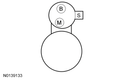
| C2 CHECK FOR ENGINE NOISE | |
 | Yes
GO to C3 . No REFER to Section 303-00 to continue diagnosis. |
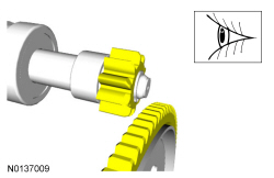
| C3 STARTER MOTOR DRIVE GEAR AND RING GEAR INSPECTION | |
 | Yes
Replace the starter. REFER to Starter Motor — 3.5L GTDI or Starter Motor — 3.5L Ti-VCT . No If the starter drive gear and the flexplate ring gear are not fully meshing or the gears are milled or damaged, install a new flexplate and a new starter motor. REFER to Section 303-01A or Section 303-01B and Starter Motor — 3.5L GTDI or Starter Motor — 3.5L Ti-VCT . |
Pinpoint Test D: DTC C113A:11 OR C113A:15
Diagnostics in this manual assume a certain skill level and knowledge of Ford-specific diagnostic practices. Refer to Diagnostic Methods in Section 100-00 for information about these practices.
Refer to Wiring Diagrams Cell 112 , Passive Anti-Theft System for schematic and connector information.
The wake up control circuit is used to wake up the PCM prior to engine cranking. The PCM needs to wake up prior to a crank request so that it has time to go through its own initialization. The wake up control circuit also powers the Passive Anti-Theft System (PATS) transceiver (if equipped). The wake up control circuit is controlled by the Body Control Module (BCM) and receives voltage from fuse 18 (10A).
The BCM activates the wake up control circuit when:
DTC Fault Trigger Conditions
| DTC | Description | Fault Trigger Conditions |
|---|---|---|
| Wake up Control: Circuit Short To Ground | Sets when the BCM detects a short to ground on the wake up control circuit. |
| Wake up Control: Circuit Short To Battery or Open | Sets when the BCM detects a short to voltage or an open on the wake up control circuit. |
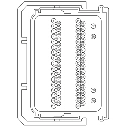
NOTICE: Use the correct probe adapter(s) when making measurements. Failure to use the correct probe adapter(s) may damage the connector.
| Test Step | Result / Action to Take | ||||||||||||||||||||||||||||||||||||
|---|---|---|---|---|---|---|---|---|---|---|---|---|---|---|---|---|---|---|---|---|---|---|---|---|---|---|---|---|---|---|---|---|---|---|---|---|---|
| D1 RETRIEVE THE BCM DTCs | |||||||||||||||||||||||||||||||||||||
| Yes
GO to D2 . No GO to D5 . | ||||||||||||||||||||||||||||||||||||
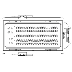
| D2 CHECK THE WAKE UP CONTROL CIRCUIT FOR A SHORT TO VOLTAGE | |||||||||||||||||||||||||||||||||||||
 | Yes
REPAIR the circuit. No GO to D3 . | ||||||||||||||||||||||||||||||||||||
| D3 CHECK THE WAKE UP CONTROL CIRCUIT FOR AN OPEN | |||||||||||||||||||||||||||||||||||||


 | Yes
GO to D4 . No REPAIR the circuit for an open. | ||||||||||||||||||||||||||||||||||||
| D4 CHECK THE BCM AND PCM FOR CORRECT OPERATION | |||||||||||||||||||||||||||||||||||||


 | Yes
GO to D8 . No VERIFY BCM fuse 18 (10A) is OK. If OK, GO to D9 . If not OK, REFER to the Wiring Diagrams manual to identify the possible causes of the circuit short. | ||||||||||||||||||||||||||||||||||||
| D5 CHECK THE WAKE UP CONTROL CIRCUIT DTCs FOR A FAULT STATUS CHANGE (SHORT TO GROUND INDICATED) | |||||||||||||||||||||||||||||||||||||
| Yes
GO to D6 . No GO to D7 . | ||||||||||||||||||||||||||||||||||||
| D6 CHECK THE WAKE UP CONTROL CIRCUIT FOR A SHORT TO GROUND | |||||||||||||||||||||||||||||||||||||

 | Yes
GO to D9 . No REPAIR the circuit. | ||||||||||||||||||||||||||||||||||||
| D7 CHECK THE BCM FOR DTCs | |||||||||||||||||||||||||||||||||||||
| Yes
GO to D8 . No For vehicles without Push button start, INSTALL a new PATS transceiver. REFER to Section 419-01A . For vehicles with Push button start, the system is operating correctly at this time. The concern may have been caused by loose or corroded connector. ADDRESS the root cause of any connector or pin issues. | ||||||||||||||||||||||||||||||||||||
| D8 CHECK FOR CORRECT PCM OPERATION | |||||||||||||||||||||||||||||||||||||
| Yes
CHECK OASIS for any applicable TSBs . If a TSB exists for this concern, DISCONTINUE this test and FOLLOW the TSB instructions. If no TSB addresses this concern, INSTALL a new PCM . Section 303-14 No The system is operating correctly at this time. The concern may have been caused by a loose or corroded connector. ADDRESS the root cause of any connector or pin issues. | ||||||||||||||||||||||||||||||||||||
| D9 CHECK FOR CORRECT BCM OPERATION | |||||||||||||||||||||||||||||||||||||
| Yes
CHECK OASIS for any applicable TSBs . If a TSB exists for this concern, DISCONTINUE this test and FOLLOW the TSB instructions. If no TSB addresses this concern, INSTALL a new BCM . REFER to Section 419-10 . No The system is operating correctly at this time. The concern may have been caused by a loose or corroded connector. ADDRESS the root cause of any connector or pin issues. |
Pinpoint Test E: DTC B1D55:01
Diagnostics in this manual assume a certain skill level and knowledge of Ford-specific diagnostic practices. Refer to Diagnostic Methods in Section 100-00 for information about these practices.
An external antenna connected to the Tire Pressure Monitor Module (TPM) receives a signal from the Integrated Keyhead Transmitter (IKT) or Intelligent Access (IA) key to enable activation of the remote start function from a distance of up to 100 meters (328 feet). If the external antenna fails, the remote start operates with a reduction in the range of operation.
DTC Fault Trigger Conditions
| DTC | Description | Fault Trigger Conditions |
|---|---|---|
| Antenna #2: General Electrical Failure | Sets if the vehicle is equipped with remote start but the system feedback circuit does not detect an external antenna. |
| Test Step | Result / Action to Take |
|---|---|
| E1 CHECK THE EXTERNAL ANTENNA CONNECTION | |
| Yes
REPAIR as necessary. No GO to E2 . |
| E2 CHECK THE EXTERNAL ANTENNA | |
| Yes
Fault is corrected. No GO to E3 . |
| E3 CHECK THE EXTERNAL ANTENNA CABLE | |
| Yes
Fault is corrected. No INSTALL a new TPM . REFER to Section 204-04 . |
Pinpoint test F: The Remote Start Is Inoperative
Diagnostics in this manual assume a certain skill level and knowledge of Ford-specific diagnostic practices. Refer to Diagnostic Methods in Section 100-00 for information about these practices.
The factory equipped remote start system enables the engine to be started from up to 100 meters (328 feet) away by pressing a sequence of buttons on the IKT or IA key. To activate the remote start system, press the lock button once to make sure the doors are locked, followed by 2 presses of the remote start button. The 3 button presses must occur within 3 seconds of each other. The IKT or IA key signal is received through an external antenna attached to the Tire Pressure Monitor Module (TPM) and communicated over the Medium Speed Controller Area Network (MS-CAN) to initiate the vehicle start.
| Test Step | Result / Action to Take | ||||||||||||||||||||||||
|---|---|---|---|---|---|---|---|---|---|---|---|---|---|---|---|---|---|---|---|---|---|---|---|---|---|
| F1 CHECK THE OPERATION OF THE IKT OR IA KEY | |||||||||||||||||||||||||
| Yes
GO to F2 . No REFER to Section 501-14A to diagnose and repair the Remote Keyless Entry (RKE) system. Diagnose and repair the Remote Keyless Entry (RKE) system. REFER to Section 501-14A (without IA ) or REFER to Section 501-14B (with IA ). | ||||||||||||||||||||||||
| F2 CHECK THE ENGINE FOR CRANKING | |||||||||||||||||||||||||
| Yes
GO to F3 . No This not a remote start issue. To diagnose the no crank condition for vehicles without IA , GO to Pinpoint Test A . To diagnose the no crank condition for vehicles with IA , GO to Pinpoint Test B . | ||||||||||||||||||||||||
| F3 CHECK FOR ILLUMINATED ENGINE WARNING LAMPS | |||||||||||||||||||||||||
| Yes
CARRY OUT self-test of the PCM . DIAGNOSE and REPAIR any DTCs present. REFER to PCM DTC Chart Section 303-14 . No GO to F4 . | ||||||||||||||||||||||||
| F4 RETRIEVE BCM AND TPM DTCs | |||||||||||||||||||||||||
| Yes
REFER to the BCM DTC Chart or TPM DTC Chart in this section. No GO to F5 . | ||||||||||||||||||||||||
| F5 CONFIRM THE REMOTE START FUNCTION IS ENABLED | |||||||||||||||||||||||||
| Yes
GO to F6 . No ENABLE the remote start function. | ||||||||||||||||||||||||
| F6 CHECK THE BCM LAST RECEIVED RKE TRANSMITTER BUTTON PRESS (LST_RKE_xMTR) or RFA MODULE LAST RECEIVED TRANSMITTER ID BUTTON PRESS (LST_XM_B_PRS) TRANSMITTER PID | |||||||||||||||||||||||||
| Yes
GO to F7 . No REPLACE and PROGRAM new IKT or IA key. REFER to Section 419-01A . | ||||||||||||||||||||||||
| F7 CHECK THE PCM WAKE UP CIRCUIT | |||||||||||||||||||||||||

 | Yes
GO to F8 . No VERIFY BCM fuse 18 (10A) is OK. If OK, REPAIR circuit CE436 (VT/OG) for an open. If not OK, REFER to the Wiring Diagrams manual to identify the possible causes of the circuit short. | ||||||||||||||||||||||||
| F8 CHECK THE REMOTE START PRECONDITIONS FOR CORRECT OPERATION | |||||||||||||||||||||||||
NOTE: The Body Control Module (BCM) acknowledges the remote start request and that all preconditions have been met by providing 2 short flashes of the exterior lights. | Yes
GO to F9 . No CARRY OUT the required precondition as necessary. | ||||||||||||||||||||||||
| F9 CHECK FOR CORRECT PCM OPERATION | |||||||||||||||||||||||||
| Yes
CHECK OASIS for any applicable TSBs . If a TSB exists for this concern, DISCONTINUE this test and FOLLOW the TSB instructions. If no TSB addresses this concern, INSTALL a new PCM . REFER to Section 303-14 . CLEAR all DTCs in all modules. No The system is operating correctly at this time. The concern may have been caused by a loose or corroded connector. ADDRESS the root cause of any connector or pin issues. |
Component Tests
 WARNING: Before beginning any service procedure in this section, refer to Safety Warnings in
Section 100-00
. Failure to follow this instruction may result in serious personal injury.
 WARNING: Always disconnect the battery ground cable at the battery before disconnecting the starter motor battery terminal lead. If a tool is shorted at the starter motor battery terminal, the tool can quickly heat enough to cause a skin burn. Failure to follow this instruction may result in serious personal injury.
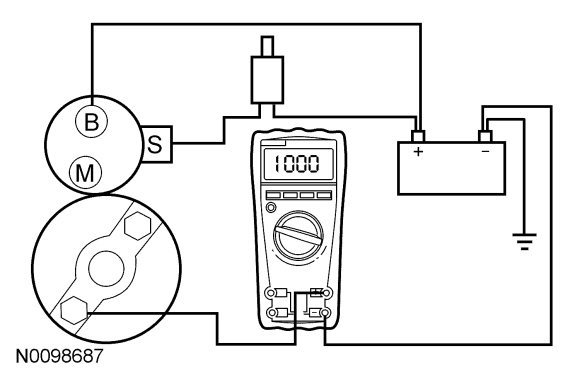
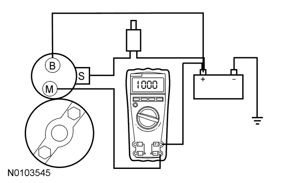
Always make the Fluke 77-IV Digital Multimeter connections at the component terminal rather than at the wiring end connector. Making a connection at the wiring end connector could result in false readings because the meter will not pick up a high resistance between the wiring connector and the component.
Starter Motor — Feed Circuit Test
Starter Motor - Ground Circuit Test
 WARNING: Before beginning any service procedure in this section, refer to Safety Warnings in
Section 100-00
. Failure to follow this instruction may result in serious personal injury.
A slow cranking condition can be caused by resistance in the ground or return portion of the cranking circuit. Check the voltage drop in the ground circuit as follows:
