SECTION 307-01: Automatic Transmission — 6F50/6F55
| 2014 Flex Workshop Manual
|
REMOVAL AND INSTALLATION
| Procedure revision date: 05/02/2013
|
Transaxle — 3.5L GTDI
Special Tool(s)
 | Adapter, Transmission Jack
209-00152
|
 | Bar, Engine Spreader
303-1454
|
 | Disconnect Tool, Transmission Cooler Line
307-569
|
 | Eye, Engine Lift
303-1245
|
 | Retainer, Torque Converter
307-346
|
 | Support Bar, Engine
303-F072
|
Material
| Item
| Specification
|
|---|
Motorcraft® MERCON® LV Automatic Transmission Fluid
XT-10-QLVC (US); CXT-10-LV12 (Canada)
| MERCON® LV
|
Motorcraft® Multi-Purpose Grease
XL-5
| ESB-M1C93-B
|
Removal
NOTE:
Refer to the Transmission Cooler Flushing Job Aid on the FMCDealer website.
- With the vehicle in NEUTRAL, position it on a hoist. Refer to
Section 100-02
.
- Remove the battery and battery tray. Refer to
Section 414-01
.
- Remove the
outlet pipe. Refer to
Section 303-12
.
- Remove the cowl panel grille. Refer to
Section 501-02
.
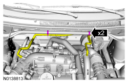
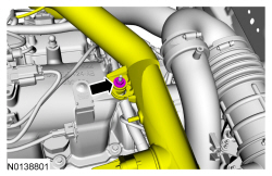
- Remove the crankcase vent tube. Refer to
Section 310-00
.
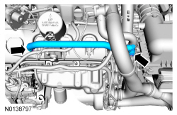
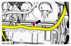
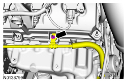
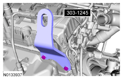
- Special Tool(s): Eye, Engine Lift 303-1245.
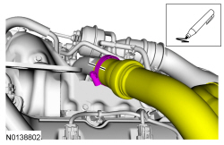
NOTE:
Index-mark the
tube position for reference during installation.
Marker.
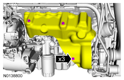
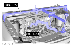
- Special Tool(s): Support Bar, Engine 303-F072, Bar, Engine Spreader 303-1454.
- Remove the front subframe. Refer to
Section 502-00
.
- Remove the roll restrictors. Refer to
Transaxle Support Insulator — Anti-Roll, 3.5L GTDI
.
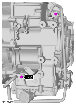
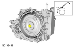
- Drain the transmission fluid.
- Tighten to 9 Nm (80 lb-in).
- Remove the LH front halfshaft. Refer to
Section 205-04
.
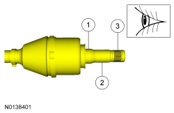
- Visual check.
- Inspect the differential seal surface.
- Inspect the halfshaft bushing surface. If this surface is damaged, inspect the halfshaft bushing for damage.
- Inspect the differential side gear splines.
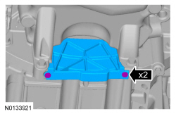
- Remove the
. Refer to
Section 308-07B
.
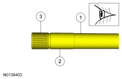
- Visual check.
- Inspect the differential seal surface.
- Inspect the halfshaft bushing surface. If this surface is damaged, inspect the halfshaft bushing for damage.
- Inspect the differential side gear splines.
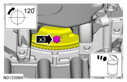
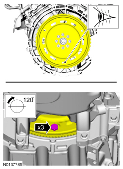
- Turn the component
through 120 degrees 3 times. Discard the specified component. Follow local disposal regulations.
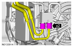
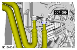
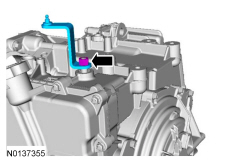
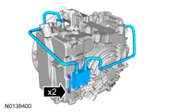
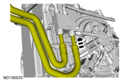
- Special Tool(s): Disconnect Tool, Transmission Cooler Line 307-569.
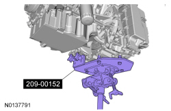
- Special Tool(s): Adapter, Transmission Jack 209-00152.
General equipment: Transmission jack.
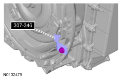
- Special Tool(s): Retainer, Torque Converter 307-346
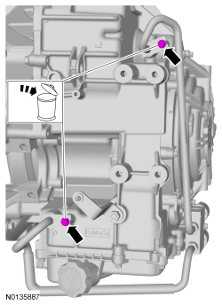
- Discard the specified component. Follow local disposal regulations.
NOTE:
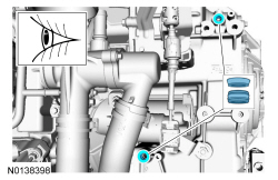
If the transmission fluid cooler tube seals or backing rings are stuck in the transmission case, remove the seals and backing rings.
Visual check.
- If the transmission is to be overhauled or if installing a new or re-manufactured transmission, carry out transmission fluid cooler backflushing and cleaning. Refer to
Section 307-02
.
Installation
NOTICE:
Prior to installation of a new, re-manufactured or overhauled transmission, the transmission fluid cooler tubes must be cleaned, otherwise transmission failure may occur.
NOTE:
Prior to installation of a new, re-manufactured or overhauled transmission, flush out the cooler and cooler tubes. Refer to
Section 307-02
.
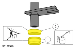
- Visual check. Apply the specified lubricant to the specified component.
- Seal
- Backing ring
- Tighten to 9 Nm (80 lb-in).
- Tighten to 9 Nm (80 lb-in).
NOTICE:
Make sure that when installing the manual control lever, it is fully seated onto the manual control lever shaft. Damage to the manual control lever shaft will occur and the manual lever will come loose.
NOTICE:
Make sure to hold the manual control lever while tightening the manual control lever nut or damage to the manual control lever and park components will occur.
- Tighten to 18 Nm (159 lb-in).
- Apply the specified lubricant to the specified component.
Material: Multi-Purpose Grease XG-4 and/or XL-5
NOTICE:
If the transmission is not positioned on the dowel pins, damage to the transmission may occur.
NOTE:
If the dowel pins were pulled out of the engine block during removal, install new dowel pins in the engine block.
Visual check.
- Special Tool(s): Retainer, Torque Converter 307-346
- Install the transmission on the engine dowels.
Special Tool(s): Adapter, Transmission Jack 209-00152.
General equipment: Transmission jack.
- Tighten to 48 Nm (35 lb-ft).
NOTICE:
Use only the specified bolts for the torque converter. Standard length fasteners may bottom out and damage the torque converter clutch apply surface.
Turn the component
through 120 degrees 3 times.
Install 3 new torque converter bolts (W714722).
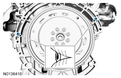
- Install the first torque converter bolt in the slotted hole on the flexplate.
- Tighten to 55 Nm (41 lb-ft).
- Install the
. Refer to
Section 308-07B
.
- Install the LH halfshaft. Refer to
Section 205-00
.
- Install the front subframe. Refer to
Section 502-00
.
- Install the roll restrictors. Refer to
Transaxle Support Insulator — Anti-Roll, 3.5L GTDI
.
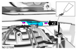
- Apply the substance from the specified tube.
Material: Threadlock and Sealer TA-25.
- Tighten to 55 Nm (41 lb-ft).
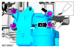
- Apply the substance from the specified tube.
Material: Threadlock and Sealer TA-25.
- Tighten to 55 Nm (41 lb-ft).
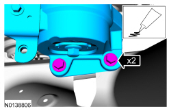
- Apply the substance from the specified tube.
Material: Threadlock and Sealer TA-25.
- Tighten the bolt to 80 Nm (59 lb-ft).
- Tighten the nuts to 63 Nm (46 lb-ft).
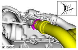
- Align the index marks. Visual check.
- Tighten to 5 Nm (44 lb-in).
- Tighten to 10 Nm (89 lb-in).
- Tighten to 15 Nm (133 lb-in).
- Tighten to 8 Nm (71 lb-in).
- Tighten to 6 Nm (53 lb-in).
- Tighten to 48 Nm (35 lb-ft).
- Tighten to 26 Nm (19 lb-ft).
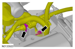
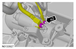
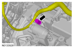
- Tighten the starter battery terminal nut to 12 Nm (106 lb-in).
- Tighten the starter solenoid terminal nut to 6 Nm (53 lb-in).
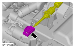
- Install the starter motor positive terminal cover.
- Tighten to 30 Nm (22 lb-ft).
- Install the cowl panel grille. Refer to
Section 501-02
.
- Adjust the selector lever cable. Refer to
Section 307-05
.
- Install the battery tray. Refer to
Section 414-01
.
- Install the
outlet pipe. Refer to
Section 303-12
.
- Fill the transmission with clean transmission fluid. Refer to
Transmission Fluid Drain and Refill
.
- If a new solenoid body is installed, the solenoid body strategy will need to be updated. Refer to
Solenoid Body Strategy Download
.
- After completing the repairs, perform the Misfire Monitor Neutral Profile Correction procedure.


