SECTION 307-05: Automatic Transaxle/Transmission External Controls
2014 Flex Workshop Manual
DIAGNOSIS AND TESTING
Procedure revision date: 05/02/2013

External Controls


Special Tool(s)
Fluke 77-IV Digital Multimeter
FLU77-4 or equivalent
Vehicle Communication Module (VCM) and Integrated Diagnostic System (IDS) software with appropriate hardware, or equivalent scan tool
 

Inspection and Verification

  1. Verify the customer concern by operating the system.
  1. Visually inspect for obvious signs of mechanical or electrical damage.
  1. If an obvious cause for an observed or reported concern is found, correct the cause before proceeding to the next step.
  1. If the concern is not visually evident, verify the symptom. GO to Symptom Chart - External Controls or GO to Symptom Chart - NVH .


  Visual Inspection Chart

Mechanical Electrical
  • Transmission selector lever cable
  • Manual control lever
  • Selector lever or selector lever knob
  • Paddle shifters
  • Fuse 18 (10A)
  • Connections
  • Wiring harness
  • Brake Pedal Position (BPP) switch
  • Brake Shift Interlock Actuator (BSIA)
  • Transmission Control Switch (TCS)
  • Paddle shifters switches


DTC Chart


 DTC Chart

DTC Component Description Condition Symptom Action
B2572 Brake Shift Interlock Actuator (BSIA) Brake shift interlock output circuit failure The associated circuitry connected to the BCM or fuse, or the BCM itself may have an issue causing a BSIA concern. BSIA is inoperative or does not operate correctly. GO to Pinpoint Test A .


Symptom Chart — External Controls

 
Symptom Chart — External Controls
Condition Possible Sources Action
  • Brake shift interlock system does not release/lock correctly
  • Circuitry open/shorted
  • BCM fuse 18 (10A)
  • Brake Pedal Position (BPP) switch
  • Transmission Control Switch (TCS) does not operate correctly
  • Instrument Cluster (IC)
  • Circuitry open/shorted
  • PCM
  • TCS
  • Brake shift interlock system does not release/lock correctly
  • Brake Shift Interlock Actuator (BSIA)
  • INSTALL a new selector lever assembly. REFER to Selector Lever in this section.
    • Transmission Range (TR) sensor
    • Selector lever linkage is out of correct gear relationship
    • Selector lever linkage out of adjustment
      • Loose selector lever cable bracket
      • CHECK the selector lever cable bracket. TIGHTEN as necessary.
      • Select shift does not operate correctly
      • Circuitry open/shorted
      • Paddle shifters
      • PCM
       

      Symptom Chart — NVH

       
      Symptom Chart — NVH

      NOTE: NVH symptoms should be identified using the diagnostic tools that are available. For a list of these tools, an explanation of their uses and a glossary of common terms, refer to Section 100-04 . Since it is possible any one of multiple systems may be the cause of a symptom, it may be necessary to use a process of elimination type of diagnostic approach to pinpoint the responsible system. If this is not the causal system for the symptom, refer back to Section 100-04 for the next likely system and continue diagnosis.

      Condition Possible Sources Action
      • Vibration — a high frequency (20-80 Hz) that is felt through the seat or selector lever. Changes with engine speed
      • Selector lever cable incorrectly routed, grounded out or loose
      • CHECK the selector lever cable. REPAIR as necessary.
       

      Electrical Connectors

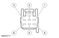
      Selector Lever Harness C3245 (Vehicle Harness Side)


      Pin Number Circuit Circuit Function
      1 CET53 (BU/OG) Brake Shift Interlock Actuator (BSIA) power circuit
      2 CDC41 (WH/BN) PARK detect signal to ignition switch
      3 VLN04 (VT/GY) PARK detect signal to Instrument Cluster (IC)
      4 GD375 (BK/BU) Ground
      5 CET34 (BN/GN) Transmission Control Switch (TCS) signal
      6 CBP30 (YE/BU) TCS power circuit


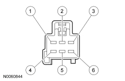
      Selector Lever Harness C3245 (Component Side)


      Pin Number Circuit Circuit Function
      1 OG Brake Shift Interlock Actuator (BSIA) power circuit
      2 RD PARK position signal to ignition switch
      3 BU Power to PRNDL bulb
      4 BK Ground
      5 WH Transmission Control Switch (TCS) signal
      6 BK TCS power circuit


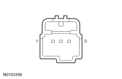
      Paddle Shifter Pinout (Component Side)


      Pin Number Circuit Circuit Function
      1 Upshift signal
      2 Ground supplied from PCM
      3 Downshift signal


      Steering Wheel Wiring Harness Paddle Shifter Circuits

      NOTE: Both RH and LH paddle shifter connectors are the same and share the same circuits.
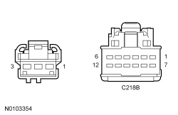


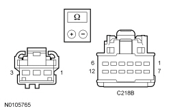
      Paddle Shifter Connector Pin Number Steering Wheel C218B Pin Number Circuit Function (Color)
      1 6 Upshift signal (VT/OG)
      2 2 Ground supplied from PCM (GY)
      3 12 Downshift signal (YE/RD)

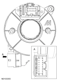
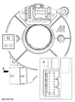
      Clockspring Internal Paddle Shifter Circuits


      Clockspring Pin Number C218B End Component Side Clockspring Pin Number C218A End Component Side Circuit Function
      6 3 Upshift signal
      2 7 Ground supplied from PCM
      12 11 Downshift signal


      Pinpoint Tests

      Refer to Wiring Diagrams Cell 29 , Transmission Controls — 6 Speed for schematic and connector information.

      Refer to Wiring Diagrams Cell 37 , Shift Interlock for schematic and connector information.

       
      PINPOINT TEST A: THE BRAKE SHIFT INTERLOCK SYSTEM DOES NOT RELEASE/LOCK CORRECTLY
      Test Step Result / Action to Take
        A1 TEST THE BRAKE LIGHTS  
      • Apply the brake pedal and view the brake lights.
      • Brake lamps should illuminate within 15 mm (0.59 in) of pedal travel.
      • Do the brake lights illuminate within 15 mm (0.59 in) of pedal travel?
      Yes
      GO to A2 .

      No
      REFER to Section 417-01 .
        A2 TEST BCM FUSE 18 (10A)  
      • Ignition OFF.
      • Check fuse: 18 (10A) .
      • Is the resistance less than 5 ohms?
      Yes
      GO to A3 .

      No
      INSTALL a new fuse. GO to A3 .
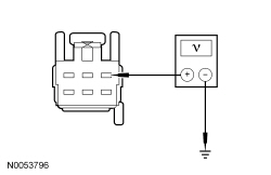
        A3 TEST THE BSIA POWER CIRCUIT  
      • Disconnect: Selector Lever Harness C3245 .
      • Ignition ON.
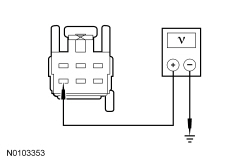
      • Measure the voltage between selector lever harness C3245-1, circuit CET53 (BU/OG) and ground, while applying the brake pedal.


      • Is the voltage greater than 10 volts?
      Yes
      GO to A6 .

      No
      GO to A4 .
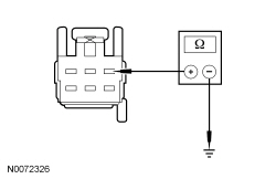
        A4 TEST THE BSIA POWER CIRCUIT FOR A SHORT TO GROUND  
      • Ignition OFF.
      • Disconnect: BCM C2280B .
      • Measure the resistance between selector lever harness C3245-1, circuit CET53 (BU/OG) and ground.


      • Is the resistance greater than 10,000 ohms?
      Yes
      GO to A5 .

      No
      REPAIR circuit CET53 (BU/OG) for a short to ground. TEST the system for normal operation.
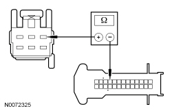
        A5 TEST THE BSIA POWER CIRCUIT FOR AN OPEN  
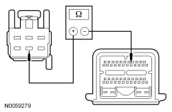
      • Measure the resistance between selector lever harness C3245-1, circuit CET53 (BU/OG) and BCM C2280B -23, circuit CET53 (BU/OG).


      • Is the resistance less than 5 ohms?
      Yes
      INSTALL a new BCM . TEST the system for normal operation.

      No
      REPAIR circuit CET53 (BU/OG) for an open.
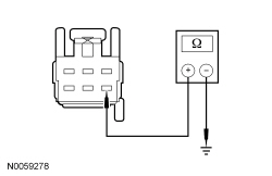
        A6 TEST THE BSIA GROUND CIRCUIT  
      • Ignition OFF.
      • Measure the resistance between selector lever harness C3245-4, circuit GD375 (BK/BU) and ground.


      • Is the resistance less than 5 ohms?
      Yes
      GO to A7 .

      No
      REPAIR circuit GD375 (BK/VT). TEST the system for normal operation.
        A7 TEST THE BSIA WITH THE SELECTOR LEVER CABLE DISCONNECTED  
      • Connect: Selector Lever Harness C3245 .
      • Disconnect the selector lever cable at the selector lever.
      • Ignition ON.
      • Apply the brake pedal and move the selector lever out of the park position.
      • Does the brake shift interlock system release the selector lever correctly?
      Yes
      Check selector cable function and adjust the cable If necessary. REFER to Selector Lever Cable Adjustment In this section.

      No
      INSTALL a new selector lever. REFER to Selector Lever in this section.
       
      PINPOINT TEST B: TCS DOES NOT OPERATE CORRECTLY
      Test Step Result / Action to Take
        B1 TEST THE IC  
      • Connect the scan tool.
      • Using the scan tool, monitor the TCS PID while cycling the Transmission Control Switch (TCS).
      • Does the TCS PID cycle from closed to open?
      Yes
      REFER to Section 413-01 .

      No
      GO to B2 .
        B2 CHECK FOR VOLTAGE SUPPLY AT THE SELECTOR LEVER CONNECTOR  
      • Disconnect: Selector Lever Harness C3245 .
      • Start the engine.
      • Measure the voltage at selector lever C3245-6.


      • Is the voltage greater than 10 volts?
      Yes
      GO to B3 .

      No
      REPAIR circuit CBB46 (WH/BU) for an open. RECONNECT all components. TEST the system for normal operation.
        B3 TEST THE TCS SIGNAL CIRCUIT FOR AN OPEN  
      • Disconnect: PCM C175B .
      • Measure the resistance between selector lever harness C3245-5, circuit CET34 (BN/GN) and PCM C175B-16, circuit CET34 (BN/GN).


      • Is the resistance less than 5 ohms?
      Yes
      GO to B4 .

      No
      REPAIR circuit CET34 (BN/GN) for an open. RECONNECT all components. TEST the system for normal operation.
        B4 TEST THE TCS  
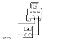
      • Measure the resistance between selector lever C3245-5 and C3245-6, component side, while cycling the TCS .


      • Is the resistance less than 5 ohms when pressed and greater than 10,000 ohms when released?
      Yes
      INSTALL a new PCM. REFER to Section 303-14 . TEST the system for normal operation.

      No
      INSPECT the selector lever wiring harness for damage and REPAIR as necessary. If the selector lever wiring harness is not damaged, INSTALL a new selector lever knob. REFER to Selector Lever Knob in this section. TEST the system for normal operation.
       
      PINPOINT TEST C: SELECT SHIFT DOES NOT OPERATE CORRECTLY
      Test Step Result / Action to Take
        C1 TEST THE PADDLE SHIFTER CIRCUITS FOR AN OPEN  

        NOTE: Both RH and LH paddle shifter connectors are the same and share the same circuits.
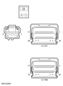
      • Remove the paddle shifter. Refer to Selector Lever — Paddle Shift in this section.
      • For vehicles equipped with a 3.5L engine, disconnect PCM C175B.
      • For vehicles equipped with a 3.5L engine, disconnect PCM C175T.
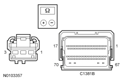
      • For vehicles equipped with a 3.5L Gasoline Turbocharged Direct Injection (GTDI) engine, disconnect PCM C1381B.
      • For vehicles equipped with a 3.5L engine, measure the resistance between the paddle shifter connector, harness side and the PCM C175B and C175T, harness side using the following chart:


      • Paddle Shifter Connector Function/Circuit PCM Connector
        Paddle Shifter Connector Pin 1 Upshift Signal/CET43 (GY) C175T-42
        Paddle Shifter Connector Pin 2 Ground Supply/RE407 (YE/VT) C175B-58
        Paddle Shifter Connector Pin 3 Downshift Signal/CET42 (GN/VT) C175T-44


      • For vehicles equipped with a 3.5L GTDI engine, measure the resistance between the paddle shifter connector, harness side and the PCM C1381B, harness side using the following chart:


      • Paddle Shifter Connector Function/Circuit PCM Connector
        Paddle Shifter Connector Pin 1 Upshift Signal/CET43 (GY) C1381B-23
        Paddle Shifter Connector Pin 2 Ground Supply/RE407 (YE/VT) C1381B-56
        Paddle Shifter Connector Pin 3 Downshift Signal/CET42 (GN/VT) C1381B-24


      • Is the resistance less than 5 ohms?
      Yes
      GO to C4 .

      No
      GO to C2 .
        C2 TEST THE STEERING WHEEL WIRING HARNESS PADDLE SHIFTER CIRCUITS FOR AN OPEN  
      • Disconnect: Steering Wheel Internal Wiring Harness C218B .
      • Measure the resistance between the paddle shifter connector, harness side and the steering wheel internal wiring harness C218B, harness side using the following chart:


      • Paddle Shifter Connector Pin Number Circuit Function (Color) Steering Wheel C218B Pin Number
        1 Upshift signal (VT/OG) 6
        2 Ground supplied from PCM (GY) 2
        3 Downshift signal (YE/RD) 12


      • Is the resistance less than 5 ohms?
      Yes
      GO to C3 .

      No
      INSTALL a new steering wheel. REFER to Section 211-04 .
        C3 TEST THE CLOCKSPRING INTERNAL PADDLE SHIFTER CIRCUITS FOR AN OPEN  
      • Remove the steering column shroud. Refer to Section 211-04 .
      • Disconnect: Clockspring C218A .
      • Measure the resistance of the paddle shifter circuits through the clockspring, using the following chart:


      • Clockspring Pin Number C218B End Component Side Circuit Function Clockspring Pin Number C218A End Component Side
        6 Upshift signal 3
        2 Ground supplied from PCM 7
        12 Downshift signal 11


      • Is the resistance less than 5 ohms?
      Yes
      REPAIR the circuit in question between clockspring C218A and the PCM connector for an open.

      No
      INSTALL a new clockspring. REFER to Section 501-20B .
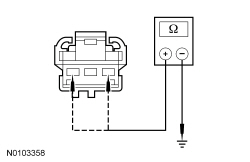
        C4 TEST THE PADDLE SHIFTER SIGNAL CIRCUITS FOR A SHORT TO GROUND  
      • Measure the resistance between the paddle shifter connector, harness side and ground using the following chart:


      • Paddle Shifter Connector Function/Circuit
        Paddle Shifter Connector Pin 1 Upshift Signal/CET43 (GY)
        Paddle Shifter Connector Pin 3 Downshift Signal/CET42 (GN/VT)


      • Is the resistance greater than 10,000 ohms?
      Yes
      GO to C6 .

      No
      GO to C5 .
        C5 TEST THE STEERING WHEEL WIRING HARNESS PADDLE SHIFTER SIGNAL CIRCUITS FOR A SHORT TO GROUND  
      • Disconnect: Steering Wheel Internal Wiring Harness C218B .
      • Measure the resistance between the paddle shifter connector, harness side and ground using the following chart:


      • Paddle Shifter Connector Function/Circuit
        Paddle Shifter Connector Pin 1 Upshift Signal/CET43 (GY)
        Paddle Shifter Connector Pin 3 Downshift Signal/CET42 (GN/VT)


      • Is the resistance greater than 10,000 ohms?
      Yes
      REPAIR the circuit in question between clockspring C218A and the PCM connector for a short.

      No
      INSTALL a new steering wheel. REFER to Section 211-04 .
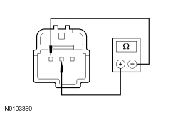
        C6 CHECK THE PADDLE SHIFTER  
      • Measure the resistance between the pins 2 and 1, component side while cycling the paddle shifter to the upshift position.


      • Measure the resistance between the pins 2 and 3, component side while cycling the paddle shifter to the downshift position.


      • Is the resistance less than 5 ohms when the paddle shifter is in the shift position and greater than 10,000 ohms when the paddle shifter is released?
      Yes
      INSTALL a new PCM. REFER to Section 303-14 . RECONNECT all components. TEST the system for normal operation.

      No
      INSTALL a new paddle shifter. REFER to Selector Lever — Paddle Shift in this section.