SECTION 419-01A: Anti-Theft — Perimeter
| 2014 Flex Workshop Manual
|
DIAGNOSIS AND TESTING
| Procedure revision date: 05/02/2013
|
Anti-Theft — With Intelligent Access (IA)
DTC Chart
Diagnostics in this manual assume a certain skill level and knowledge of Ford-specific diagnostic practices. Refer to Diagnostic Methods in
Section 100-00
for information about these practices.
DTC Chart
Symptom Chart
Diagnostics in this manual assume a certain skill level and knowledge of Ford-specific diagnostic practices. Refer to Diagnostic Methods in
Section 100-00
for information about these practices.
Symptom Chart — Perimeter Alarm With
| Condition
| Possible Sources
| Action
|
|---|
- The alarm system does not activate from an unauthorized entry at the hood
| - Refer to the Diagnostic Routine
| |
- The alarm system does not activate from an unauthorized entry at a door
| | - REFER to
Section 417-02
to diagnose the courtesy lamps not illuminating when a door is open.
|
- The alarm system does not activate from an unauthorized entry at the liftgate
| | - REFER to
Section 417-02
to diagnose the courtesy lamps not illuminating when the liftgate is open.
|
- The alarm system does not arm or no turn signal flash confirmation
| - Refer to the Diagnostic Routine
| |
- No horn output during alarm activation
| | |
| - Door ajar input
- Hood ajar input
- Liftgate ajar input
- Panic button pressed on an
transmitter
- A valid
key read is NOT received when the ignition transitions to RUN
| - An intermittent fault exists. MONITOR the
alarm event
to identify and isolate the cause of the last alarm activation.
- Most recent alarm trigger event (ALARM_EVT_1).
- Second most recent alarm trigger event (ALARM_EVT_2).
- Third most recent alarm trigger event (ALARM_EVT_3).
- Fourth most recent alarm trigger event (ALARM_EVT_4).
|
Pinpoint Tests
Pinpoint Test D: The Alarm System Does Not Activate From An Unauthorized Entry At The Hood
Diagnostic Overview
Diagnostics in this manual assume a certain skill level and knowledge of Ford-specific diagnostic practices. Refer to Diagnostic Methods in
Section 100-00
for information about these practices.
Refer to Wiring Diagrams Cell
117
, Remote Keyless Entry and Alarm for schematic and connector information.
Normal Operation and Fault Conditions
Refer to System Operation, Perimeter Alarm Activation in
Anti-Theft — With Intelligent Access (IA)
.
Refer to Component Description, Hood Ajar Switch in
Anti-Theft — With Intelligent Access (IA)
.
Possible Sources
- Wiring, terminals or connectors
- Hood ajar switch
Visual Inspection and Diagnostic Pre-checks
- Inspect the hood ajar switch for damage.
PINPOINT TEST D: THE ALARM SYSTEM DOES NOT ACTIVATE FROM AN UNAUTHORIZED ENTRY AT THE HOOD
| Test Step
| Result / Action to Take
|
|---|
|
D1 RETRIEVE THE RECORDED DTCs IN THE BCM
|
|
NOTE:
B1305:01 sets if the hood is open during the
on-demand self-test. Make sure the hood is closed prior to running the
self-test.
- Ignition ON.
- Using a scan tool, perform the
on-demand self-test.
- Is
B1305:01 present?
| Yes
GO to Pinpoint Test F
.
No
GO to
D2
.
|
|
D2 MONITOR THE
HOOD AJAR SWITCH (HOOD_SW)
|
|
- Using a scan tool, view
.
- Using a scan tool, monitor the
HOOD_SW
.
- Disconnect: Hood Ajar Switch C127.
- Does the
read AJAR when the switch is disconnected?
| Yes
INSTALL a new hood ajar switch.
No
GO to
D3
.
|
|
D3 CHECK THE HOOD AJAR SWITCH INPUT CIRCUIT FOR A SHORT TO GROUND
|
|
- Ignition OFF.
- Disconnect:
C2280F.
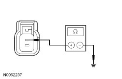
- Measure the resistance between the hood switch C127-1, circuit CPL25 (BU/OG), harness side and ground.
 - Is the resistance greater than 10,000 ohms?
| Yes
GO to
D4
.
No
REPAIR the circuit.
|
|
D4 CHECK FOR CORRECT
OPERATION
|
|
- Disconnect and inspect all the
connectors.
- Repair:
- corrosion (install new connector or terminals – clean module pins)
- damaged or bent pins – install new terminals/pins
- pushed-out pins – install new pins as necessary
- Reconnect the
connectors. Make sure they seat correctly.
- Operate the system and determine if the concern is still present.
- Is the concern still present?
| Yes
CHECK On-Line Automotive Service Information System (OASIS) for any applicable
. If a
exists for this concern, DISCONTINUE this test and FOLLOW
instructions. If no
address this concern, INSTALL a new
. REFER to
Section 419-10
.
No
The system is operating correctly at this time. The concern may have been caused by module connections. ADDRESS the root cause of any connector or pin issues.
|
Pinpoint Test E: The Alarm System Does Not Arm Or No Turn Signal Flash Confirmation
Diagnostic Overview
Diagnostics in this manual assume a certain skill level and knowledge of Ford-specific diagnostic practices. Refer to Diagnostic Methods in
Section 100-00
for information about these practices.
Refer to Wiring Diagrams Cell
117
, Remote Keyless Entry and Alarm for schematic and connector information.
Normal Operation and Fault Conditions
Refer to System Operation, Perimeter Alarm in
Anti-Theft — With Intelligent Access (IA)
.
Refer to System Operation, Arming the Perimeter Alarm in
Anti-Theft — With Intelligent Access (IA)
.
Possible Sources
- Door ajar input
- Hood ajar input
- Liftgate ajar input
- Turn signal output
- Keyless entry keypad concern
- transmitter concern
Visual Inspection and Diagnostic Pre-checks
- Inspect the hood ajar switch for damage.
PINPOINT TEST E: THE ALARM SYSTEM DOES NOT ARM OR NO TURN SIGNAL FLASH CONFIRMATION
| Test Step
| Result / Action to Take
|
|---|
|
E1 RETRIEVE THE RECORDED DTCs FROM THE
|
|
- Ignition ON.
- Using a scan tool, perform the
self-test.
- Is DTC B1305:01 present?
| Yes
GO to Pinpoint Test F
.
No
GO to
E2
.
|
|
E2 CHECK THE DOOR AJAR INPUT
|
|
- Close all the doors.
- Observe the
.
- Does the
indicate a door is ajar?
| Yes
REFER to
Section 417-02
to diagnose the courtesy lamps staying on continuously.
No
GO to
E3
.
|
|
E3 MONITOR THE LIFTGATE AJAR MESSAGE/INDICATOR IN THE
|
|
- Ignition ON.
- Close the liftgate.
- Open the liftgate while monitoring the
.
- Does the
indicate the liftgate is ajar?
| Yes
REFER to
Section 417-02
to diagnose the courtesy lamps staying on continuously.
No
GO to
E4
.
|
|
E4 CHECK THE HAZARD LAMP OPERATION
|
|
- Ignition OFF.
- Activate the hazard flasher lamp function and observe the turn signals.
- Does the all the turn signals flash on and off?
| Yes
GO to
E5
.
No
REFER to
Section 417-01
to diagnose the inoperative turn signals.
|
|
E5 CHECK THE
TRANSMITTER FUNCTION
|
|
- Using the
transmitter, lock and unlock the doors.
- Do the doors lock and unlock?
| Yes
GO to
E6
.
No
REFER
Section 501-14B
to diagnose the inoperative
transmitter.
|
|
E6 CHECK THE KEYLESS ENTRY KEYPAD FUNCTION
|
|
- Using the keyless entry keypad, lock the doors (touch 7/8 and 9/0).
- Do the doors lock?
| Yes
GO to
E7
.
No
REFER
Section 501-14B
to diagnose the keyless entry keypad.
|
|
E7 CHECK FOR CORRECT
OPERATION
|
|
- Disconnect and inspect all the
connectors.
- Repair:
- corrosion (install new connector or terminals – clean module pins)
- damaged or bent pins – install new terminals/pins
- pushed-out pins – install new pins as necessary
- Reconnect the
connectors. Make sure they seat correctly.
- Operate the system and determine if the concern is still present.
- Is the concern still present?
| Yes
CHECK On-Line Automotive Service Information System (OASIS) for any applicable
. If a
exists for this concern, DISCONTINUE this test and FOLLOW
instructions. If no
address this concern, INSTALL a new
. REFER to
Section 419-10
.
No
The system is operating correctly at this time. The concern may have been caused by module connections. ADDRESS the root cause of any connector or pin issues.
|
Pinpoint Test F: B1305:01
Diagnostic Overview
Diagnostics in this manual assume a certain skill level and knowledge of Ford-specific diagnostic practices. Refer to Diagnostic Methods in
Section 100-00
for information about these practices.
Refer to Wiring Diagrams Cell
117
, Remote Keyless Entry and Alarm for schematic and connector information.
Normal Operation and Fault Conditions
Refer to Component Description, Hood Ajar Switch in
Anti-Theft — With Intelligent Access (IA)
.
Refer to System Operation, Perimeter Alarm in
Anti-Theft — With Intelligent Access (IA)
.
DTC Fault Trigger Conditions
| DTC
| Description
| Fault Trigger Conditions
|
|---|
| Hood Switch: General Electrical Failure
| Sets when the
detects an open from the hood ajar input circuit or when the hood is open during the
self-test.
|
Possible Sources
- Wiring, terminals or connectors
- Hood ajar switch
Visual Inspection and Diagnostic Pre-checks
- Inspect the hood ajar switch for damage.
PINPOINT TEST F: B1305:01
| Test Step
| Result / Action to Take
|
|---|
|
F1 CHECK THE HOOD AJAR SWITCH
|
|
- Disconnect: Hood Ajar Switch C127.
- Ignition ON.
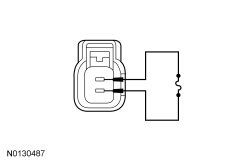
- Connect a fused jumper wire between the hood ajar switch C127-1, circuit CPL25 (BU/OG), harness side and the hood ajar switch C127-2, circuit GD120 (BK/GN), harness side.
 - Using a scan tool, perform the
self-test.
- Is DTC B1305:01 still present?
| Yes
REMOVE the jumper wire. GO to
F2
.
No
REMOVE the jumper wire. INSTALL a new hood ajar switch.
|
|
F2 CHECK THE HOOD AJAR SWITCH GROUND CIRCUIT FOR AN OPEN
|
|
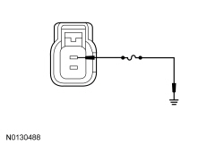
- Connect a fused jumper wire between the hood ajar switch C127-1, circuit CPL25 (BU/OG), harness side and ground.
 - Using a scan tool, perform the
self-test.
- Is DTC B1305:01 still present?
| Yes
REMOVE the jumper wire. GO to
F3
.
No
REMOVE the jumper wire. REPAIR the circuit.
|
|
F3 CHECK THE HOOD AJAR SWITCH INPUT CIRCUIT FOR AN OPEN
|
|
- Ignition OFF.
- Disconnect:
C2280F.
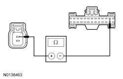
- Measure the resistance between the hood ajar switch C127-1, circuit CPL25 (BU/OG), harness side and
C2280F-2, circuit CPL25 (BU/OG), harness side.
 - Is the resistance less than 3 ohms?
| Yes
GO to
F4
.
No
REPAIR the circuit.
|
|
F4 CHECK FOR CORRECT
OPERATION
|
|
- Disconnect and inspect all the
connectors.
- Repair:
- corrosion (install new connector or terminals – clean module pins)
- damaged or bent pins – install new terminals/pins
- pushed-out pins – install new pins as necessary
- Reconnect the
connectors. Make sure they seat correctly.
- Operate the system and determine if the concern is still present.
- Is the concern still present?
| Yes
CHECK On-Line Automotive Service Information System (OASIS) for any applicable
. If a
exists for this concern, DISCONTINUE this test and FOLLOW
instructions. If no
address this concern, INSTALL a new
. REFER to
Section 419-10
.
No
The system is operating correctly at this time. The concern may have been caused by module connections. ADDRESS the root cause of any connector or pin issues.
|


