SECTION 419-01C: Anti-Theft — Passive Anti-Theft System (PATS), With Intelligent Access (IA)
| 2014 Flex Workshop Manual
|
DIAGNOSIS AND TESTING
| Procedure revision date: 06/04/2013
|
Anti-Theft
Charts
Diagnostics in this manual assume a certain skill level and knowledge of Ford-specific diagnostic practices. Refer to Diagnostic Methods in
Section 100-00
for information about these practices.
Module DTC Chart
PCM DTC Chart
Symptom Chart
Diagnostics in this manual assume a certain skill level and knowledge of Ford-specific diagnostic practices. Refer to Diagnostic Methods in
Section 100-00
for information about these practices.
Symptom Chart
| Condition
| Possible Sources
| Action
|
|---|
- The vehicle does not start with the IA key in certain areas within the vehicle
| - Refer to the Diagnostic Routine
| |
- The engine does not start or unable to turn ignition on
| - Refer to the Diagnostic Routine
| |
- STARTING SYSTEM FAULT is displayed in the message center
| | - RETRIEVE and DIAGNOSE all
DTCs in the
module and the PCM. REFER to the
Module DTC Chart or the PCM DTC Chart in this section.
|
- NO KEY DETECTED is displayed in the message center
| - Refer to the Diagnostic Routine
| |
Pinpoint Tests
Pinpoint Test A: The Vehicle Does Not Start With the
Key in Certain Areas of the Vehicle
Diagnostic Overview
Diagnostics in this manual assume a certain skill level and knowledge of Ford-specific diagnostic practices. Refer to Diagnostic Methods in
Section 100-00
for information about these practices.
Refer to Wiring Diagrams Cell
112
, Passive Anti-Theft System for schematic and connector information.
NOTE:
Some brands/types of mobile phone or laptop computer chargers may cause interference that could lead to a
no-start if the
key is within a few inches of the charger. If a concern is observed, move the
key away from the charger and attempt to start the vehicle.
Normal Operation and Fault Conditions
Refer to System Operation - Passive Anti-Theft System (PATS) in
Anti-Theft
.
Refer to Component Description - Passive Start Antennas in
Anti-Theft
.
Module DTC Fault Trigger Conditions
| DTC
| Description
| Fault Trigger Conditions
|
|---|
| B10C7:01
| Interior Trunk Antenna: General Electrical Failure
| Sets when the
module detects an open, short to ground, or short to voltage from one of the circuits to the rear passive start antenna.
|
| B10C8:01
| Interior Centre Antenna: General Electrical Failure
| Sets when the
module detects an open, short to ground, or short to voltage from one of the circuits to the center passive start antenna.
|
| B10C9:01
| Interior Front Antenna: General Electrical Failure
| Sets when the
module detects an open, short to ground, or short to voltage from one of the circuits to the front passive start antenna.
|
Possible Sources
- Wiring, terminals or connectors
- Passive start antenna
- module
PINPOINT TEST A: THE VEHICLE DOES NOT START WITH THE
KEY IN CERTAIN AREAS OF THE VEHICLE
| Test Step
| Result / Action to Take
|
|---|
|
A1 CHECK THE
KEY LOCATION
|
|
- Ignition ON.
- Check the location of the
key. If it is placed in the far corners of the interior of the vehicle, move the
key out of these areas and attempt to start the vehicle.
- Does the vehicle start?
| Yes
The system is operating correctly. INFORM the customer of the correct operation of the
feature.
No
GO to
A2
.
|
|
A2 CHECK FOR ENVIRONMENTAL INTERFERENCE
|
|
- Check for the use of any charger or other wireless device that can cause interference with the
key. If any device is found, remove the device and attempt to start the vehicle.
- Does the vehicle start?
| Yes
The system is operating correctly. INFORM the customer of the cause of the concern and the correct operation of the
feature.
No
GO to
A3
.
|
|
A3 CHECK THE SUSPECT PASSIVE START ANTENNA
|
|
- Ignition OFF.
- Disconnect: Suspect Passive Start Antenna .
- Measure the resistance between the suspect passive start antenna pin 1, component side and suspect passive start antenna pin 2, component side.
 - Is the resistance between 0.3 and 0.6 ohms?
| Yes
GO to
A4
.
No
INSTALL a new passive start antenna for the one in question.
|
|
A4 CHECK THE PASSIVE START ANTENNA CIRCUITS FOR A SHORT TO VOLTAGE
|
|
- Disconnect:
Module C2153A .
- Place an
key in the backup transceiver slot and press the start/stop switch to transition the ignition to RUN.
- Measure the voltage between the suspect passive start antenna, harness side and ground as follows:
| Suspect Passive Start Antenna
| Connector-Pin
| Circuit
|
|---|
| Front
| C325-1
| VPK05 (BN/GN)
| | Front
| C325-2
| RPK05 (YE/OG)
| | Center
| C326-1
| VPK06 (GY/VT)
| | Center
| C326-2
| RPK06 (BU/WH)
| | Rear
| C4321-1
| VPK08 (WH/OG)
| | Rear
| C4321-2
| RPK08 (BN/VT)
|
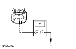 - Is any voltage present?
| Yes
REPAIR the circuit in question.
No
GO to
A5
.
|
|
A5 CHECK THE PASSIVE START ANTENNA CIRCUITS FOR A SHORT TO GROUND
|
|
- Ignition OFF.
- Measure the resistance between the suspect passive start antenna, harness side and ground as follows:
| Suspect Passive Start Antenna
| Connector-Pin
| Circuit
|
|---|
| Front
| C325-1
| VPK05 (BN/GN)
| | Front
| C325-2
| RPK05 (YE/OG)
| | Center
| C326-1
| VPK06 (GY/VT)
| | Center
| C326-2
| RPK06 (BU/WH)
| | Rear
| C4321-1
| VPK08 (WH/OG)
| | Rear
| C4321-2
| RPK08 (BN/VT)
|
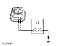 - Are the resistances greater than 10,000 ohms?
| Yes
GO to
A6
.
No
REPAIR the circuit in question.
|
|
A6 CHECK THE PASSIVE START ANTENNA CIRCUITS FOR AN OPEN
|
|
- Measure the resistance between the suspect passive start antenna, harness side and the
module, harness side as follows:
Suspect Passive Start Antenna
Connector-Pin
| Circuit
| Module
Connector-Pin
|
|---|
Front
C325-1
| VPK05 (BN/GN)
| C2153A-1
| Front
C325-2
| RPK05 (YE/OG)
| C2153A-2
| Center
C326-1
| VPK06 (GY/VT)
| C2153A-3
| Center
C326-2
| RPK06 (BU/WH)
| C2153A-4
| Rear
C4321-1
| VPK08 (WH/OG)
| C2153A-5
| Rear
C4321-2
| RPK08 (BN/VT)
| C2153A-14
|
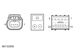 - Are the resistances less than 3 ohms?
| Yes
GO to
A7
.
No
REPAIR the circuit in question.
|
|
A7 CHECK FOR CORRECT
MODULE OPERATION
|
|
- Disconnect and inspect all the
module connectors.
- Repair:
- corrosion (install new connector or terminals – clean module pins)
- damaged or bent pins – install new terminals/pins
- pushed-out pins – install new pins as necessary
- Reconnect the
module connectors. Make sure they seat correctly.
- Operate the system and determine if the concern is still present.
- Is the concern still present?
| Yes
CHECK On-Line Automotive Service Information System (OASIS) for any applicable
. If a
exists for this concern, DISCONTINUE this test and FOLLOW
instructions. If no
address this concern, INSTALL a new
module. REFER to
Section 419-10
.
No
The system is operating correctly at this time. The concern may have been caused by module connections. ADDRESS the root cause of any connector or pin issues.
|
Pinpoint Test B: The Engine Does Not Start or Unable To Turn Ignition On
Diagnostic Overview
Diagnostics in this manual assume a certain skill level and knowledge of Ford-specific diagnostic practices. Refer to Diagnostic Methods in
Section 100-00
for information about these practices.
Refer to Wiring Diagrams Cell
112
, Passive Anti-Theft System for schematic and connector information.
Normal Operation and Fault Conditions
Refer to System Operation - Passive Anti-Theft System (PATS) in
Anti-Theft
.
Refer to System Operation - Backup Starting in
Anti-Theft
.
Refer to Component Description - Passive Start Antennas in
Anti-Theft
.
Possible Sources
- Starting system concern
- Driveability concern
- concern
PINPOINT TEST B: THE ENGINE DOES NOT START OR UNABLE TO TURN IGNITION ON
NOTE:
The
feature is a programmable parameter and can be enabled/disabled with a scan tool. If the feature is disabled, the
feature to enter the vehicle and passive starting are inoperative. To start the vehicle, the
key has to be placed in the backup transceiver slot.
| Test Step
| Result / Action to Take
|
|---|
|
B1 CHECK FOR MESSAGES IN THE MESSAGE CENTER
|
|
- Check the message center while pressing the start/stop switch.
- Is NO KEY DETECTED displayed in the message center?
| Yes
GO to Pinpoint Test C
.
No
GO to
B2
.
|
|
B2 CHECK THE
OPERATION
|
|
- Observe the
operation while pressing the start/stop switch.
- Do some of the indicators in the
illuminate?
| Yes
GO to
B3
.
No
GO to
B4
.
|
|
B3 CHECK FOR
MODULE AND PCM DTCs
|
|
- Using a scan tool, perform the
module and PCM self-test.
- Are any
module or PCM DTCs present?
| Yes
REFER to the
Module DTC Chart or PCM DTC Chart in this section.
No
The no-crank condition is not
-related. REFER to
Section 303-06
.
|
|
B4 CHECK FOR COMMUNICATION WITH THE SCAN TOOL
|
|
- Refer to
Section 418-00
and follow the procedure to establish a session with the vehicle.
- Does the scan tool establish communication with the
and the
module?
| Yes
REFER to
Section 211-05
to diagnose no power in RUN-no power in START.
No
REFER to
Section 418-00
to diagnose the
or the
module not responding to the scan tool.
|
Pinpoint Test C: NO KEY DETECTED Message Is Displayed In The Message Center
Diagnostic Overview
Diagnostics in this manual assume a certain skill level and knowledge of Ford-specific diagnostic practices. Refer to Diagnostic Methods in
Section 100-00
for information about these practices.
Normal Operation and Fault Conditions
Refer to System Operation - NO KEY DETECTED Message in
Anti-Theft
.
Possible Sources
- Environmental interference
- key
- key battery
- key not programmed
PINPOINT TEST C: NO KEY DETECTED MESSAGE IS DISPLAYED IN THE MESSAGE CENTER
NOTE:
This pinpoint test may require a second
key. If only one key is available, a second
key must be obtained.
| Test Step
| Result / Action to Take
|
|---|
|
C1 CHECK FOR
MODULE DTCs
|
|
- Ignition ON.
- Using a diagnostic scan tool, perform the
module self-test.
- Are any DTCs present?
| Yes
DIAGNOSE the
module DTCs. REFER to
Module DTC Chart in this section.
No
If the concern is still present, GO to
C2
.
If concern is no longer present, the system is operating normally at this time. The concern may have been caused due to an intermittent fault condition.
|
|
C2 CHECK THE
KEY
TRANSMITTER OPERATION
|
|
- Press the lock and unlock buttons on the suspect
key.
- Do the doors lock and unlock?
| Yes
GO to
C3
.
No
REFER to
Section 501-14B
to diagnose the inoperative
transmitter concern.
|
|
C3 CHECK THE IA KEY LOCATION
|
|
- Place the
key in several locations within the vehicle and attempt to start the vehicle.
- Does the vehicle start with the
key in certain areas only?
| Yes
GO to Pinpoint Test A
.
No
GO to
C4
.
|
|
C4 CHECK FOR ENVIRONMENTAL INTERFERENCE
|
|
- Check for the use of any charger or other wireless device that can cause interference with the
key. If any device is found, remove the device and attempt to start the vehicle.
- Does the vehicle start?
| Yes
The vehicle is operating correctly. INFORM the customer of the cause of the concern and the normal operation of the
feature.
No
GO to
C5
.
|
|
C5 CHECK THE IA KEY PROGRAMMING
|
|
| Yes
The concern was caused by an unprogrammed
key.
No
DISCARD the key in question and PROGRAM a new
key. REFER to
Key Programming Using Diagnostic Equipment
.
|
Pinpoint Test D: B10D7:05
Diagnostic Overview
Diagnostics in this manual assume a certain skill level and knowledge of Ford-specific diagnostic practices. Refer to Diagnostic Methods in
Section 100-00
for information about these practices.
Refer to Wiring Diagrams Cell
112
, Passive Anti-Theft System for schematic and connector information.
Normal Operation and Fault Conditions
When the
module enters a key programming state, it activates the backup transceiver to read the key in the backup transceiver slot. When a valid
key is used and there are no concerns with the
, the key is programmed into the
module memory.
Module DTC Fault Trigger Conditions
| DTC
| Description
| Fault Trigger Conditions
|
|---|
| B10D7:05
| PATS Key: System Programming Failure
| Sets when the
module has not successfully programmed an
key into the
module when in the key programming state.
|
Possible Sources
- key
- key not programmed
Visual Inspection and Diagnostic Pre-checks
- Inspect the
key for physical damage.
PINPOINT TEST D: B10D7:05
NOTE:
This pinpoint test may require a second
key. If only one key is available, a second
key must be obtained.
| Test Step
| Result / Action to Take
|
|---|
|
D1 REVIEW THE
MODULE DTCs FROM THE ON-DEMAND SELF-TEST
|
|
- Review the
module DTCs from the on-demand self-test.
- Are any other
module DTCs present?
| Yes
REFER to the
Module DTC Chart in this section.
No
GO to
D2
.
|
|
D2 CHECK THE
KEYS
|
|
- Verify the correct
keys are used with the vehicle.
- Are the correct keys used?
| Yes
ATTEMPT to program the key again. REFER to
Key Programming Using Diagnostic Equipment
.
If the key programming fails, GO to
D3
.
No
OBTAIN the correct key(s) for the vehicle. PROGRAM the new key(s). REFER to
Key Programming Using Diagnostic Equipment
.
|
|
D3 CHECK BOTH
KEYS
|
|
| Yes
REPLACE the
key that did not program. PROGRAM the new
key. REFER to
Key Programming Using Diagnostic Equipment
.
No
If the vehicle started with both
keys, the vehicle is operating correctly. The concern was cause by an unprogrammed
key.
If neither
key starts the vehicle, INSTALL a new backup transceiver. REFER to
Backup Transceiver
. PROGRAM the
keys. REFER to
Key Programming Using Diagnostic Equipment
.
|
Pinpoint Test E: B10D9:11, B10D9:12, B10D9:31 Or B10D9:87
Diagnostic Overview
Diagnostics in this manual assume a certain skill level and knowledge of Ford-specific diagnostic practices. Refer to Diagnostic Methods in
Section 100-00
for information about these practices.
Refer to Wiring Diagrams Cell
112
, Passive Anti-Theft System for schematic and connector information.
Normal Operation and Fault Conditions
The
module uses the backup transceiver to operate the
in the event of a failure of any passive start antenna, a discharged battery in the
key, or a communication concern with the
module. The backup transceiver is also used for
key programming.
The backup transceiver receives voltage and ground directly from the
module. The
module controls the backup transceiver through the dedicated clock and data circuits.
Module DTC Fault Trigger Conditions
| DTC
| Description
| Fault Trigger Conditions
|
|---|
| B10D9:11
| PATS Transponder: Circuit Short to Ground
| Sets when the
module detects a short to ground from the transceiver voltage supply circuit.
|
| B10D9:12
| PATS Transponder: Circuit Short to Battery
| Sets when the
module detects a short to voltage from the transceiver voltage supply circuit.
|
| B10D9:31
| PATS Transponder: No Signal
| Sets when the
module does not receive a signal from the backup transceiver.
|
| B10D9:87
| PATS Transponder: Missing Message
| Sets when the
module cannot initialize the backup transceiver.
|
Possible Sources
- Wiring, terminals or connectors
- Backup transceiver
- module
PINPOINT TEST E: B10D9:11, B10D9:12, B10D9:31 OR B10D9:87
| Test Step
| Result / Action to Take
|
|---|
|
E1 CHECK THE BACKUP TRANSCEIVER CIRCUITS FOR A SHORT TO VOLTAGE
|
|
- Ignition OFF.
- Disconnect:
Module C2153D .
- Disconnect: Backup Transceiver C3371 .
- Ignition ON.
- Measure the voltage between the backup transceiver, harness side and ground as follows:
| Backup Transceiver Connector-Pin
| Circuit
|
|---|
| C3371-2
| LPK32 (GN/BU)
| | C3371-3
| VPK32 (WH/BU)
| | C3371-4
| VPK33 (WH)
| | C3371-5
| RPK32 (YE/GY)
|
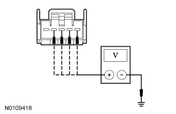 - Is any voltage present?
| Yes
REPAIR the circuit in question.
No
GO to
E2
.
|
|
E2 CHECK THE BACKUP TRANSCEIVER CIRCUITS FOR A SHORT TO GROUND
|
|
- Ignition OFF.
- Measure the resistance between the backup transceiver, harness side and ground as follows:
| Backup Transceiver Connector-Pin
| Circuit
|
|---|
| C3371-2
| LPK32 (GN/BU)
| | C3371-3
| VPK32 (WH/BU)
| | C3371-4
| VPK33 (WH)
| | C3371-5
| RPK32 (YE/GY)
|
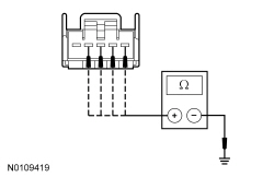 - Are the resistances greater than 10,000 ohms?
| Yes
GO to
E3
.
No
REPAIR the circuit in question.
|
|
E3 CHECK THE BACKUP TRANSCEIVER CIRCUITS FOR AN OPEN
|
|
- Measure the resistance between the backup transceiver, harness side and
module, harness side as follows:
| Backup Transceiver Connector-Pin
| Circuit
| Module Connector-Pin
|
|---|
| C3371-2
| LPK32 (GN/BU)
| C2153D-11
| | C3371-3
| VPK32 (WH/BU)
| C2153D-13
| | C3371-4
| VPK33 (WH)
| C2153D-12
| | C3371-5
| RPK32 (YE/GY)
| C2153D-14
|
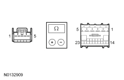 - Are the resistances less than 3 ohms?
| Yes
INSTALL a new backup transceiver. REFER to
Backup Transceiver
. TEST the system for normal operation.
If the concern is still present, GO to
E4
.
No
REPAIR the circuit in question.
|
|
E4 CHECK FOR CORRECT
MODULE OPERATION
|
|
- Disconnect and inspect all the
module connectors.
- Repair:
- corrosion (install new connector or terminals – clean module pins)
- damaged or bent pins – install new terminals/pins
- pushed-out pins – install new pins as necessary
- Reconnect the
module connectors. Make sure they seat correctly.
- Operate the system and determine if the concern is still present.
- Is the concern still present?
| Yes
CHECK On-Line Automotive Service Information System (OASIS) for any applicable
. If a
exists for this concern, DISCONTINUE this test and FOLLOW
instructions. If no
address this concern, INSTALL a new
module. REFER to
Section 419-10
.
No
The system is operating correctly at this time. The concern may have been caused by module connections. ADDRESS the root cause of any connector or pin issues.
|


