SECTION 419-03A: Cruise Control — Non-Adaptive
| 2014 Flex Workshop Manual
|
DIAGNOSIS AND TESTING
| Procedure revision date: 05/02/2013
|
Cruise Control
DTC Charts
Diagnostics in this manual assume a certain skill level and knowledge of Ford-specific diagnostic practices. Refer to Diagnostic Methods in
Section 100-00
for information about these practices.
PCM DTC Chart
DTC Chart
Symptom Chart
Diagnostics in this manual assume a certain skill level and knowledge of Ford-specific diagnostic practices. Refer to Diagnostic Methods in
Section 100-00
for information about these practices.
Symptom Chart
| Condition
| Possible Sources
| Action
|
|---|
- The cruise control is inoperative
| - Refer to the Diagnostic Routine
| |
- The cruise control indicator lamp is never/always on
| - Wiring, terminals and connectors
- PCM
| |
- The cruise control switch is inoperative/does not operate correctly
| - Refer to the Diagnostic Routine
| |
- The cruise control cannot set above 105 kmh (65 mph), 113 kmh (70 mph), 121 kmh (75 mph), or 129 kmh (80 mph)
| - A MyKey® restricted key is in use and MyKey® maximum speed limiter is turned ON
| - VERIFY if a MyKey® restricted key is in use. With an admin key, VERIFY if MyKey® maximum speed limiter is on. REFER to the Owner's Literature. If necessary, VERIFY cruise control normal operation with an admin key.
|
Pinpoint Tests
Pinpoint Test A: The Cruise Control Is Inoperative
Diagnostic Overview
Diagnostics in this manual assume a certain skill level and knowledge of Ford-specific diagnostic practices. Refer to Diagnostic Methods in
Section 100-00
for information about these practices.
Normal Operation and Fault Conditions
Refer to Cruise Control Operation in
Cruise Control
.
Refer to Steering Wheel Switch Function in
Cruise Control
.
Refer to Steering Wheel Switches in
Section 211-05
.
Possible Sources
- Wiring, terminals and connectors
- PCM not configured for cruise control
- Cruise control switch
- Digital
sensor
- Vehicle speed signal
- PCM
PINPOINT TEST A: THE CRUISE CONTROL IS INOPERATIVE
| Test Step
| Result / Action to Take
|
|---|
|
A1 CHECK FOR PCM DTCs
|
|
- Using a scan tool, perform the PCM
self-test.
- Are any DTCs recorded?
| Yes
REFER to DTC Charts in this section.
No
GO to
A2
.
|
|
A2 CHECK FOR
DTCs
|
|
- Using a scan tool, perform the
self-test.
- Are any
DTCs recorded?
| Yes
REFER to
Section 211-05
.
No
GO to
A3
.
|
|
A3 CHECK THE BRAKE PEDAL POSITION SWITCH (BOO1) AND CRUISE CONTROL DEACTIVATOR SWITCH (BOO2) PIDs
|
|
- Enter the following diagnostic mode on the scan tool: Powertrain DataLogger — Cruise Control.
- Using a scan tool, monitor the powertrain PIDs BOO1 (brake pedal position switch) and BOO2 (cruise control deactivator switch) while applying and releasing the brake pedal as follows:
| Brake Pedal Position
| BOO1 PID
| BOO2 PID
|
|---|
| Released
| Off
| Off
| | Applied
| On
| On
|
- Do the PID values agree with the brake pedal position?
| Yes
GO to
A4
.
No
GO to Pinpoint Test B
.
|
|
A4 CHECK THE CRUISE CONTROL SWITCH
|
|
- Enter the following diagnostic mode on the scan tool: Powertrain DataLogger — Cruise Control.
- Press each cruise control switch while monitoring the cruise control switch PIDs in the
.
Cruise Control Switches
| Cruise Control Switch
| SCCS PID Value
|
|---|
| —
| None Pressed
| | RES
| RESUME
| | CNCL
| CANCEL
| | ON/OFF (pressed up)
| On
| | ON/OFF (pressed down)
| Off
| | SET (pressed up)
| SET/+
| | SET (pressed down)
| SET/-
|
- Does the PID value agree with the switch position?
| Yes
GO to
A5
.
No
If only one switch does not display the correct PID value, INSTALL a new LH steering wheel switch. REFER to
Section 211-05
.
Otherwise,
GO to Pinpoint Test C
.
|
|
A5 MONITOR THE PCM
PID
|
|
- Enter the following diagnostic mode on the scan tool: PCM DataLogger.
- Monitor the PCM PID (TR).
- Select DRIVE.
- Does the PID value agree with the
selector lever position?
| Yes
GO to
A6
.
No
REFER to
Section 307-01
to continue diagnosis of the digital
sensor.
|
|
A6 CHECK FOR CORRECT PCM OPERATION
|
|
- Disconnect and inspect all the PCM connectors.
- Repair:
- corrosion (install new connector or terminals - clean module pins)
- damaged pins - install new terminals/pins
- pushed-out pins - install new pins as necessary
- Reconnect the PCM connectors. Make sure they seat and latch correctly.
- Operate the system and determine if the concern is still present.
- Is the concern still present?
| Yes
CHECK
for any applicable TSBs. If a TSB exists for this concern, DISCONTINUE this test and FOLLOW TSB instructions. If no TSBs address this concern, INSTALL a new PCM. REFER to
Section 303-14
.
No
The system is operating correctly at this time. The concern may have been caused by module connections. ADDRESS the root cause of any connector or pin issues.
|
Pinpoint Test B: DTC P0504, P0572, P0573 Or P1703
Diagnostic Overview
Diagnostics in this manual assume a certain skill level and knowledge of Ford-specific diagnostic practices. Refer to Diagnostic Methods in
Section 100-00
for information about these practices.
Refer to Wiring Diagrams Cell
31
, Speed Control for schematic and connector information.
Normal Operation and Fault Conditions
Refer to Brake Switch in
Cruise Control
.
DTC Fault Trigger Conditions
| DTC
| Description
| Fault Trigger Conditions
|
|---|
| P0504
| Brake Switch A / B Correlation
| A DTC that sets when the PCM does not sense the correct sequence of the brake pedal input signal from both the cruise control deactivator and brake pedal position switches when the brake pedal is pressed and released.
|
| P0572
| Brake Switch A Circuit Low
| A DTC that sets when the PCM detects an open in the brake pedal position switch signal. The PCM monitors the vehicle speed, the engine speed, the engine torque and the stoplamp input during start and stop driving cycles. If the brake pedal position switch input to the PCM is always off during start and stop driving cycles, this DTC sets in continuous memory.
|
| P0573
| Brake Switch A Circuit High
| A DTC that sets when the PCM detects a short to voltage on the brake pedal position switch signal. The PCM monitors the vehicle speed, the engine speed, the engine torque and the brake pedal position switch input during start and stop driving cycles. If the stoplamp lamp switch input to the PCM is always on during start and stop driving cycles, this DTC sets in continuous memory.
|
| P1703
| Brake Switch A / B Correlation
| A DTC that sets in the PCM during the self-test, when the brake pedal position switch input signal is high or does not cycle high and low.
|
Possible Sources
- Wiring, terminals and connectors
- Stoplamp switch
- PCM
PINPOINT TEST B: DTC P0504, P0572, P0573 OR P1703
NOTICE:
Use the correct probe adapter(s) when making measurements. Failure to use the correct probe adapter(s) may damage the connector.
| Test Step
| Result / Action to Take
|
|---|
|
B1 CHECK THE OPERATION OF THE STOPLAMPS
|
|
- Ignition ON.
- Operate the stoplamps.
- Do the stoplamps and high mounted stoplamp operate correctly?
| Yes
GO to
B2
.
No
REFER to
Section 417-01
to continue diagnosis of the stoplamps.
|
|
B2 CHECK THE STOPLAMP SWITCH (BOO1) AND CRUISE CONTROL DEACTIVATOR SWITCH (BOO2) PIDs
|
|
- Enter the following diagnostic mode on the scan tool: Powertrain DataLogger — Cruise Control.
- Monitor the powertrain PIDs BOO1 (brake pedal position switch) and BOO2 (cruise control deactivator switch) while applying and releasing the brake pedal as follows:
| Brake Pedal Position
| BOO1 PID
| BOO2 PID
|
|---|
| Released
| Off
| Off
| | Applied
| On
| On
|
- Do the PID values agree with the brake pedal position?
| Yes
GO to
B8
.
No
For an incorrect BOO1 PID value, GO to
B3
.
For an incorrect BOO2 PID value, GO to
B4
.
|
|
B3 CHECK THE STOPLAMP SWITCH CIRCUIT
|
|
- Ignition OFF.
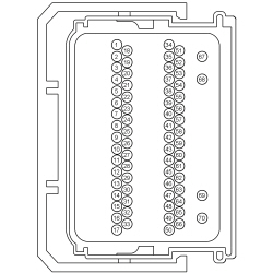
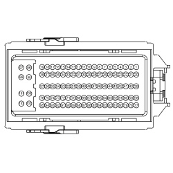
- Disconnect: PCM C175B (3.5L
) or C1381B (3.5L
).
- Ignition ON.
- For the 3.5L
, measure the
voltage
between:
| Positive
| Lead
| Negative
| Lead
| | Pin
| Circuit
| Pin
| Circuit
| | C175B-13
| CCB08 (VT/WH)
| —
| Ground
|
 - For the 3.5L
, measure the
voltage
between:
| Positive
| Lead
| Negative
| Lead
| | Pin
| Circuit
| Pin
| Circuit
| | C1381B-66
| CCB08 (VT/WH)
| —
| Ground
|
 - Is the voltage greater than 11 volts?
| Yes
GO to
B8
.
No
REPAIR the circuit for an open.
|
|
B4 CHECK THE CRUISE CONTROL DEACTIVATOR SWITCH FOR CORRECT OPERATION
|
|
- Ignition OFF.
- Disconnect: PCM C175B (3.5L
) or C1381B (3.5L
).
- For the 3.5L
, measure the
resistance
between:
| Positive
| Lead
| Negative
| Lead
| | Pin
| Circuit
| Pin
| Circuit
| | C175B-46
| CES09 (VT/OG)
| —
| Ground
|
 - For the 3.5L
, measure the
resistance
between:
| Positive
| Lead
| Negative
| Lead
| | Pin
| Circuit
| Pin
| Circuit
| | C1381B-65
| CES09 (VT/OG)
| —
| Ground
|
 - Is the resistance less than 3 ohms with the brake pedal released, and greater than 10,000 ohms with the brake pedal firmly applied?
| Yes
GO to
B8
.
No
GO to
B5
.
|
|
B5 CHECK THE CRUISE CONTROL DEACTIVATOR SWITCH GROUND CIRCUIT FOR AN OPEN
|
|
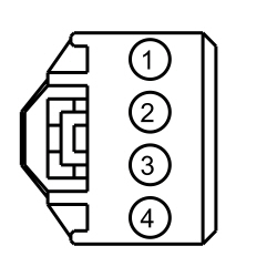
- Disconnect: Brake Pedal Position Switch C278.
- Measure the
resistance
between:
| Positive
| Lead
| Negative
| Lead
| | Pin
| Circuit
| Pin
| Circuit
| | C278-3
| GD113 (BK/YE)
| —
| Ground
|
 - Is the resistance less than 3 ohms?
| Yes
GO to
B6
.
No
REPAIR the circuit for an open.
|
|
B6 CHECK THE CRUISE CONTROL DEACTIVATOR SWITCH SIGNAL CIRCUIT FOR A SHORT TO GROUND
|
|
- Measure the
resistance
between:
| Positive
| Lead
| Negative
| Lead
| | Pin
| Circuit
| Pin
| Circuit
| | C278-2
| CES09 (VT/OG)
| —
| Ground
|
 - Is the resistance less than 3 ohms?
| Yes
GO to
B7
.
No
REPAIR the circuit for an open.
|
|
B7 CHECK THE CRUISE CONTROL DEACTIVATOR SWITCH SIGNAL CIRCUIT FOR AN OPEN
|
|
- Connect a
fused jumper wire
between:
| Positive
| Lead
| Negative
| Lead
| | Pin
| Circuit
| Pin
| Circuit
| | C278-2
| CES09 (VT/OG)
| C278-3
| GD113 (BK/YE)
|
 - For the 3.5L
, measure the
resistance
between:
| Positive
| Lead
| Negative
| Lead
| | Pin
| Circuit
| Pin
| Circuit
| | C175B-46
| CES09 (VT/OG)
| —
| Ground
|
 - For the 3.5L
, measure the
resistance
between:
| Positive
| Lead
| Negative
| Lead
| | Pin
| Circuit
| Pin
| Circuit
| | C1381B-65
| CES09 (VT/OG)
| —
| Ground
|
 - Is the resistance less than 3 ohms?
| Yes
INSTALL a new stoplamp switch. REFER to
Section 417-01
.
No
REPAIR circuit CES09 (VT/OG) for an open.
|
|
B8 CHECK FOR CORRECT PCM OPERATION
|
|
- Disconnect and inspect all the PCM connectors.
- Repair:
- corrosion (install new connector or terminals - clean module pins)
- damaged pins - install new terminals/pins
- pushed-out pins - install new pins as necessary
- Reconnect the PCM connectors. Make sure they seat and latch correctly.
- Operate the system and determine if the concern is still present.
- Is the concern still present?
| Yes
CHECK
for any applicable TSBs. If a TSB exists for this concern, DISCONTINUE this test and FOLLOW TSB instructions. If no TSBs address this concern, INSTALL a new PCM. REFER to
Section 303-14
.
No
The system is operating correctly at this time. The concern may have been caused by module connections. ADDRESS the root cause of any connector or pin issues.
|
Pinpoint Test C: The Cruise Control Switch Is Inoperative/Does Not Operate Correctly
Diagnostic Overview
Diagnostics in this manual assume a certain skill level and knowledge of Ford-specific diagnostic practices. Refer to Diagnostic Methods in
Section 100-00
for information about these practices.
Refer to Wiring Diagrams Cell
31
, Speed Control for schematic and connector information.
Normal Operation and Fault Conditions
Refer to Steering Wheel Switch Function in
Cruise Control
.
DTC Fault Trigger Conditions
| DTC
| Description
| Fault Trigger Conditions
|
|---|
| B137F:09
| Steering Wheel Left Switch Pack: Component Failure
| A continuous and on-demand DTC that sets when one or more of the cruise control switches are stuck.
|
| B137F:11
| Steering Wheel Left Switch Pack: Circuit Short To Ground
| A continuous and on-demand DTC that sets when the cruise control switch circuits are shorted to ground.
|
| B137F:17
| Steering Wheel Left Switch Pack: Circuit Voltage Above Threshold
| A continuous and on-demand DTC that sets when the cruise control switch circuits are shorted to voltage.
|
Possible Sources
- Wiring, terminals and connectors
- Cruise control switches (part of the message center switch)
- Clockspring
PINPOINT TEST C: THE CRUISE CONTROL SWITCH IS INOPERATIVE/DOES NOT OPERATE CORRECTLY
NOTICE:
Use the correct probe adapter(s) when making measurements. Failure to use the correct probe adapter(s) may damage the connector.
| Test Step
| Result / Action to Take
|
|---|
|
C1 CHECK THE CRUISE CONTROL SWITCH
|
|
- Ignition ON.
- Enter the following diagnostic mode on the scan tool:
DataLogger.
- Press each cruise control switch while monitoring the cruise control switch PID (SCCS).
Cruise Control Switches
| Cruise Control Switch
| SCCS PID Value
|
|---|
| —
| None Pressed
| | RES
| RESUME
| | CNCL
| CANCEL
| | ON/OFF (pressed up)
| On
| | ON/OFF (pressed down)
| Off
| | SET (pressed up)
| SET/+
| | SET (pressed down)
| SET/-
|
- Does the PID value agree with the switch position?
| Yes
GO to
C5
.
No
If only one switch value does not display the correct PID value, INSTALL a new LH steering wheel switch. REFER to
Section 211-05
.
Otherwise, GO to
C2
.
|
|
C2 CHECK FOR VOLTAGE TO THE CRUISE CONTROL SWITCHES
|
|
- Ignition OFF.
- Remove the driver air bag module. Refer to
Section 501-20B
.
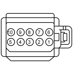
- Disconnect: LH Steering Wheel Controls C2998.
- Ignition ON.
- Measure the
voltage
between:
| Positive
| Lead
| Negative
| Lead
| | Pin
| Circuit
| Pin
| Circuit
| | C2998-4
| —
| C2998-1
| —
| | C2998-6
| —
| C2998-1
| —
| | C2998-8
| —
| C2998-1
| —
|
 - Is the voltage approximately 5 volts?
| Yes
INSTALL a new LH steering wheel switch. REFER to
Section 211-05
.
No
GO to
C3
.
|
|
C3 CHECK FOR VOLTAGE TO THE CLOCKSPRING
|
|
- Ignition OFF.
- Disconnect: Clockspring C218B.
- Ignition ON.
- Measure the
component side voltage
between:
| Positive
| Lead
| Negative
| Lead
| | Pin
| Circuit
| Pin
| Circuit
| | C218B, pin 6
| —
| C218B, pin 8
| —
| | C218B, pin 7
| —
| C218B, pin 8
| —
| | C218B, pin 15
| —
| C218B, pin 8
| —
|
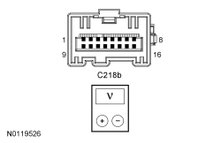 - Is the voltage approximately 5 volts?
| Yes
INSTALL a new steering wheel. REFER to
Section 211-04
. INSTALL the driver air bag module. REFER to
Section 501-20B
.
No
GO to
C4
.
|
|
C4 CHECK FOR VOLTAGE AT THE
|
|
- Ignition OFF.
- Remove the clockspring. Refer to
Section 501-20B
.
- Ignition ON.
- Measure the
component side voltage
between:
| Positive
| Lead
| Negative
| Lead
| | Pin
| Circuit
| Pin
| Circuit
| | C2414D, pin 5
| —
| C2414D, pin 9
| —
| | C2414D, pin 7
| —
| C2414D, pin 9
| —
| | C2414D, pin 8
| —
| C2414D, pin 9
| —
|
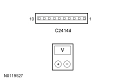 - Is the voltage approximately 5 volts?
| Yes
INSTALL a new clockspring. REFER to
Section 501-20B
.
No
GO to
C5
.
|
|
C5 CHECK FOR CORRECT
OPERATION
|
|
- Disconnect and inspect all the
connectors.
- Repair:
- corrosion (install new connector or terminals - clean module pins)
- damaged pins - install new terminals/pins
- pushed-out pins - install new pins as necessary
- Reconnect the
connectors. Make sure they seat and latch correctly.
- Operate the system and determine if the concern is still present.
- Is the concern still present?
| Yes
CHECK
for any applicable TSBs. If a TSB exists for this concern, DISCONTINUE this test and FOLLOW TSB instructions. If no TSBs address this concern, INSTALL a new
. REFER to
Section 211-05
.
No
The system is operating correctly at this time. The concern may have been caused by module connections. ADDRESS the root cause of any connector or pin issues.
|
Pinpoint Test D: DTC U0129
Diagnostic Overview
Diagnostics in this manual assume a certain skill level and knowledge of Ford-specific diagnostic practices. Refer to Diagnostic Methods in
Section 100-00
for information about these practices.
DTC Fault Trigger Conditions
| DTC
| Description
| Fault Trigger Conditions
|
|---|
| U0129
| Lost Communication With Brake System Control Module
| Sets in the PCM if data messages received from the ABS module over the
are missing.
|
Possible Sources
- PCM
- ABS module
PINPOINT TEST D: DTC U0129
| Test Step
| Result / Action to Take
|
|---|
|
D1 VERIFY THE CUSTOMER CONCERN
|
|
- Ignition ON.
- Verify there is an observable symptom present.
- Is an observable symptom present?
| Yes
GO to
D2
.
No
The system is operating normally at this time. The DTC may have been set due to high network traffic or an intermittent fault condition.
|
|
D2 CHECK THE COMMUNICATION NETWORK
|
|
- Ignition ON.
- Using a scan tool, perform the network test.
- Does the ABS module pass the network test?
| Yes
GO to
D3
.
No
REFER to
Section 418-00
, The ABS Module Does Not Respond To The Scan Tool.
|
|
D3 RETRIEVE THE RECORDED DTCs FROM THE PCM AND ABS MODULE SELF-TESTS
|
|
- Using a scan tool, perform self-test on the:
- Are any low or high voltage DTCs recorded?
| Yes
REFER to
Section 419-10
.
No
GO to
D4
.
|
|
D4 CHECK FOR DTC U0129 SET IN OTHER MODULES
|
|
- Using a scan tool, clear all DTCs.
- Ignition OFF.
- Ignition ON.
- Wait 10 seconds.
- Using a scan tool, retrieve all continuous memory DTCs.
- Does DTC U0129 set in the PCM?
| Yes
INSTALL a new ABS module. REFER to
Section 206-09
.
No
INSTALL a new PCM. REFER to
Section 303-14
.
|
Pinpoint Test E: DTC P193D
Diagnostic Overview
Diagnostics in this manual assume a certain skill level and knowledge of Ford-specific diagnostic practices. Refer to Diagnostic Methods in
Section 100-00
for information about these practices.
DTC Fault Trigger Conditions
| DTC
| Description
| Fault Trigger Conditions
|
|---|
| P193D
| Cruise Control Multi-Function Input Signal
| Sets when the PCM is not receiving the
signal from the
for the cruise control switches.
|
Possible Sources
- Cruise control switches (part of the message center switch)
- PCM
PINPOINT TEST E: DTC P193D
| Test Step
| Result / Action to Take
|
|---|
|
E1 CHECK THE CRUISE CONTROL SWITCH PID IN THE PCM
|
|
- Ignition ON.
- Enter the following diagnostic mode on the scan tool: Powertrain DataLogger — Cruise Control.
- Press each cruise control switch while monitoring the cruise control switch PID (SCCS).
Cruise Control Switches
| Cruise Control Switch
| SCCS PID Value
|
|---|
| —
| None Pressed
| | RES
| RESUME
| | CNCL
| CANCEL
| | ON/OFF (pressed up)
| On
| | ON/OFF (pressed down)
| Off
| | SET (pressed up)
| SET/+
| | SET (pressed down)
| SET/-
|
- Does the PID value agree with the switch position?
| Yes
GO to
E2
.
No
GO to Pinpoint Test C
.
|
|
E2 CHECK THE COMMUNICATION NETWORK
|
|
- Ignition ON.
- Using a scan tool, perform the network test.
- Does the
module pass the network test?
| Yes
GO to
E3
.
No
REFER to
Section 418-00
, The
Does Not Respond To The Scan Tool.
|
|
E3 RECHECK THE PCM DTCs
|
|
NOTE:
If new modules were installed prior to the DTC being set, the module configuration may be incorrectly set during the
or the
may not have been carried out.
- Using a scan tool, clear the DTCs. Repeat the PCM self-test.
- Is DTC P193D still present?
| Yes
GO to
E4
.
No
The system is operating correctly at this time. The DTC may have been set due to high network traffic or an intermittent fault condition.
|
|
E4 CHECK FOR CORRECT PCM OPERATION
|
|
- Disconnect and inspect all the PCM connectors.
- Repair:
- corrosion (install new connector or terminals - clean module pins)
- damaged pins - install new terminals/pins
- pushed-out pins - install new pins as necessary
- Reconnect the PCM connectors. Make sure they seat and latch correctly.
- Operate the system and determine if the concern is still present.
- Is the concern still present?
| Yes
CHECK
for any applicable TSBs. If a TSB exists for this concern, DISCONTINUE this test and FOLLOW TSB instructions. If no TSBs address this concern, INSTALL a new PCM. REFER to
Section 303-14
.
No
The system is operating correctly at this time. The concern may have been caused by module connections. ADDRESS the root cause of any connector or pin issues.
|


