SECTION 419-03B: Cruise Control — Adaptive
| 2014 Flex Workshop Manual
|
DIAGNOSIS AND TESTING
| Procedure revision date: 05/02/2013
|
Cruise Control
DTC Charts
Diagnostics in this manual assume a certain skill level and knowledge of Ford-specific diagnostic practices. Refer to Diagnostic Methods in
Section 100-00
for information about these practices.
PCM DTC Chart
DTC Chart
Cruise-Control Module (C-CM) DTC Chart
| DTC
| Description
| Action
|
|---|
| C0072:00
| Brake Temperature Too High: No Sub Type Information
| REFER to
Section 206-09
to continue diagnosis of the ABS system.
|
| C1132:4B
| Head Up Display: Over Temperature
| REFER to
Section 419-03C
.
|
| C1A67:54
| Forward Looking Sensor: Missing Calibration
| GO to Pinpoint Test E
.
|
| C1A67:76
| Forward Looking Sensor: Wrong Mounting Position
| GO to Pinpoint Test E
.
|
| C1A67:96
| Forward Looking Sensor: Component Internal Failure
| GO to Pinpoint Test D
.
|
| C1A67:97
| Forward Looking Sensor: Component or System Operation Obstructed or Blocked
| GO to Pinpoint Test F
.
|
| C1A67:98
| Forward Looking Sensor: Component or System Over Temperature
| The Cruise-Control Module (C-CM) was over-temperature. This may occur during extended use or extremely high weather temperatures. The adaptive cruise control system operation resumes after the
cools.
|
| U0001:88
| High Speed CAN Communication Bus: Bus Off
| REFER to
Section 418-00
.
|
| U0100:00
| Lost Communication With ECM/PCM "A": No Sub Type Information
| GO to Pinpoint Test G
.
|
| U0121:00
| Lost Communication With Anti-Lock Brake System (ABS) Control Module: No Sub Type Information
| GO to Pinpoint Test H
.
|
| U0140:00
| Lost Communication With Body Control Module: No Sub Type Information
| GO to Pinpoint Test S
.
|
| U0151:87
| Lost Communication With Restraints Control Module: Missing Message
| GO to Pinpoint Test I
.
|
| U0155:00
| Lost Communication With Instrument Panel Cluster (IPC) Control Module: No Sub Type Information
| GO to Pinpoint Test J
.
|
| U0158:00
| Lost Communication With Head Up Display: No Sub Type Information
| GO to Pinpoint Test K
.
|
| U0212:00
| Lost Communication With Steering Column Control Module: No Sub Type Information
| GO to Pinpoint Test L
.
|
| U0300:55
| Internal Control Module Software Incompatibility: Not Configured
| GO to Pinpoint Test N
.
|
| U0401:68
| Invalid Data Received from ECM/PCM A: Event Information
| This DTC sets when the
receives invalid network data from the PCM with a faulted Vehicle Speed Sensor (VSS) signal, Accelerator Pedal Position (APP) signal or cruise control switch input. RETRIEVE and REPAIR all non-network DTCs in the other modules on the network.
|
| U0418:68
| Invalid Data Received From Brake System Control Module: Event Information
| This DTC sets when the
receives invalid network data from the ABS module with a faulted brake signal input, yaw rate input, steering wheel angle input or vehicle speed input. RETRIEVE and REPAIR all non-network DTCs in the other modules on the network.
|
| U0424:68
| Invalid Data Received From HVAC Control Module: Event Information
| This DTC sets when the
receives invalid network data from the HVAC module with a faulted sunload sensor input. RETRIEVE and REPAIR all non-network DTCs in the other modules on the network.
|
| U0429:68
| Invalid Data Received From Steering Column Control Module: Event Information
| This DTC sets when the
receives invalid network data from the Steering Column Control Module (SCCM) with a faulted cruise control switch input. RETRIEVE and REPAIR all non-network DTCs in the other modules on the network.
|
| U0452:86
| Invalid Data Received From Restraints Control Module: Signal Invalid
| This DTC sets when the
receives invalid network data from the
with a faulted yaw rate input. RETRIEVE and REPAIR all non-network DTCs in the other modules on the network. CHECK the vehicle service history for recent service actions related to this module. This DTC sets due to incomplete or incorrect
procedures. If there have been recent service actions with this module, REPEAT the
procedure as directed by the scan tool (REFER to
Section 418-01
for further information). If there have been no recent service actions, INSTALL a new module to correct the failure to retain configuration data. REFER to
Cruise-Control Module (C-CM)
.
|
| U0459:68
| Invalid Data Received From Head Up Display: Event Information
| GO to Pinpoint Test T
.
|
| U2100:00
| Initial Configuration Not Complete: No Sub Type Information
| This DTC sets when either the
detects that the
is not configured correctly or the
configuration has not been completed. DETERMINE which module (
or
) has been replaced. CARRY OUT the Programmable Module Installation (PMI) (when the original module is not available) for the module in question. REFER to
Section 418-01
.
|
| U2101:00
| Control Module Configuration Incompatible: No Sub Type Information
| This DTC sets when the
detects the
is not transmitting the correct configuration information. The
needs to be configured. CARRY OUT the
(when the original module is not available). REFER to
Section 418-01
.
|
| U3000:41
| Control Module: General Checksum Failure
| If DTC U3000:41 is retrieved again, INSTALL a new
. REFER to
Cruise-Control Module (C-CM)
.
|
| U3000:42
| Control Module: General Memory Failure
| CLEAR the DTCs. RETEST the adaptive cruise control system. REPEAT the self-test. If DTC U3000:42 is retrieved again, INSTALL a new
. REFER to
Cruise-Control Module (C-CM)
.
|
| U3000:44
| Control Module: Data Memory Failure
| CLEAR the DTCs. RETEST the adaptive cruise control system. REPEAT the self-test. If DTC U3000:44 is retrieved again, INSTALL a new
. REFER to
Cruise-Control Module (C-CM)
.
|
| U3000:49
| Control Module: Internal Electronic Failure
| If DTC U3000:49 is retrieved again, INSTALL a new
. REFER to
Cruise-Control Module (C-CM)
.
|
| U3000:63
| Control Module: Circuit/Component Protection Time-Out
| GO to Pinpoint Test O
.
|
| U3000:66
| Control Module: Signal Has Too Many Transitions/Events
| GO to Pinpoint Test P
.
|
| U3003:16
| Battery Voltage: Circuit Voltage Below Threshold
| GO to Pinpoint Test Q
.
|
| U3003:17
| Battery Voltage: Circuit Voltage Above Threshold
| GO to Pinpoint Test R
.
|
ABS Module DTC Chart
| DTC
| Description
| Action
|
|---|
| U0405:83
| Invalid Data Received From Cruise Control Module: Value of Signal Protection Calculation Incorrect
| This DTC sets when the ABS module receives invalid network data from the Cruise-Control Module (C-CM). RETRIEVE and REPAIR all non-network DTCs in the
and other modules on the network.
|
| U2101:00
| Control Module Configuration Incompatible: No Sub Type Information
| This DTC sets when the ABS module receives adaptive cruise control and forward collision warning data when the ABS module is not configured for adaptive cruise control and forward collision warning in the ABS module.
CARRY OUT the Programmable Module Installation (PMI) procedures for the ABS module. REFER to
Section 418-01
. TEST the system for normal operation.
|
| U2107:00
| Collision Mitigation By Braking: No Sub Type Information
| This DTC sets in the ABS module due to long and too often collision mitigation brake request from the
.
RETRIEVE and REPAIR all non-network DTCs in the
and other modules on the network.
|
| U2108:62
| Adaptive Cruise Control: Signal Compare Failure
| This DTC sets in the ABS module due to an internal comparison of the output braking applied is greater than the
brake request. RETRIEVE and REPAIR all DTCs in the ABS module. REFER to
Section 206-09
.
|
| All other DTCs
| —
| REFER to
Section 206-09
.
|
DTC Chart
| DTC
| Description
| Action
|
|---|
| U0405:68
| Invalid Data Received From Cruise Control Module: No Sub Type Information
| This DTC sets when the Body Control Module (BCM) receives invalid network data from the Cruise-Control Module (C-CM). RETRIEVE and REPAIR all non-network DTCs in the
and other modules on the network.
|
| U0433:00
| Invalid Data Received From Cruise Control Front Distance Range Sensor: No Sub Type Information
| This DTC sets when the
receives invalid network data from the
radar sensor that is integral to the
. RETRIEVE and REPAIR all non-network DTCs in the
and other modules on the network.
|
| U2107:53
| Collision Mitigation By Braking: Deactivated
| The
uses an internal fault detection incremental counter to record the amount of faults from the
. Once the incremental counter has reached 128 faults, DTC U2107:53 sets in the
.
RETRIEVE and REPAIR all non-network DTCs in the
and other modules on the network.
|
| U2108:53
| Adaptive Cruise Control: Deactivated
| The
uses an internal fault detection incremental counter to record the amount of faults from the
. Once the incremental counter has reached 128 faults, DTC U2108:53 sets in the
.
RETRIEVE and REPAIR all non-network DTCs in the
and other modules on the network.
|
| All other DTCs
| —
| REFER to
Section 419-10
.
|
Symptom Chart
Diagnostics in this manual assume a certain skill level and knowledge of Ford-specific diagnostic practices. Refer to Diagnostic Methods in
Section 100-00
for information about these practices.
Symptom Chart
| Condition
| Possible Sources
| Action
|
|---|
- The cruise control is inoperative
| - Refer to the Diagnostic Routine
| |
- The cruise control indicator lamp is never/always on
| - Wiring, terminals and connectors
- PCM
| |
- The cruise control switch is inoperative/does not operate correctly
| - Refer to the Diagnostic Routine
| |
- The adaptive cruise control does not function in rain or snow conditions
| - Refer to the Diagnostic Routine
| |
- "ADAPTIVE CRUISE NOT AVAILABLE SENSOR BLOCKED" message in the
message center
| - Refer to the Diagnostic Routine
| |
- The adaptive cruise control indicator lamp is never/always on
| - Wiring, terminals and connectors
- PCM
| |
- Unexpected adaptive cruise control braking
| | - The adaptive cruise control system can occasionally detect and respond to out-of-path vehicles, especially on curves, entry/exit ramps or when changing lanes. CHECK the
and front bumper cover for damage. RETEST the adaptive cruise control system.
|
- Lack of adaptive cruise control braking
| | - The adaptive cruise control system may not detect and respond to vehicles carrying out close cut-ins or on tight curves (especially for vehicles on the passenger side) due to limited
field of view. CHECK the
and front bumper cover for damage. If no damage is observed, RETEST the adaptive cruise control system.
|
- Noise during adaptive cruise control braking
| | - The driver can detect some noise at low speeds when adaptive cruise control braking occurs. If braking noise continues, REFER to
Section 206-00
to continue diagnosis of the ABS system.
|
- The cruise control cannot set above 105 kmh (65 mph), 113 kmh (70 mph), 121 kmh (75 mph), or 129 kmh (80 mph)
| - A MyKey® restricted key is in use and MyKey® maximum speed limiter is turned on
| - VERIFY if a MyKey® restricted key is in use. REFER to
Section 419-01B
. With an admin key, VERIFY if MyKey® maximum speed limiter is turned on. REFER to the Owner's Literature. If necessary, VERIFY cruise control normal operation with an admin key.
|
Pinpoint Tests
Pinpoint Test A: The Cruise Control Is Inoperative
Diagnostic Overview
Diagnostics in this manual assume a certain skill level and knowledge of Ford-specific diagnostic practices. Refer to Diagnostic Methods in
Section 100-00
for information about these practices.
Normal Operation and Fault Conditions
Refer to Adaptive Cruise Control Operation in
Cruise Control
.
Refer to Steering Wheel Switch Function in
Cruise Control
.
Refer to Steering Wheel Switches in
Section 211-05
.
Possible Sources
- Wiring, terminals and connectors
- Cruise control switches (part of the message center switch)
- Cruise control deactivator switch (integral to the brake pedal position switch)
- Digital
sensor
- Brake pedal position switch
- Vehicle speed signal
- ABS module
- PCM
PINPOINT TEST A: THE CRUISE CONTROL IS INOPERATIVE
| Test Step
| Result / Action to Take
|
|---|
|
A1 CHECK FOR PCM DTCs
|
|
- Using a scan tool, perform the PCM
self-test.
- Are any DTCs recorded?
| Yes
REFER to DTC Charts in this section.
No
GO to
A2
.
|
|
A2 CHECK FOR
DTCs
|
|
- Using a scan tool, perform a
self-test.
- Are any DTCs recorded?
| Yes
REFER to DTC Charts in this section.
No
GO to
A3
.
|
|
A3 CHECK THE
DTCs
|
|
- Using a scan tool, perform a
self-test.
- Are any
DTCs recorded?
| Yes
REFER to DTC Charts in this section.
No
GO to
A4
.
|
|
A4 CHECK FOR LOST COMMUNICATION DTCs
|
|
- Ignition ON.
- Clear continuous DTCs from all modules.
- Ignition OFF.
- Ignition ON.
- Wait at least 10 seconds.
- Retrieve all continuous DTCs from all modules.
- Are any lost communication DTCs set in the
module?
| Yes
REFER to DTC Charts in this section.
No
GO to
A5
.
|
|
A5 CHECK FOR ABS MODULE DTCs
|
|
- Using a scan tool, perform an ABS module self-test.
- Are any DTCs recorded?
| Yes
REFER to DTC Charts in this section.
No
GO to
A6
.
|
|
A6 CHECK FOR
DTCs
|
|
- Using a scan tool, perform a
self-test.
- Are any DTCs recorded?
| Yes
REFER to DTC Charts in this section.
No
GO to
A7
.
|
|
A7 CHECK THE BRAKE PEDAL POSITION SWITCH (BOO1) AND CRUISE CONTROL DEACTIVATOR SWITCH (BOO2) PIDs
|
|
- Enter the following diagnostic mode on the scan tool: Powertrain DataLogger — Cruise Control.
- Monitor the powertrain PIDs BOO1 (brake pedal position switch) and BOO2 (cruise control deactivator switch) while applying and releasing the brake pedal as follows:
| Brake Pedal Position
| BOO1 PID
| BOO2 PID
|
|---|
| Released
| Off
| Off
| | Applied
| On
| On
|
- Do the PID values agree with the brake pedal position?
| Yes
GO to
A8
.
No
GO to Pinpoint Test B
.
|
|
A8 CHECK THE CRUISE CONTROL SWITCH
|
|
- Enter the following diagnostic mode on the scan tool: Powertrain DataLogger — Cruise Control.
- Press each cruise control switch while monitoring the cruise control switch PID (SCCS).
Cruise Control Switches
| Cruise Control Switch
| SCCS PID Value
|
|---|
| —
| None Pressed
| | RES/CNCL
| RESUME/CANCEL
| | ON/OFF
| On/Off
| | SET (pressed up)
| SET/+
| | SET (pressed down)
| SET/-
| | GAP (pressed up)
| GAP-
| | GAP (pressed down)
| GAP+
|
- Does the PID value agree with the switch position?
| Yes
GO to
A9
.
No
If only one switch does not display the correct PID value, INSTALL a new LH steering wheel switch. REFER to
Section 211-05
.
Otherwise,
GO to Pinpoint Test C
.
|
|
A9 MONITOR THE PCM
PID
|
|
- Enter the following diagnostic mode on the scan tool: PCM DataLogger.
- Monitor the PCM PID (TR).
- Select DRIVE.
- Does the PID value agree with the
selector lever position?
| Yes
GO to
A10
.
No
REFER to
Section 307-01
to continue diagnosis of the digital
sensor.
|
|
A10 CHECK FOR CORRECT PCM OPERATION
|
|
- Disconnect and inspect all the PCM connectors.
- Repair:
- corrosion (install new connector or terminals - clean module pins)
- damaged pins - install new terminals/pins
- pushed-out pins - install new pins as necessary
- Reconnect the PCM connectors. Make sure they seat and latch correctly.
- Operate the system and determine if the concern is still present.
- Is the concern still present?
| Yes
CHECK
for any applicable TSBs. If a TSB exists for this concern, DISCONTINUE this test and FOLLOW TSB instructions. If no TSBs address this concern, INSTALL a new PCM. REFER to
Section 303-14
.
No
The system is operating correctly at this time. The concern may have been caused by module connections. ADDRESS the root cause of any connector or pin issues.
|
Pinpoint Test B: DTC P0504, P0572, P0573 Or P1703
Diagnostic Overview
Diagnostics in this manual assume a certain skill level and knowledge of Ford-specific diagnostic practices. Refer to Diagnostic Methods in
Section 100-00
for information about these practices.
Refer to Wiring Diagrams Cell
31
, Speed Control for schematic and connector information.
Normal Operation and Fault Conditions
Refer to Brake Switch in
Cruise Control
.
DTC Fault Trigger Conditions
| DTC
| Description
| Fault Trigger Conditions
|
|---|
| P0504
| Brake Switch A / B Correlation
| A DTC that sets when the PCM does not sense the correct sequence of the brake pedal input signal from both the cruise control deactivator and brake pedal position switches when the brake pedal is pressed and released.
|
| P0572
| Brake Switch A Circuit Low
| A DTC that sets when the PCM detects an open in the brake pedal position switch signal. The PCM monitors the vehicle speed, the engine speed, the engine torque and the stoplamp input during start and stop driving cycles. If the brake pedal position switch input to the PCM is always off during start and stop driving cycles, this DTC sets in continuous memory.
|
| P0573
| Brake Switch A Circuit High
| A DTC that sets when the PCM detects a short to voltage on the brake pedal position switch signal. The PCM monitors the vehicle speed, the engine speed, the engine torque and the brake pedal position switch input during start and stop driving cycles. If the stoplamp lamp switch input to the PCM is always on during start and stop driving cycles, this DTC sets in continuous memory.
|
| P1703
| Brake Switch A / B Correlation
| A DTC that sets in the PCM during the self-test, when the brake pedal position switch input signal is high or does not cycle high and low.
|
Possible Sources
- Wiring, terminals and connectors
- Brake pedal position switch
- PCM
PINPOINT TEST B: DTC P0504, P0572, P0573 OR P1703
NOTICE:
Use the correct probe adapter(s) when making measurements. Failure to use the correct probe adapter(s) may damage the connector.
| Test Step
| Result / Action to Take
|
|---|
|
B1 CHECK THE OPERATION OF THE STOPLAMPS
|
|
- Ignition ON.
- Operate the stoplamps.
- Do the stoplamps and high mounted stoplamp operate correctly?
| Yes
GO to
B2
.
No
REFER to
Section 417-01
.
|
|
B2 CHECK THE BRAKE PEDAL POSITION SWITCH (BOO1) AND CRUISE CONTROL DEACTIVATOR SWITCH (BOO2) PIDs
|
|
- Enter the following diagnostic mode on the scan tool: Powertrain DataLogger — Cruise Control.
- Monitor the powertrain PIDs BOO1 (brake pedal position switch) and BOO2 (cruise control deactivator switch) while applying and releasing the brake pedal as follows:
| Brake Pedal Position
| BOO1 PID
| BOO2 PID
|
|---|
| Released
| Off
| Off
| | Applied
| On
| On
|
- Do the PID values agree with the brake pedal position?
| Yes
GO to
B8
.
No
For an incorrect BOO1 PID value, GO to
B3
.
For an incorrect BOO2 PID value, GO to
B4
.
|
|
B3 CHECK THE BRAKE PEDAL POSITION SWITCH CIRCUIT
|
|
- Ignition OFF.
- Disconnect: PCM C175B (3.5L
) or C1381B (3.5L
).
- Ignition ON.
- For the 3.5L
, measure the
voltage
between:
| Positive
| Lead
| Negative
| Lead
| | Pin
| Circuit
| Pin
| Circuit
| | C175B-13
| CCB08 (VT/WH)
| —
| Ground
|
 - For the 3.5L
, measure the
voltage
between:
| Positive
| Lead
| Negative
| Lead
| | Pin
| Circuit
| Pin
| Circuit
| | C1381B-66
| CCB08 (VT/WH)
| —
| Ground
|
 - Is the voltage greater than 11 volts?
| Yes
GO to
B8
.
No
REPAIR the circuit for an open.
|
|
B4 CHECK THE CRUISE CONTROL DEACTIVATOR SWITCH FOR CORRECT OPERATION
|
|
- Ignition OFF.
- Disconnect: PCM C175B (3.5L
) or C1381B (3.5L
).
- For the 3.5L
, measure the
resistance
between:
| Positive
| Lead
| Negative
| Lead
| | Pin
| Circuit
| Pin
| Circuit
| | C175B-46
| CES09 (VT/OG)
| —
| Ground
|
- For the 3.5L
, measure the
resistance
between:
| Positive
| Lead
| Negative
| Lead
| | Pin
| Circuit
| Pin
| Circuit
| | C1381B-65
| CES09 (VT/OG)
| —
| Ground
|
- Is the resistance less than 3 ohms with the brake pedal released, and greater than 10,000 ohms with the brake pedal firmly applied?
| Yes
GO to
B8
.
No
GO to
B5
.
|
|
B5 CHECK THE CRUISE CONTROL DEACTIVATOR SWITCH GROUND CIRCUIT FOR AN OPEN
|
|
- Disconnect: Brake Pedal Position Switch C278.
- Measure the
resistance
between:
| Positive
| Lead
| Negative
| Lead
| | Pin
| Circuit
| Pin
| Circuit
| | C278-3
| GD113 (BK/YE)
| —
| Ground
|
 - Is the resistance less than 3 ohms?
| Yes
GO to
B6
.
No
REPAIR the circuit for an open.
|
|
B6 CHECK THE CRUISE CONTROL DEACTIVATOR SWITCH SIGNAL CIRCUIT FOR A SHORT TO GROUND
|
|
- Measure the
resistance
between:
| Positive
| Lead
| Negative
| Lead
| | Pin
| Circuit
| Pin
| Circuit
| | C278-2
| CES09 (VT/OG)
| —
| Ground
|
- Is the resistance less than 3 ohms?
| Yes
GO to
B7
.
No
REPAIR the circuit for an open.
|
|
B7 CHECK THE CRUISE CONTROL DEACTIVATOR SWITCH SIGNAL CIRCUIT FOR AN OPEN
|
|
- Connect a
fused jumper wire
between:
| Lead 1
| Lead 2
| | Pin
| Circuit
| Pin
| Circuit
| | C278-2
| CES09 (VT/OG)
| C278-3
| GD113 (BK/YE)
|
- For the 3.5L
, measure the
resistance
between:
| Positive
| Lead
| Negative
| Lead
| | Pin
| Circuit
| Pin
| Circuit
| | C175B-46
| CES09 (VT/OG)
| —
| Ground
|
- For the 3.5L
, measure the
resistance
between:
| Positive
| Lead
| Negative
| Lead
| | Pin
| Circuit
| Pin
| Circuit
| | C1381B-65
| CES09 (VT/OG)
| —
| Ground
|
- Is the resistance less than 3 ohms?
| Yes
INSTALL a new brake pedal position switch. REFER to
Section 417-01
.
No
REPAIR the circuit.
|
|
B8 CHECK FOR CORRECT PCM OPERATION
|
|
- Disconnect and inspect all the PCM connectors.
- Repair:
- corrosion (install new connector or terminals - clean module pins)
- damaged pins - install new terminals/pins
- pushed-out pins - install new pins as necessary
- Reconnect the PCM connectors. Make sure they seat and latch correctly.
- Operate the system and determine if the concern is still present.
- Is the concern still present?
| Yes
CHECK
for any applicable TSBs. If a TSB exists for this concern, DISCONTINUE this test and FOLLOW TSB instructions. If no TSBs address this concern, INSTALL a new PCM. REFER to
Section 303-14
.
No
The system is operating correctly at this time. The concern may have been caused by module connections. ADDRESS the root cause of any connector or pin issues.
|
Pinpoint Test C: The Cruise Control Switch Is Inoperative/Does Not Operate Correctly
Diagnostic Overview
Diagnostics in this manual assume a certain skill level and knowledge of Ford-specific diagnostic practices. Refer to Diagnostic Methods in
Section 100-00
for information about these practices.
Refer to Wiring Diagrams Cell
31
, Speed Control for schematic and connector information.
Normal Operation and Fault Conditions
Refer to Steering Wheel Switch Function in
Cruise Control
.
DTC Fault Trigger Conditions
| DTC
| Description
| Fault Trigger Conditions
|
|---|
| B137F:09
| Steering Wheel Left Switch Pack: Component Failure
| A continuous and on-demand DTC that sets when one or more of the cruise control switches are stuck.
|
| B137F:11
| Steering Wheel Left Switch Pack: Circuit Short To Ground
| A continuous and on-demand DTC that sets when the cruise control switch circuits are shorted to ground.
|
| B137F:17
| Steering Wheel Left Switch Pack: Circuit Voltage Above Threshold
| A continuous and on-demand DTC that sets when the cruise control switch circuits voltage is greater than expected.
|
Possible Sources
- Wiring, terminals and connectors
- Cruise control switches (part of the message center switch)
- Clockspring
PINPOINT TEST C: THE CRUISE CONTROL SWITCH IS INOPERATIVE/DOES NOT OPERATE CORRECTLY
NOTICE:
Use the correct probe adapter(s) when making measurements. Failure to use the correct probe adapter(s) may damage the connector.
| Test Step
| Result / Action to Take
|
|---|
|
C1 CHECK THE CRUISE CONTROL SWITCH
|
|
- Ignition ON.
- Enter the following diagnostic mode on the scan tool:
DataLogger.
- Press each cruise control switch while monitoring the cruise control switch PID (SCCS).
Cruise Control Switches
| Cruise Control Switch
| SCCS PID Value
|
|---|
| —
| None Pressed
| | RES
| RESUME
| | CNCL
| CANCEL
| | ON/OFF (pressed up)
| On
| | ON/OFF (pressed down)
| Off
| | SET (pressed up)
| SET/+
| | SET (pressed down)
| SET/-
|
- Does the PID value agree with the switch position?
| Yes
GO to
C5
.
No
If only one switch value does not display the correct PID value, INSTALL a new LH steering wheel switch. REFER to
Section 211-05
.
Otherwise, GO to
C2
.
|
|
C2 CHECK FOR VOLTAGE TO THE CRUISE CONTROL SWITCHES
|
|
- Ignition OFF.
- Remove the driver air bag module. Refer to
Section 501-20B
.
- Disconnect: LH Steering Wheel Controls C2998.
- Ignition ON.
- Measure the
voltage
between:
| Positive
| Lead
| Negative
| Lead
| | Pin
| Circuit
| Pin
| Circuit
| | C2998-4
| —
| C2998-1
| —
| | C2998-6
| —
| C2998-1
| —
| | C2998-8
| —
| C2998-1
| —
|
 - Is the voltage approximately 5 volts?
| Yes
INSTALL a new LH steering wheel switch. REFER to
Section 211-05
.
No
GO to
C3
.
|
|
C3 CHECK FOR VOLTAGE TO THE CLOCKSPRING
|
|
- Ignition OFF.
- Disconnect: Clockspring C218B.
- Ignition ON.
- Measure the
component side voltage
between:
| Positive
| Lead
| Negative
| Lead
| | Pin
| Circuit
| Pin
| Circuit
| | C218B, pin 6
| —
| C218B, pin 8
| —
| | C218B, pin 7
| —
| C218B, pin 8
| —
| | C218B, pin 15
| —
| C218B, pin 8
| —
|
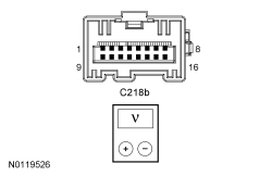 - Is the voltage approximately 5 volts?
| Yes
INSTALL a new steering wheel. REFER to
Section 211-04
. INSTALL the driver air bag module. REFER to
Section 501-20B
.
No
GO to
C4
.
|
|
C4 CHECK FOR VOLTAGE AT THE
|
|
- Ignition OFF.
- Remove the clockspring. Refer to
Section 501-20B
.
- Ignition ON.
- Measure the
component side voltage
between:
| Positive
| Lead
| Negative
| Lead
| | Pin
| Circuit
| Pin
| Circuit
| | C2414D, pin 5
| —
| C2414D, pin 9
| —
| | C2414D, pin 7
| —
| C2414D, pin 9
| —
| | C2414D, pin 8
| —
| C2414D, pin 9
| —
|
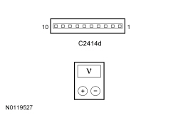 - Is the voltage approximately 5 volts?
| Yes
INSTALL a new clockspring. REFER to
Section 501-20B
.
No
GO to
C5
.
|
|
C5 CHECK FOR CORRECT
OPERATION
|
|
- Disconnect and inspect all the
connectors.
- Repair:
- corrosion (install new connector or terminals - clean module pins)
- damaged pins - install new terminals/pins
- pushed-out pins - install new pins as necessary
- Reconnect the
connectors. Make sure they seat and latch correctly.
- Operate the system and determine if the concern is still present.
- Is the concern still present?
| Yes
CHECK
for any applicable TSBs. If a TSB exists for this concern, DISCONTINUE this test and FOLLOW TSB instructions. If no TSBs address this concern, INSTALL a new
. REFER to
Section 211-05
.
No
The system is operating correctly at this time. The concern may have been caused by module connections. ADDRESS the root cause of any connector or pin issues.
|
Pinpoint Test D: DTC C1A67:96
Diagnostic Overview
Diagnostics in this manual assume a certain skill level and knowledge of Ford-specific diagnostic practices. Refer to Diagnostic Methods in
Section 100-00
for information about these practices.
Normal Operation and Fault Conditions
DTC Fault Trigger Conditions
| DTC
| Description
| Fault Trigger Conditions
|
|---|
| C1A67:96
| Forward Looking Sensor: Component Internal Failure
| Sets when the
detects an internal failure or invalid radar data with the radar sensor.
|
PINPOINT TEST D: DTC C1A67:96
| Test Step
| Result / Action to Take
|
|---|
|
D1 CHECK THE DTCs FROM BOTH THE CONTINUOUS AND ON-DEMAND
SELF-TESTS
|
|
- Ignition ON.
- Clear continuous DTCs from all modules.
- Ignition OFF.
- Ignition ON.
- Wait at least 10 seconds.
- Using a scan tool, perform the
self-test.
- Check the
DTCs from the continuous and on-demand self-tests.
- Is DTC C1A67:96 recorded?
| Yes
GO to
D2
.
No
The system is operating correctly at this time. The DTC may have been set due to an intermittent fault condition. CHECK the
connector and the
bus wire for corrosion.
|
|
D2 CHECK FOR CORRECT
OPERATION
|
|
- Disconnect and inspect the
connector.
- Repair:
- corrosion (install new connector or terminals - clean module pins)
- damaged pins - install new terminals/pins
- pushed-out pins - install new pins as necessary
- Reconnect the
connector. Make sure it seats and latches correctly.
- Operate the system and determine if the concern is still present.
- Is the concern still present?
| Yes
CHECK
for any applicable TSBs. If a TSB exists for this concern, DISCONTINUE this test and FOLLOW TSB instructions. If no TSBs address this concern, INSTALL a new
. REFER to
Cruise-Control Module (C-CM)
.
No
The system is operating correctly at this time. The concern may have been caused by module connections. ADDRESS the root cause of any connector or pin issues.
|
Pinpoint Test E: DTC C1A67:54 Or DTC C1A67:76
Diagnostic Overview
Diagnostics in this manual assume a certain skill level and knowledge of Ford-specific diagnostic practices. Refer to Diagnostic Methods in
Section 100-00
for information about these practices.
Normal Operation and Fault Conditions
DTC Fault Trigger Conditions
| DTC
| Description
| Fault Trigger Conditions
|
|---|
| C1A67:54
| Forward Looking Sensor: Missing Calibration
| Set by the
as a continuous memory and on-demand DTC if the
detects a misalignment of the radar due to the alignment angle being out of range.
|
| C1A67:76
| Forward Looking Sensor: Wrong Mounting Position
| Set by the
as a continuous memory and on-demand DTC if the
detects a misalignment of the radar due to the vertical alignment angle being out of range.
|
Possible Sources
- alignment
- mounting bracket
PINPOINT TEST E: DTC C1A67:54 OR DTC C1A67:76
| Test Step
| Result / Action to Take
|
|---|
|
E1 INSPECT THE
BRACKET
|
|
- With the vehicle in NEUTRAL, position it on a hoist. Refer to
Section 100-02
.
- Remove the front lower air deflector.
- Inspect for damage to the
bracket.
- Is the
bracket damaged?
| Yes
REPAIR or INSTALL a new
bracket as necessary. REFER to
Cruise-Control Module (C-CM)
.
No
GO to
E2
.
|
|
E2 CARRY OUT THE VERTICAL AND HORIZONTAL ALIGNMENT
|
|
| Yes
The system is operating correctly at this time. The concern was caused by a misaligned sensor.
No
INSTALL a new
. REFER to
Cruise-Control Module (C-CM)
.
|
Pinpoint Test F: The Adaptive Cruise Control Does Not Function In Rain Or Snow Conditions
Diagnostic Overview
Diagnostics in this manual assume a certain skill level and knowledge of Ford-specific diagnostic practices. Refer to Diagnostic Methods in
Section 100-00
for information about these practices.
Normal Operation and Fault Conditions
DTC Fault Trigger Conditions
| DTC
| Description
| Fault Trigger Conditions
|
|---|
| C1A67:97
| Forward Looking Sensor: Component Or System Operation Obstructed Or Blocked
| Set by the
as a continuous memory and on-demand DTC if the
detects an obstruction or if the sensor is blocked. This DTC may also set when the
does not see a vehicle or object on the road for an extended period.
|
Possible Sources
- Front bumper cover
- Blockage or obstruction
- mounting bracket
- alignment
PINPOINT TEST F: THE ADAPTIVE CRUISE CONTROL DOES NOT FUNCTION IN RAIN OR SNOW CONDITIONS
| Test Step
| Result / Action to Take
|
|---|
|
F1 INSPECT THE FRONT BUMPER COVER FOR DAMAGE
|
|
- With the vehicle in NEUTRAL, position it on a hoist. Refer to
Section 100-02
.
- Inspect for damage on the front and back of the front bumper cover.
- Is the front bumper cover damaged?
| Yes
REPAIR or INSTALL a new front bumper cover as necessary. If installing a new front bumper cover, REFER to
Section 501-19
.
No
GO to
F2
.
|
|
F2 INSPECT THE
AND FRONT BUMPER COVER FOR DEBRIS, MOISTURE, SNOW OR ICE
|
|
- Inspect for debris, moisture, snow or ice on the front and back of the front bumper cover and sensor.
- Is the
obstructed or blocked?
| Yes
CLEAN the front bumper cover and radar sensor portion as necessary.
No
GO to
F3
.
|
|
F3 INSPECT THE
BRACKET FOR CORRECT MOUNTING
|
|
- Inspect the
bracket for a loose connection or damage at the 3 connection points.
- Is the
bracket loose or damaged?
| Yes
Correctly INSTALL the bracket or INSTALL new grommets as necessary. ALIGN the sensor. REFER to
Cruise Control Module (C-CM) (with Sensor) Adjustment
.
No
GO to
F4
.
|
|
F4 INSPECT THE
FOR EXTREME VERTICAL MISALIGNMENT
|
|
- Visually inspect the
for extreme vertical misalignment.
 - Is the
visually misaligned vertically?
| Yes
PERFORM vertical alignment and horizontal alignment test procedures. REFER to
Cruise Control Module (C-CM) (with Sensor) Adjustment
.
No
GO to
F5
|
|
F5 PERFORM HORIZONTAL AIM
|
|
- Using a scan tool, perform the horizontal aim procedure.
- Using a scan tool, perform the
self-test.
- Does horizontal aim procedure finish successfully without setting DTC C1A67:97?
| Yes
The system is operating normally at this time. This condition may have been cause by previous snow or water build up or driving on very sparse rural roads. CLEAR the DTCs. TEST the system for normal operation.
No
INSTALL a new
, REFER to
Cruise-Control Module (C-CM)
.
|
Pinpoint Test G: DTC U0100:00
Diagnostic Overview
Diagnostics in this manual assume a certain skill level and knowledge of Ford-specific diagnostic practices. Refer to Diagnostic Methods in
Section 100-00
for information about these practices.
Normal Operation and Fault Conditions
DTC Fault Trigger Conditions
| DTC
| Description
| Fault Trigger Conditions
|
|---|
| U0100:00
| Lost Communication With ECM/PCM "A": No Sub Type Information
| Sets in continuous memory if data messages received from the PCM over the
to the Cruise-Control Module (C-CM) are missing for more than 5 seconds.
|
PINPOINT TEST G: DTC U0100:00
| Test Step
| Result / Action to Take
|
|---|
|
G1 VERIFY THAT THE SCAN TOOL COMMUNICATES WITH THE PCM
|
|
- Connect the scan tool.
- Using the scan tool, check that a vehicle session can be established.
- Can a vehicle session be established?
| Yes
GO to
G2
.
No
REFER to
Section 418-00
, The PCM Does Not Respond To The Scan Tool.
|
|
G2 CHECK THE
CONTINUOUS MEMORY DTCs
|
|
- Ignition ON.
- Clear continuous DTCs from all modules.
- Ignition OFF.
- Wait at least 10 seconds.
- Ignition ON.
- Using a scan tool, perform the
self-test.
- Is DTC U0100:00 retrieved again?
| Yes
GO to
G3
.
No
The system is operating correctly at this time. The DTC may have been set due to high network traffic or an intermittent fault condition.
|
|
G3 CHECK FOR CONTINUOUS MEMORY DTCs FROM THE PCM
SELF-TEST
|
|
- Using a scan tool, perform a PCM
self-test.
- Are any DTCs recorded?
| Yes
GO to Pinpoint Test Q
(U3003:16) or
GO to Pinpoint Test R
(U3003:17).
No
GO to
G4
.
|
|
G4 CHECK THE
FOR BATTERY VOLTAGE OUT-OF-RANGE DTCs
|
|
- Using a scan tool, perform the
self-test.
- Is DTC U3003:16 or DTC U3003:17 recorded?
| Yes
GO to Pinpoint Test Q
(U3003:16) or
GO to Pinpoint Test R
(U3003:17).
No
GO to
G5
.
|
|
G5 CHECK FOR DTC U0100 or DTC U0100:00 SET IN OTHER MODULES
|
|
- Ignition ON.
- Using a scan tool, retrieve the continuous memory DTCs from all modules.
- Is DTC U0100 or DTC U0100:00 set in multiple modules?
| Yes
INSTALL a new PCM. REFER to
Section 303-14
.
No
INSTALL a new
. REFER to
Cruise-Control Module (C-CM)
.
|
Pinpoint Test H: DTC U0121:00 Or DTC U0129
Diagnostic Overview
Diagnostics in this manual assume a certain skill level and knowledge of Ford-specific diagnostic practices. Refer to Diagnostic Methods in
Section 100-00
for information about these practices.
Normal Operation and Fault Conditions
DTC Fault Trigger Conditions
| DTC
| Description
| Fault Trigger Conditions
|
|---|
| U0121:00
| Lost Communication With Anti-Lock Brake System (ABS) Control Module: No Sub Type Information
| Sets in the
if data messages received from the ABS module over the
are missing.
|
| U0129
| Lost Communication With Brake System Control Module
| Sets in the PCM if data messages received from the ABS module over the
are missing. The adaptive cruise control is deactivated if it does not receive an active braking message from the ABS module.
|
Possible Sources
- ABS module
PINPOINT TEST H: DTC U0121:00 OR DTC U0129
| Test Step
| Result / Action to Take
|
|---|
|
H1 VERIFY THE CUSTOMER CONCERN
|
|
- Verify there is an observable symptom present.
- Is an observable symptom present?
| Yes
GO to
H2
.
No
The system is operating normally at this time. The DTC may have been set due to high network traffic or an intermittent fault condition.
|
|
H2 CHECK THE COMMUNICATION NETWORK
|
|
- Ignition ON.
- Using a scan tool, perform the network test.
- Does the ABS module pass the network test?
| Yes
GO to
H3
.
No
REFER to
Section 418-00
, The ABS Module Does Not Respond To The Scan Tool.
|
|
H3 RETRIEVE THE RECORDED DTCs FROM THE
AND PCM SELF-TEST
|
|
- Check for recorded DTCs from the following modules.
- Are any low or high voltage DTCs recorded?
| Yes
For the
,
GO to Pinpoint Test Q
(U3003:16) or
GO to Pinpoint Test R
(U3003:17).
For all others
DTCs, REFER to the DTC chart in this section. For all other PCM DTCs, REFER to
Section 303-14
.
No
GO to
H4
.
|
|
H4 RECHECK THE
DTCs
|
|
NOTE:
If new modules were installed prior to the DTC being set, the module configuration can be incorrectly set during the
or the
may not have been carried out.
- Using a scan tool, clear the DTCs. Repeat the
self-test
- Is DTC U0121:00 still present?
| Yes
GO to
H5
.
No
The system is operating correctly at this time. The DTC may have been set due to high network traffic or an intermittent fault condition.
|
|
H5 CHECK FOR DTC U0121:00 OR DTC U0129 SET IN OTHER MODULES
|
|
- Clear all DTCs.
- Ignition OFF.
- Ignition ON.
- Wait 10 seconds.
- Using a scan tool, retrieve all continuous memory DTCs.
- Do both the
set DTC U0121:00 and the PCM set DTC U0129?
| Yes
INSTALL a new ABS module. REFER to
Section 206-09
.
No
If the
sets DTC U0121:00, INSTALL a new
. REFER to
Cruise-Control Module (C-CM)
.
If the PCM sets DTC U0129, INSTALL a new PCM. REFER to
Section 303-14
.
|
Pinpoint Test I: DTC U0151:87
Diagnostic Overview
Diagnostics in this manual assume a certain skill level and knowledge of Ford-specific diagnostic practices. Refer to Diagnostic Methods in
Section 100-00
for information about these practices.
Normal Operation and Fault Conditions
DTC Fault Trigger Conditions
| DTC
| Description
| Fault Trigger Conditions
|
|---|
| U0151:87
| Lost Communication With Restraints Control Module: Missing Message
| The yaw rate sensor is integral to the
. This DTC sets in the
if yaw rate sensor data messages received from the
over the
are missing.
|
PINPOINT TEST I: DTC U0151:87
| Test Step
| Result / Action to Take
|
|---|
|
I1 VERIFY THE CUSTOMER CONCERN
|
|
- Verify there is an observable symptom present.
- Is an observable symptom present?
| Yes
GO to
I2
.
No
The system is operating normally at this time. The DTC may have been set due to high network traffic or an intermittent fault condition.
|
|
I2 CHECK THE COMMUNICATION NETWORK
|
|
- Ignition ON.
- Using a scan tool, perform the network test.
- Does the
pass the network test?
| Yes
GO to
I3
.
No
REFER to
Section 418-00
, The
Does Not Respond To The Scan Tool.
|
|
I3 RETRIEVE THE RECORDED DTCs FROM THE
AND THE
SELF-TEST
|
|
- Using a scan tool, perform the
and the
self-tests.
- Is DTC U3003:16 or DTC U3003:17 recorded?
| Yes
For the
,
GO to Pinpoint Test Q
(U3003:16) or
GO to Pinpoint Test R
(U3003:17).
For the
, REFER to
Section 501-20B
.
No
GO to
I4
.
|
|
I4 RECHECK THE
DTCs
|
|
NOTE:
If new modules were installed prior to the DTC being set, the module configuration can be incorrectly set during the
or the
may not have been carried out.
- Using a scan tool, clear the DTCs. Repeat the
self-test.
- Is DTC U0151:87 still present?
| Yes
GO to
I5
.
No
The system is operating correctly at this time. The DTC may have been set due to high network traffic or an intermittent fault condition.
|
|
I5 CHECK FOR DTC U0151:87 SET IN OTHER MODULES
|
|
- Clear all DTCs.
- Ignition OFF.
- Wait 10 seconds.
- Ignition ON.
- Using a scan tool, retrieve all continuous memory DTCs.
- Is DTC U0151:87 set in other modules?
| Yes
INSTALL a new
. REFER to
Section 501-20B
.
No
INSTALL a new
. REFER to
Cruise-Control Module (C-CM)
.
|
Pinpoint Test J: DTC U0155:00
Diagnostic Overview
Diagnostics in this manual assume a certain skill level and knowledge of Ford-specific diagnostic practices. Refer to Diagnostic Methods in
Section 100-00
for information about these practices.
Normal Operation and Fault Conditions
DTC Fault Trigger Conditions
| DTC
| Description
| Fault Trigger Conditions
|
|---|
| U0155:00
| Lost Communication With Instrument Panel Cluster (IPC) Control Module: No Sub Type Information
| Sets in the
if data messages received from the
over the
are missing.
|
PINPOINT TEST J: DTC U0155:00
| Test Step
| Result / Action to Take
|
|---|
|
J1 VERIFY THE CUSTOMER CONCERN
|
|
- Verify there is an observable symptom present.
- Is an observable symptom present?
| Yes
GO to
J2
.
No
The system is operating normally at this time. The DTC may have been set due to high network traffic or an intermittent fault condition.
|
|
J2 CHECK THE COMMUNICATION NETWORK
|
|
- Ignition ON.
- Using a scan tool, perform the network test.
- Does the
pass the network test?
| Yes
GO to
J3
.
No
REFER to
Section 418-00
, The
Does Not Respond To The Scan Tool.
|
|
J3 RETRIEVE THE RECORDED DTCs FROM THE
AND THE
SELF-TEST
|
|
- Using a scan tool, perform the
and the
self-tests.
- Is DTC U3003:16 or DTC U3003:17 recorded?
| Yes
For the
,
GO to Pinpoint Test Q
(U3003:16) or
GO to Pinpoint Test R
(U3003:17).
For the
, REFER to
Section 413-01
.
No
GO to
J4
.
|
|
J4 RECHECK THE
DTCs
|
|
NOTE:
If new modules were installed prior to the DTC being set, the module configuration can be incorrectly set during the
or the
may not have been carried out.
- Using a scan tool, clear the DTCs. Repeat the
self-test.
- Is DTC U0155:00 still present?
| Yes
GO to
J5
.
No
The system is operating correctly at this time. The DTC may have been set due to high network traffic or an intermittent fault condition.
|
|
J5 CHECK FOR DTC U0155:00 SET IN OTHER MODULES
|
|
- Clear all DTCs.
- Ignition OFF.
- Ignition ON.
- Wait 10 seconds.
- Using a scan tool, retrieve the continuous memory DTCs from all modules.
- Is DTC U0155:00 set in other modules?
| Yes
INSTALL a new
. REFER to
Section 413-01
.
No
INSTALL a new
. REFER to
Cruise-Control Module (C-CM)
.
|
Pinpoint Test K: DTC U0158:00
Diagnostic Overview
Diagnostics in this manual assume a certain skill level and knowledge of Ford-specific diagnostic practices. Refer to Diagnostic Methods in
Section 100-00
for information about these practices.
Normal Operation and Fault Conditions
DTC Fault Trigger Conditions
| DTC
| Description
| Fault Trigger Conditions
|
|---|
| U0158:00
| Lost Communication With Head Up Display: No Sub Type Information
| Sets in the
if data messages received from the
module over the
are missing.
|
PINPOINT TEST K: DTC U0158:00
| Test Step
| Result / Action to Take
|
|---|
|
K1 VERIFY THE CUSTOMER CONCERN
|
|
- Verify there is an observable symptom present.
- Is an observable symptom present?
| Yes
GO to
K2
.
No
The system is operating normally at this time. The DTC may have been set due to high network traffic or an intermittent fault condition.
|
|
K2 CHECK THE COMMUNICATION NETWORK
|
|
- Ignition ON.
- Using a scan tool, perform the network test.
- Does the
module pass the network test?
| Yes
GO to
K3
.
No
REFER to
Section 418-00
, The
Module Does Not Respond To The Scan Tool.
|
|
K3 RETRIEVE THE RECORDED DTCs FROM THE
AND THE
MODULE SELF-TEST
|
|
- Using a scan tool, perform the
and the
module self-test.
- Is DTC U3003:16, DTC U3003:17 or U3003:1C recorded?
| Yes
For the
,
GO to Pinpoint Test Q
(U3003:16) or
GO to Pinpoint Test R
(U3003:17).
For the
module, REFER to
Section 419-03B
.
No
GO to
K4
.
|
|
K4 RECHECK THE
DTCs
|
|
NOTE:
If new modules were installed prior to the DTC being set, the module configuration can be incorrectly set during the
or the
may not have been carried out.
- Using a scan tool, clear the DTCs. Repeat the
self-test.
- Is DTC U0158:00 still present?
| Yes
GO to
K5
.
No
The system is operating correctly at this time. The DTC may have been set due to high network traffic or an intermittent fault condition.
|
|
K5 CHECK FOR DTC U0158:00 SET IN OTHER MODULES
|
|
- Clear all DTCs.
- Ignition OFF.
- Ignition ON.
- Wait 10 seconds.
- Using a scan tool, retrieve the continuous memory DTCs from all modules.
- Is DTC U0158:00 set in other modules?
| Yes
INSTALL a new
module. REFER to
Section 419-03B
.
No
INSTALL a new
. REFER to
Cruise-Control Module (C-CM)
.
|
Pinpoint Test L: DTC U0212:00
Diagnostic Overview
Diagnostics in this manual assume a certain skill level and knowledge of Ford-specific diagnostic practices. Refer to Diagnostic Methods in
Section 100-00
for information about these practices.
Normal Operation and Fault Conditions
DTC Fault Trigger Conditions
| DTC
| Description
| Fault Trigger Conditions
|
|---|
| U0212:00
| Lost Communication With Steering Column Control Module: No Sub Type Information
| Sets in the
if data messages received from the
over the
are missing.
|
PINPOINT TEST L: DTC U0212:00
| Test Step
| Result / Action to Take
|
|---|
|
L1 VERIFY THE CUSTOMER CONCERN
|
|
- Verify that there is an observable symptom present.
- Is an observable symptom present?
| Yes
GO to
L2
.
No
The system is operating normally at this time. The DTC may have been set due to high network traffic or an intermittent fault condition.
|
|
L2 CHECK THE COMMUNICATION NETWORK
|
|
- Ignition ON.
- Using a scan tool, perform the network test.
- Does the
pass the network test?
| Yes
GO to
L3
.
No
REFER to
Section 418-00
, The
Does Not Respond To The Scan Tool.
|
|
L3 RETRIEVE THE RECORDED DTCs FROM THE
SELF-TEST
|
|
- Using a scan tool, perform the
self-test.
- Is DTC U3003:16 or DTC U3003:17 recorded?
| Yes
For the
,
GO to Pinpoint Test Q
(U3003:16) or
GO to Pinpoint Test R
(U3003:17).
For the
, REFER to
Section 211-05
.
No
GO to
L4
.
|
|
L4 RECHECK THE
DTCs
|
|
NOTE:
If new modules were installed prior to the DTC being set, the module configuration can be incorrectly set during the
or the
may not have been carried out.
- Using a scan tool, clear the DTCs. Repeat the
self-test.
- Is DTC U0212:00 still present?
| Yes
GO to
L5
.
No
The system is operating correctly at this time. The DTC may have been set due to high network traffic or an intermittent fault condition.
|
|
L5 CHECK FOR DTC U0212:00 SET IN OTHER MODULES
|
|
- Clear all DTCs.
- Ignition OFF.
- Ignition ON.
- Wait 10 seconds.
- Using a scan tool, retrieve the continuous memory DTCs from all modules.
- Is DTC U0212:00 set in other modules?
| Yes
INSTALL a new
. REFER to
Section 419-10
.
No
INSTALL a new
. REFER to
Cruise-Control Module (C-CM)
.
|
Pinpoint Test M: DTC U0104
Diagnostic Overview
Diagnostics in this manual assume a certain skill level and knowledge of Ford-specific diagnostic practices. Refer to Diagnostic Methods in
Section 100-00
for information about these practices.
Normal Operation and Fault Conditions
DTC Fault Trigger Conditions
| DTC
| Description
| Fault Trigger Conditions
|
|---|
| U0104
| Lost Communication With Cruise Control Module
| Sets in the PCM if data messages received from the
over the
are missing for greater than 5 seconds.
|
PINPOINT TEST M: DTC U0104
| Test Step
| Result / Action to Take
|
|---|
|
M1 VERIFY THE CUSTOMER CONCERN
|
|
- Verify there is an observable symptom present.
- Is an observable symptom present?
| Yes
GO to
M2
.
No
The system is operating normally at this time. The DTC may have been set due to high network traffic or an intermittent fault condition.
|
|
M2 CHECK THE COMMUNICATION NETWORK
|
|
- Ignition ON.
- Using a scan tool, perform the network test.
- Does the
pass the network test?
| Yes
GO to
M3
.
No
REFER to
Section 418-00
, The
Does Not Respond To The Scan Tool.
|
|
M3 CHECK THE
FOR BATTERY VOLTAGE OUT-OF-RANGE DTCs
|
|
- Using a scan tool, perform the
self-test.
- Is DTC U3003:16 or DTC U3003:17 recorded?
| Yes
GO to Pinpoint Test Q
(U3003:16) or
GO to Pinpoint Test R
(U3003:17).
No
GO to
M4
.
|
|
M4 RECHECK THE PCM DTCs
|
|
- Clear all DTCs.
- Ignition OFF.
- Ignition ON.
- Wait 10 seconds.
- Using a scan tool, perform the PCM
self-test.
- Is DTC U0104 still present?
| Yes
GO to
M5
.
No
The system is operating normally at this time. The DTC may have been set due to high network traffic or an intermittent fault condition.
|
|
M5 CHECK FOR DTC U0104 OR DTC U0104:00 SET IN OTHER MODULES
|
|
- Clear all DTCs.
- Ignition OFF.
- Ignition ON.
- Wait 10 seconds.
- Using a scan tool, retrieve the continuous memory DTCs from all modules.
- Is DTC U0104 or U0104:00 set in other modules?
| Yes
INSTALL a new
. REFER to
Cruise-Control Module (C-CM)
.
No
INSTALL a new PCM. REFER to
Section 303-14
.
|
Pinpoint Test N: DTC U0300:55
Diagnostic Overview
Diagnostics in this manual assume a certain skill level and knowledge of Ford-specific diagnostic practices. Refer to Diagnostic Methods in
Section 100-00
for information about these practices.
Normal Operation and Fault Conditions
Refer to Adaptive Cruise Control (ACC) Operation in
Cruise Control
.
The
can be aligned both vertically and horizontally. The vertical alignment is a manual procedure carried out by adjusting the
adjustment screw. The horizontal alignment is a software procedure that is carried out internal to the
.
DTC Fault Trigger Conditions
| DTC
| Description
| Fault Trigger Conditions
|
|---|
| U0300:55
| Internal Control Module Software Incompatibility: Not Configured
| Set by the
as a continuous memory and on-demand DTC if the
detects a misalignment of a new module. The radar needs to be aligned due to the alignment angle being out of range.
|
Possible Sources
- Front bumper cover
- alignment
- mounting bracket
PINPOINT TEST N: DTC U0300:55
| Test Step
| Result / Action to Take
|
|---|
|
N1 INSPECT THE
BRACKET
|
|
- Inspect for damage to the
bracket.
- Is the
bracket damaged?
| Yes
REPAIR or INSTALL a new
bracket as necessary. REFER to
Cruise-Control Module (C-CM)
. CARRY OUT the
alignment. REFER to
Cruise Control Module (C-CM) (with Sensor) Adjustment
. TEST the system for normal operation.
No
GO to
N2
.
|
|
N2 CARRY OUT THE VERTICAL AND HORIZONTAL ALIGNMENT
|
|
| Yes
The system is operating correctly at this time. The concern was caused by a misaligned sensor.
No
INSTALL a new
. REFER to
Cruise-Control Module (C-CM)
.
|
Pinpoint Test O: DTC U3000:63
Diagnostic Overview
Diagnostics in this manual assume a certain skill level and knowledge of Ford-specific diagnostic practices. Refer to Diagnostic Methods in
Section 100-00
for information about these practices.
Normal Operation and Fault Conditions
DTC Fault Trigger Conditions
| DTC
| Description
| Fault Trigger Conditions
|
|---|
| U3000:63
| Control Module: Circuit/Component Protection Time-Out
| Set by the
as a continuous memory and on-demand DTC if the
detects too many collision mitigation by braking activation requests.
|
Possible Sources
- Front bumper cover
- mounting bracket
PINPOINT TEST O: DTC U3000:63
| Test Step
| Result / Action to Take
|
|---|
|
O1 INSPECT THE
, BRACKET AND FRONT BUMPER COVER
|
|
- Inspect for damage to the
, bracket and front bumper cover.
- Is the
, bracket or front bumper cover damaged?
| Yes
REPAIR or REPLACE the
, bracket or front bumper cover as necessary. For the
or bracket, REFER to
Cruise-Control Module (C-CM)
. For the front bumper cover, REFER to
Section 501-19
.
No
If a software update is available, update the
to the latest software level. CARRY OUT the module programming. REFER to
Section 418-01
.
If a software update is not available, INSTALL a new
. REFER to
Cruise-Control Module (C-CM)
.
|
Pinpoint Test P: DTC U3000:66
Diagnostic Overview
Diagnostics in this manual assume a certain skill level and knowledge of Ford-specific diagnostic practices. Refer to Diagnostic Methods in
Section 100-00
for information about these practices.
Normal Operation and Fault Conditions
DTC Fault Trigger Conditions
| DTC
| Description
| Fault Trigger Conditions
|
|---|
| U3000:66
| Control Module: Signal Has Too Many Transitions/Events
| Set by the
as a continuous memory and on-demand DTC if the
detects a collision mitigation by braking fault or adaptive cruise control fault that occur repeatedly across multiple ignition cycles.
|
Possible Sources
- ABS module
- PCM
PINPOINT TEST P: DTC U3000:66
| Test Step
| Result / Action to Take
|
|---|
|
P1 CHECK THE
DTCs
|
|
- Using a scan tool, clear the DTCs from the
.
- Using a scan tool, perform the
self-test.
- Is DTC U3000:66 recorded?
| Yes
If other
DTCs are present follow those DTCs first.
Otherwise, GO to
P2
.
No
The system is operating correctly at this time. The DTC may have been set due to an intermittent fault condition.
|
|
P2 CHECK FOR ABS OR PCM DTCs
|
|
- Using a scan tool, perform the ABS module self-test.
- Using a scan tool, perform the PCM
self-tests.
- Are any DTCs recorded?
| Yes
For ABS module DTCs, REFER to
Section 206-09
. REPAIR all ABS module DTCs and RETEST the adaptive cruise control system. For PCM DTCs, REFER to Powertrain Control/Emissions Diagnosis (PC/ED) manual. REPAIR all PCM DTCs and RETEST the adaptive cruise control system.
No
GO to
P3
.
|
|
P3 CHECK FOR CORRECT
OPERATION
|
|
- Disconnect and inspect the
connector.
- Repair:
- corrosion (install new connector or terminals - clean module pins)
- damaged pins - install new terminals/pins
- pushed-out pins - install new pins as necessary
- Reconnect the
connector. Make sure it seats and latches correctly.
- Operate the system and determine if the concern is still present.
- Is the concern still present?
| Yes
CHECK
for any applicable TSBs. If a TSB exists for this concern, DISCONTINUE this test and FOLLOW TSB instructions. If no TSBs address this concern, INSTALL a new
. REFER to
Cruise-Control Module (C-CM)
.
No
The system is operating correctly at this time. The concern may have been caused by module connections. ADDRESS the root cause of any connector or pin issues.
|
Pinpoint Test Q: DTC U3003:16
Diagnostic Overview
Diagnostics in this manual assume a certain skill level and knowledge of Ford-specific diagnostic practices. Refer to Diagnostic Methods in
Section 100-00
for information about these practices.
Refer to Wiring Diagrams Cell
31
, Cruise Control for schematic and connector information.
Normal Operation and Fault Conditions
DTC Fault Trigger Conditions
| DTC
| Description
| Fault Trigger Conditions
|
|---|
| U3003:16
| Battery Voltage: Circuit Voltage Below Threshold
| Set by the
as a continuous memory and on-demand DTC if the
detects low battery voltage below 9.5 volts for more than 500 ms.
|
Possible Sources
- Wiring, terminals and connectors
- Battery
- Generator
- PCM
PINPOINT TEST Q: DTC U3003:16
NOTICE:
Use the correct probe adapter(s) when making measurements. Failure to use the correct probe adapter(s) may damage the connector.
NOTE:
Failure to disconnect the battery when instructed results in false resistance readings. Refer to
Section 414-01
.
| Test Step
| Result / Action to Take
|
|---|
|
Q1 RECHECK THE
DTCs
|
|
- Ignition ON.
- Using a scan tool, clear the DTCs. Repeat the
self-test.
- Is DTC U3003:16 still present?
| Yes
GO to
Q2
.
No
The system is operating correctly at this time. The DTC may have been set due to a previous low battery voltage condition.
|
|
Q2 CHECK FOR CHARGING SYSTEM DTCs IN THE PCM
|
|
- Using a scan tool, perform the PCM
self-test.
- Are any charging system DTCs present in the PCM?
| Yes
REFER to
Section 414-00
.
No
GO to
Q3
.
|
|
Q3 CHECK THE BATTERY CONDITION AND STATE OF CHARGE
|
|
- Check the battery condition and verify that the battery is fully charged. Refer to
Section 414-01
.
- Is the battery OK and fully charged?
| Yes
GO to
Q4
.
No
REFER to
Section 414-01
.
|
|
Q4 CHECK THE
VOLTAGE SUPPLY
|
|
- Ignition OFF.
- Measure and record the voltage at the battery.
- Disconnect:
C1582.
- Ignition ON.
- Measure the
voltage
between:
| Positive
| Lead
| Negative
| Lead
| | Pin
| Circuit
| Pin
| Circuit
| | C1582-1
| SBB79 (WH/RD)
| —
| Ground
|
 - Is the voltage within 0.2 volt of the recorded battery voltage?
| Yes
GO to
Q5
.
No
REPAIR the circuit for high resistance.
|
|
Q5 CHECK THE
GROUND CIRCUIT
|
|
- Ignition OFF.
- Disconnect: Negative Battery Cable.
- Measure the
resistance
between:
| Positive
| Lead
| Negative
| Lead
| | Pin
| Circuit
| Pin
| Circuit
| | C1582-4
| GD123 (BK/GY)
| —
| Ground
|
- Is the resistance less than 3 ohms?
| Yes
GO to
Q6
.
No
REPAIR the circuit for high resistance.
|
|
Q6 CHECK FOR CORRECT
OPERATION
|
|
- Disconnect and inspect the
connector.
- Repair:
- corrosion (install new connector or terminals - clean module pins)
- damaged pins - install new terminals/pins
- pushed-out pins - install new pins as necessary
- Reconnect the
connector. Make sure it seats and latches correctly.
- Operate the system and determine if the concern is still present.
- Is the concern still present?
| Yes
CHECK
for any applicable TSBs. If a TSB exists for this concern, DISCONTINUE this test and FOLLOW TSB instructions. If no TSBs address this concern, INSTALL a new
. REFER to
Cruise-Control Module (C-CM)
.
No
The system is operating correctly at this time. The concern may have been caused by module connections. ADDRESS the root cause of any connector or pin issues.
|
Pinpoint Test R: DTC U3003:17
Diagnostic Overview
Diagnostics in this manual assume a certain skill level and knowledge of Ford-specific diagnostic practices. Refer to Diagnostic Methods in
Section 100-00
for information about these practices.
Normal Operation and Fault Conditions
DTC Fault Trigger Conditions
| DTC
| Description
| Fault Trigger Conditions
|
|---|
| U3003:17
| Battery Voltage: Circuit Voltage Above Threshold
| Sets as a continuous memory and on-demand DTC if the
detects high battery voltage above 16.5 volts for 500 ms.
|
Possible Sources
- Wiring, terminals and connectors
- Battery
- Generator
- PCM
PINPOINT TEST R: DTC U3003:17
NOTE:
DTC U3003:17 may be stored in the module memory due to past battery charging or vehicle jump starting events.
| Test Step
| Result / Action to Take
|
|---|
|
R1 CHECK FOR DTC U3003:17, B1317, B1676, P0563 or P0626 SET IN OTHER MODULES
|
|
- Ignition ON.
- Using a scan tool, retrieve the continuous memory DTCs from all modules.
- Is DTC U3003:17, B1317, B1676, P0563 (PCM) or P0626 (PCM) set in more than one module?
| Yes
REFER to
Section 414-00
to diagnose an overcharging condition.
No
GO to
R2
.
|
|
R2 CHECK THE BATTERY VOLTAGE
|
|
- Turn off all the interior/exterior lights and accessories.
- Start and run the engine at approximately 2,000 rpm for 3 minutes while monitoring the battery voltage.
- Does the battery voltage rise to 15.5 volts or higher?
| Yes
REFER to
Section 414-00
to diagnose an overcharging condition.
No
GO to
R3
.
|
|
R3 RECHECK FOR DTC U3003:17
|
|
- Turn the engine off.
- Ignition ON.
- Using a scan tool, clear the
continuous memory DTCs.
- Using a scan tool, perform the
self-test.
- Is DTC U3003:17 present?
| Yes
INSTALL a new
. REFER to
Cruise-Control Module (C-CM)
.
No
The system is operating normally at this time. The DTC may have been set previously during battery charging or while jump starting the vehicle.
|
Pinpoint Test S: DTC U0140:00
Diagnostic Overview
Diagnostics in this manual assume a certain skill level and knowledge of Ford-specific diagnostic practices. Refer to Diagnostic Methods in
Section 100-00
for information about these practices.
Normal Operation and Fault Conditions
DTC Fault Trigger Conditions
| DTC
| Description
| Fault Trigger Conditions
|
|---|
| U0140:00
| Lost Communication With Body Control Module: No Sub Type Information
| Sets in the
if data messages received from the
over the
are missing.
|
PINPOINT TEST S: DTC U0140:00
| Test Step
| Result / Action to Take
|
|---|
|
S1 VERIFY THE CUSTOMER CONCERN
|
|
- Verify there is an observable symptom present.
- Is an observable symptom present?
| Yes
GO to
S2
.
No
The system is operating normally at this time. The DTC may have been set due to high network traffic or an intermittent fault condition.
|
|
S2 CHECK THE COMMUNICATION NETWORK
|
|
- Ignition ON.
- Using a scan tool, perform the network test.
- Does the
pass the network test?
| Yes
GO to
S3
.
No
REFER to
Section 418-00
, The
Does Not Respond To The Scan Tool.
|
|
S3 RETRIEVE THE RECORDED DTCs FROM THE
AND
SELF-TEST
|
|
- Using a scan tool, perform the
and
self-test.
- Is DTC U3003:16 or DTC U3003:17 recorded?
| Yes
For the
,
GO to Pinpoint Test Q
(U3003:16) or
GO to Pinpoint Test R
(U3003:17).
For the
, REFER to
Section 419-10
.
No
GO to
S4
.
|
|
S4 RECHECK THE
DTCs
|
|
NOTE:
If new modules were installed prior to the DTC being set, the module configuration can be incorrectly set during the
or the
may not have been carried out.
- Using a scan tool, clear the DTCs. Repeat the
self-test.
- Is DTC U0140:00 still present?
| Yes
GO to
S5
.
No
The system is operating correctly at this time. The DTC may have been set due to high network traffic or an intermittent fault condition.
|
|
S5 CHECK FOR DTC U0140:00 SET IN OTHER MODULES
|
|
- Clear all DTCs.
- Ignition OFF.
- Ignition ON.
- Wait 10 seconds.
- Using a scan tool, retrieve the continuous memory DTCs from all modules.
- Is DTC U0140:00 set in other modules?
| Yes
INSTALL a new
. REFER to
Section 419-10
.
No
INSTALL a new
. REFER to
Cruise-Control Module (C-CM)
.
|
Pinpoint Test T: DTC U0459:68
Diagnostic Overview
Diagnostics in this manual assume a certain skill level and knowledge of Ford-specific diagnostic practices. Refer to Diagnostic Methods in
Section 100-00
for information about these practices.
Normal Operation and Fault Conditions
The
module is designed with a temperature sensor internal to the module. Due to extremely hot weather conditions, the temperature sensor circuit allows the
module to disable under high temperature conditions, which could damage the
module LEDs. The
module is designed with a LED prove-out test. Upon each ignition cycle when the ignition switch is in RUN, the LEDs illuminate for a period of time indicating the
module is functional.
DTC Fault Trigger Conditions
| DTC
| Description
| Fault Trigger Conditions
|
|---|
| U0459:68
| Invalid Data Received From Head Up Display: Event Information
| Sets as a continuous memory in the
when network communication is lost from the
module or if the
module is over-temperature.
|
PINPOINT TEST T: DTC U0459:68
| Test Step
| Result / Action to Take
|
|---|
|
T1 CHECK THE COMMUNICATION NETWORK
|
|
- Ignition ON.
- Using a scan tool, perform the network test.
- Does the
module pass the network test?
| Yes
GO to
T2
.
No
REFER to
Section 418-00
, The
Module Does Not Respond To The Scan Tool.
|
|
T2 CHECK FOR
MODULE LED PROVE-OUT TEST
|
|
NOTE:
Remove the vehicle from the extreme heat source or sunload condition prior to testing the vehicle.
- Ignition ON.
- While placing the ignition switch in RUN, observe the
module LEDs.
- Do the
module LEDs illuminate?
| Yes
The
module LEDs are operating correctly at this time. The concern may have been caused by extreme temperatures.
No
GO to
T3
.
|
|
T3 CHECK THE DTCs FROM THE
MODULE SELF-TESTS
|
|
- Check the
module DTCs from the self-tests.
- Are any
module DTCs recorded?
| Yes
REFER to
Section 419-03C
.
No
GO to
T4
.
|
|
T4 CHECK FOR CORRECT
OPERATION
|
|
- Disconnect and inspect the
connector.
- Repair:
- corrosion (install new connector or terminals - clean module pins)
- damaged pins - install new terminals/pins
- pushed-out pins - install new pins as necessary
- Reconnect the
connector. Make sure it seats and latches correctly.
- Operate the system and determine if the concern is still present.
- Is the concern still present?
| Yes
CHECK
for any applicable TSBs. If a TSB exists for this concern, DISCONTINUE this test and FOLLOW TSB instructions. If no TSBs address this concern, INSTALL a new
. REFER to
Cruise-Control Module (C-CM)
.
No
The system is operating correctly at this time. The concern may have been caused by module connections. ADDRESS the root cause of any connector or pin issues.
|
Pinpoint Test U: DTC P193D
Diagnostic Overview
Diagnostics in this manual assume a certain skill level and knowledge of Ford-specific diagnostic practices. Refer to Diagnostic Methods in
Section 100-00
for information about these practices.
Normal Operation and Fault Conditions
DTC Fault Trigger Conditions
| DTC
| Description
| Fault Trigger Conditions
|
|---|
| P193D
| Cruise Control Multi-Function Input Signal
| Sets when the PCM is not receiving the
signal from the
for the cruise control switches.
|
Possible Sources
- Cruise control switches (part of the message center switch)
- PCM
PINPOINT TEST U: DTC P193D
| Test Step
| Result / Action to Take
|
|---|
|
U1 CHECK THE CRUISE CONTROL SWITCH PID IN THE PCM
|
|
- Ignition ON.
- Enter the following diagnostic mode on the scan tool: Powertrain DataLogger — Cruise Control.
- Press each cruise control switch while monitoring the cruise control switch PID (SCCS).
| Cruise Control Switch
| SCCS PID Value
|
|---|
| —
| None Pressed
| | RES/CNCL
| RESUME/CANCEL
| | ON/OFF
| On/Off
| | SET (pressed up)
| SET/+
| | SET (pressed down)
| SET/-
| | GAP (pressed up)
| GAP-
| | GAP (pressed down)
| GAP+
|
- Does the PID value agree with the switch position?
| Yes
GO to
U2
.
No
GO to Pinpoint Test C
.
|
|
U2 CHECK THE COMMUNICATION NETWORK
|
|
- Ignition ON.
- Using a scan tool, perform the network test.
- Does the
pass the network test?
| Yes
GO to
U3
.
No
REFER to
Section 418-00
,The
Does Not Respond To The Scan Tool.
|
|
U3 RECHECK THE PCM DTCs
|
|
NOTE:
If new modules were installed prior to the DTC being set, the module configuration may be incorrectly set during the
or the
may not have been carried out.
- Using a scan tool, clear the DTCs. Repeat the PCM
self-test.
- Is DTC P193D still present?
| Yes
GO to
U4
.
No
The system is operating correctly at this time. The DTC may have been set due to high network traffic or an intermittent fault condition.
|
|
U4 CHECK FOR CORRECT PCM OPERATION
|
|
- Disconnect and inspect all the PCM connectors.
- Repair:
- corrosion (install new connector or terminals - clean module pins)
- damaged pins - install new terminals/pins
- pushed-out pins - install new pins as necessary
- Reconnect the PCM connectors. Make sure they seat and latch correctly.
- Operate the system and determine if the concern is still present.
- Is the concern still present?
| Yes
CHECK
for any applicable TSBs. If a TSB exists for this concern, DISCONTINUE this test and FOLLOW TSB instructions. If no TSBs address this concern, INSTALL a new PCM. REFER to
Section 303-14
.
No
The system is operating correctly at this time. The concern may have been caused by module connections. ADDRESS the root cause of any connector or pin issues.
|