
SGT27000
SECTION 501-09: Rear View Mirrors
| 2014 Flex Workshop Manual
|
DIAGNOSIS AND TESTING
| Procedure revision date: 05/23/2013
|
 | Circuit Tester / Test Light
SGT27000 |
DTC Chart(s)
Diagnostics in this manual assume a certain skill level and knowledge of Ford-specific diagnostic practices. Refer to Section 100-00 for information about these diagnostic practices.
DTC Chart — DDM
| DTC | Description | Action |
|---|---|---|
| B1667 | Mirror Driver Up/Down Motor Stalled | GO to Pinpoint Test E . |
| B1668 | Mirror Driver Right/Left Motor Stalled | GO to Pinpoint Test E . |
| B1733 | Mirror Driver Vertical Switch Circuit Failure | GO to Pinpoint Test E . |
| B1737 | Mirror Driver Horizontal Switch Circuit Failure | GO to Pinpoint Test E . |
| B1741 | Mirror Passenger Vertical Switch Circuit Failure | GO to Pinpoint Test E . |
| B1745 | Mirror Passenger Horizontal Switch Circuit Failure | GO to Pinpoint Test E . |
| B2223 | Mirror Driver Drive Circuit Failure | GO to Pinpoint Test E . |
| B2320 | Mirror Driver Horizontal Feedback Potentiometer Circuit Failure | GO to Pinpoint Test E . |
| B2322 | Mirror Driver Horizontal Feedback Potentiometer Circuit Short to Battery | GO to Pinpoint Test E . |
| B2324 | Mirror Driver Vertical Feedback Potentiometer Circuit Failure | GO to Pinpoint Test E . |
| B2326 | Mirror Driver Vertical Feedback Potentiometer Circuit Short to Battery | GO to Pinpoint Test E . |
| All other DTCs | — | REFER to Section 501-14A (without IA ) or Section 501-14B (with IA ). |
DTC Chart — DSM
| DTC | Description | Action |
|---|---|---|
| B112B | Mirror Power Fold Switch Input Short to Battery | GO to Pinpoint Test F . |
| B1669 | Mirror Passenger Up/Down Motor Stalled | GO to Pinpoint Test E . |
| B1670 | Mirror Passenger Right/Left Motor Stalled | GO to Pinpoint Test E . |
| B2224 | Mirror Passenger Driver Circuit Failure | GO to Pinpoint Test E . |
| B2312 | Mirror Passenger Horizontal Feedback Potentiometer Circuit Failure | GO to Pinpoint Test E . |
| B2314 | Mirror Passenger Horizontal Feedback Potentiometer Circuit Short to Battery | GO to Pinpoint Test E . |
| B2316 | Mirror Passenger Vertical Feedback Potentiometer Circuit Failure | GO to Pinpoint Test E . |
| B2318 | Mirror Passenger Vertical Feedback Potentiometer Circuit Short to Battery | GO to Pinpoint Test E . |
| All other DTCs | — | REFER to Section 501-10 . |
Symptom Charts
Diagnostics in this manual assume a certain skill level and knowledge of Ford-specific diagnostic practices. Refer to Section 100-00 for information about these diagnostic practices.
| Condition | Possible Sources | Action |
|---|---|---|
|
|
|
|
|
|
|
| |
|
| |
|
| |
|
| |
|
| |
|
|
|
|
| |
|
|
|
| Condition | Possible Sources | Action |
|---|---|---|
|
|
|
|
| |
|
| |
|
|
|
|
| |
|
|
Pinpoint Tests
Pinpoint Test A: Both Non-Memory Mirrors Are Inoperative
Diagnostics in this manual assume a certain skill level and knowledge of Ford-specific diagnostic practices. Refer to Diagnostic Methods in Section 100-00 for information about these practices.
Refer to Wiring Diagrams Cell 124 , Power Mirrors for schematic and connector information.
The accessory delay relay is located inside the BCM and supplies voltage to the master window control switch when the BCM energizes the relay by grounding the relay coil. The exterior mirror control switch is integral to the master window control switch and receives power whenever the master window control switch is powered by the accessory delay relay. The exterior mirror control switch has only one ground circuit. The exterior mirrors share a common circuit for both up/down and right/left movement.
Possible Sources
| Test Step | Result / Action to Take | ||||||||||||
|---|---|---|---|---|---|---|---|---|---|---|---|---|---|
| A1 CHECK FOR VOLTAGE TO THE EXTERIOR MIRROR CONTROL SWITCH | |||||||||||||
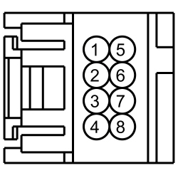 | Yes
GO to A2 . No VERIFY that BCM fuse 7 (7.5A) is OK. If OK, REPAIR the circuit. If not OK, REFER to the Wiring Diagrams manual to identify the possible causes of the circuit short. TEST the system for normal operation. | ||||||||||||
| A2 CHECK FOR GROUND TO THE EXTERIOR MIRROR CONTROL SWITCH | |||||||||||||
 | Yes
GO to A3 . No REPAIR the circuit. | ||||||||||||
| A3 CHECK THE EXTERIOR MIRROR COMMON CIRCUIT FOR A SHORT TO VOLTAGE | |||||||||||||
 | Yes
REPAIR the circuit. No GO to A4 . | ||||||||||||
| A4 CHECK THE EXTERIOR MIRROR COMMON CIRCUIT FOR A SHORT TO GROUND | |||||||||||||
 | Yes
GO to A5 . No REPAIR the circuit. | ||||||||||||
| A5 CHECK COMMON CIRCUIT FOR AN OPEN | |||||||||||||
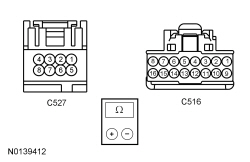 | Yes
INSTALL a new exterior mirror control switch. REFER to Exterior Mirror Control Switch . No REPAIR the circuit. | ||||||||||||
Pinpoint Test B: One Non-Memory Mirror Is Inoperative
Diagnostics in this manual assume a certain skill level and knowledge of Ford-specific diagnostic practices. Refer to Diagnostic Methods in Section 100-00 for information about these practices.
Refer to Wiring Diagrams Cell 124 , Power Mirrors for schematic and connector information.
Each exterior mirror motor has specific circuits that control the down/up and left/right movement of the glass. The motors share a common return circuit.
Possible Sources
| Test Step | Result / Action to Take | ||||||||||||||||||||||||
|---|---|---|---|---|---|---|---|---|---|---|---|---|---|---|---|---|---|---|---|---|---|---|---|---|---|
| B1 CHECK THE EXTERIOR MIRROR | |||||||||||||||||||||||||
| Yes
GO to B2 . No INSTALL a new exterior mirror control switch. REFER to Exterior Mirror Control Switch . | ||||||||||||||||||||||||
| B2 CHECK THE EXTERIOR MIRROR COMMON CIRCUIT FOR AN OPEN | |||||||||||||||||||||||||
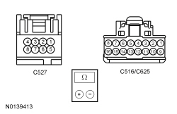 | Yes
CHECK the inoperative exterior mirror jumper harness between the vehicle harness and the exterior mirror motor for open circuits and damaged or pushed-out pins. If the jumper harness is not OK, REPAIR the jumper harness. If the jumper harness cannot be repaired, INSTALL a new exterior mirror. REFER to Exterior Mirror . If the jumper harness is OK, INSTALL a new exterior mirror motor. REFER to Exterior Mirror Motor . No REPAIR the circuit. | ||||||||||||||||||||||||
Pinpoint Test C: One Non-Memory Mirror Does Not Operate Correctly
Diagnostics in this manual assume a certain skill level and knowledge of Ford-specific diagnostic practices. Refer to Diagnostic Methods in Section 100-00 for information about these practices.
Refer to Wiring Diagrams Cell 124 , Power Mirrors for schematic and connector information.
Refer to Rear View Mirrors .
Possible Sources
| Test Step | Result / Action to Take | ||||||||||||||||||||||||
|---|---|---|---|---|---|---|---|---|---|---|---|---|---|---|---|---|---|---|---|---|---|---|---|---|---|
| C1 CHECK THE EXTERIOR MIRROR LEFT AND RIGHT MOVEMENT | |||||||||||||||||||||||||
| Yes
GO to C2 . No GO to C6 . | ||||||||||||||||||||||||
| C2 CHECK THE EXTERIOR MIRROR UP/DOWN MOTOR | |||||||||||||||||||||||||
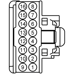 | Yes
CHECK the inoperative exterior mirror jumper harness between the vehicle harness and the exterior mirror motor for open circuits and damaged or pushed-out pins. If the jumper harness is not OK, REPAIR the jumper harness. If the jumper harness cannot be repaired, INSTALL a new exterior mirror. REFER to Exterior Mirror . If the jumper harness is OK, INSTALL a new exterior mirror motor. REFER to Exterior Mirror Motor . No GO to C3 . | ||||||||||||||||||||||||
| C3 CHECK THE EXTERIOR MIRROR UP/DOWN CIRCUIT FOR A SHORT TO VOLTAGE | |||||||||||||||||||||||||
 | Yes
REPAIR the circuit. No GO to C4 . | ||||||||||||||||||||||||
| C4 CHECK THE EXTERIOR MIRROR UP/DOWN CIRCUIT FOR A SHORT TO GROUND | |||||||||||||||||||||||||
 | Yes
GO to C5 . No REPAIR the circuit. | ||||||||||||||||||||||||
| C5 CHECK THE EXTERIOR MIRROR UP/DOWN CIRCUIT FOR AN OPEN | |||||||||||||||||||||||||
 | Yes
INSTALL a new exterior mirror control switch. REFER to Exterior Mirror Control Switch . No REPAIR the circuit. | ||||||||||||||||||||||||
| C6 CHECK THE EXTERIOR MIRROR LEFT/RIGHT MOTOR | |||||||||||||||||||||||||
 | Yes
CHECK the inoperative exterior mirror jumper harness between the vehicle harness and the exterior mirror motor for open circuits and damaged or pushed-out pins. If the jumper harness is not OK, REPAIR the jumper harness. If the jumper harness cannot be repaired, INSTALL a new exterior mirror. REFER to Exterior Mirror . If the jumper harness is OK, INSTALL a new exterior mirror motor. REFER to Exterior Mirror Motor . No GO to C7 . | ||||||||||||||||||||||||
| C7 CHECK THE EXTERIOR MIRROR LEFT/RIGHT CIRCUIT FOR A SHORT TO VOLTAGE | |||||||||||||||||||||||||
 | Yes
REPAIR the circuit. No GO to C8 . | ||||||||||||||||||||||||
| C8 CHECK THE EXTERIOR MIRROR LEFT/RIGHT CIRCUIT FOR A SHORT TO GROUND | |||||||||||||||||||||||||
 | Yes
GO to C9 . No REPAIR the circuit. | ||||||||||||||||||||||||
| C9 CHECK THE EXTERIOR MIRROR UP/DOWN CIRCUIT FOR AN OPEN | |||||||||||||||||||||||||
 | Yes
INSTALL a new exterior mirror control switch. REFER to Exterior Mirror Control Switch . No REPAIR the circuit. | ||||||||||||||||||||||||
Pinpoint Test D: The Heated Exterior Mirror is Inoperative
Diagnostics in this manual assume a certain skill level and knowledge of Ford-specific diagnostic practices. Refer to Diagnostic Methods in Section 100-00 for information about these practices.
Refer to Wiring Diagrams Cell 56 , Heated Windows for schematic and connector information.
Refer to Wiring Diagrams Cell 124 , Power Mirrors for schematic and connector information.
Refer to Rear View Mirrors .
Possible Sources
| Test Step | Result / Action to Take | ||||||||||||||||||||||||
|---|---|---|---|---|---|---|---|---|---|---|---|---|---|---|---|---|---|---|---|---|---|---|---|---|---|
| D1 CHECK THE OPERATION OF THE REAR WINDOW DEFROST SYSTEM | |||||||||||||||||||||||||
| Yes
GO to D2 . No REFER to Section 501-11 to diagnose the rear window defrost system. | ||||||||||||||||||||||||
| D2 CHECK THE OPERATION OF THE HEATED EXTERIOR REAR VIEW MIRRORS | |||||||||||||||||||||||||
| Yes
GO to D4 . No VERIFY the BJB fuse 50 (10A) is OK. If OK, GO to D3 . If not OK, REFER to the Wiring Diagrams manual to identify the possible cause of the circuit short. | ||||||||||||||||||||||||
| D3 CHECK FOR VOLTAGE TO BJB FUSE 50 (10A) | |||||||||||||||||||||||||
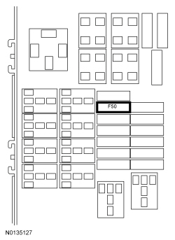 | Yes
REPAIR circuit CRD13 (GN/VT). No REPAIR circuit CRD06 (BN/YE). | ||||||||||||||||||||||||
| D4 CHECK THE VOLTAGE TO THE INOPERATIVE HEATED EXTERIOR REAR VIEW MIRROR GLASS | |||||||||||||||||||||||||
 | Yes
GO to D5 . No REPAIR the circuit. | ||||||||||||||||||||||||
| D5 CHECK THE INOPERATIVE EXTERIOR REAR VIEW MIRROR GROUND CIRCUIT FOR AN OPEN | |||||||||||||||||||||||||
 | Yes
CHECK the LH or RH exterior mirror jumper harness between the vehicle harness and the exterior mirror glass for open circuits and damaged or pushed-out pins. If the jumper harness is not OK, REPAIR the jumper harness. If the jumper harness cannot be repaired, INSTALL a new LH or RH exterior mirror. REFER to Exterior Mirror . If the jumper harness is OK, INSTALL a new LH or RH exterior mirror glass. REFER to Exterior Mirror Glass . TEST the system for normal operation. No REPAIR the circuit. | ||||||||||||||||||||||||
Pinpoint Test E: The Memory Mirror is Inoperative
Diagnostics in this manual assume a certain skill level and knowledge of Ford-specific diagnostic practices. Refer to Diagnostic Methods in Section 100-00 for information about these practices.
Refer to Wiring Diagrams Cell 124 , Power Mirrors for schematic and connector information.
The exterior mirror control switch sends voltage and ground inputs to the Driver Door Module (DDM) which controls LH mirror movement by providing the appropriate voltage and ground polarity to the LH exterior mirror up/down and left/right motors. The Driver Seat Module (DSM) controls RH mirror movement by providing the appropriate voltage and ground polarity to the RH exterior mirror up/down and left/right motors. The LH and RH exterior mirrors each contain potentiometers for up/down and left/right position status. The DDM (LH mirror) and DSM (RH mirror) supply the exterior mirror feedback potentiometers a reference voltage and reference ground. The DDM and DSM use these feedback signals to store/recall mirror positions.
DTC Fault Trigger Conditions
| DTC | Description | Fault Trigger Conditions |
|---|---|---|
| Mirror Driver Up/Down Motor Stalled | During self-test, the DDM (LH mirror) or DSM (RH mirror) attempts to operate the exterior mirror motor and uses the motor's position sensor to monitor movement. If no motor movement is sensed, the DDM or DSM disables the output after 250 milliseconds and the DTC is set. The DDM or DSM will retry motor operation on the next activation of the exterior mirror control switch. |
| Mirror Passenger Up/Down Motor Stalled | |
| Mirror Driver Right/Left Motor Stalled | During self-test, the DDM (LH mirror) or DSM (RH mirror) attempts to operate the exterior mirror motor and uses the motor's position sensor to monitor movement. If no motor movement is sensed, the DDM or DSM disables the output after 250 milliseconds and the DTC is set. The DDM or DSM will retry motor operation on the next activation of the exterior mirror control switch. |
| Mirror Passenger Right/Left Motor Stalled | |
| Mirror Driver Vertical Switch Circuit Failure | During self-test, if the DDM senses a short to ground or short to battery fault on the switch circuit, the DTC is set. During normal operation, if a fault is sensed on the circuit for greater than 2 minutes, the DTC is set as continuous. With the DTC set, any input signal on the circuit is ignored. |
| Mirror Passenger Vertical Switch Circuit Failure | |
| Mirror Driver Horizontal Switch Circuit Failure | During self-test, if the DDM senses a short to ground or short to battery fault on the switch circuit, the DTC is set. During normal operation, if a fault is sensed on the circuit for greater than 2 minutes, the DTC is set as continuous. With the DTC set, any input signal on the circuit is ignored. |
| Mirror Passenger Horizontal Switch Circuit Failure | |
| Mirror Driver Drive Circuit Failure | These DTCs set when the DDM (LH mirror) or DSM detects a short to ground or battery on either a driver or passenger motor drive circuit. |
| Mirror Passenger Drive Circuit Failure | |
| Mirror Passenger Horizontal Feedback Potentiometer Circuit Failure | These DTCs set when the DDM (LH mirror) or DSM (RH mirror) detects an open or short to ground on either a driver or passenger mirror horizontal position feedback circuit. When the DTC is set, the DDM or DSM operates the motor for 1 second then movement stops. |
| Mirror Driver Horizontal Feedback Potentiometer Circuit Failure | |
| Mirror Passenger Horizontal Feedback Potentiometer Circuit Short to Battery | These DTCs set when the DDM (LH mirror) or DSM (RH mirror) detects a short to battery on either a driver or passenger mirror horizontal position feedback circuit. When DTC is set, the DDM or DSM operates the motor for 1 second then movement stops. |
| Mirror Driver Horizontal Feedback Potentiometer Circuit Short to Battery | |
| Mirror Passenger Vertical Feedback Potentiometer Circuit Failure | These DTCs set when the DDM (LH mirror) or DSM (RH mirror) detects an open or short to ground on either a driver or passenger mirror vertical position feedback circuit. When DTC is set, the DDM or DSM operates the motor for 1 second then movement stops. |
| Mirror Driver Vertical Feedback Potentiometer Circuit Failure | |
| Mirror Passenger Vertical Feedback Potentiometer Circuit Short to Battery | These DTCs set when the DDM (LH mirror) or DSM (RH mirror) detects a short to battery on either a driver or passenger mirror vertical position feedback circuit. When DTC is set, the DDM or DSM operates the motor for 1 second then movement stops. |
| Mirror Driver Vertical Feedback Potentiometer Circuit Short to Battery |
Possible Sources
| Test Step | Result / Action to Take | ||||||||||||||||||||||||||||||||||||||||||||||||
|---|---|---|---|---|---|---|---|---|---|---|---|---|---|---|---|---|---|---|---|---|---|---|---|---|---|---|---|---|---|---|---|---|---|---|---|---|---|---|---|---|---|---|---|---|---|---|---|---|---|
| E1 CHECK POWER WINDOW OPERATION | |||||||||||||||||||||||||||||||||||||||||||||||||
| Yes
GO to E2 . No REFER to Section 501-11 to diagnose the windows. | ||||||||||||||||||||||||||||||||||||||||||||||||
| E2 RETRIEVE THE DTCs FROM THE DSM AND DDM | |||||||||||||||||||||||||||||||||||||||||||||||||
| Yes
If DTC B1667 or B1668 is present with other DTCs, DIAGNOSE the other DTCs first. If DTC B1667 or B1668 is present without other DTCs, INSPECT the LH exterior mirror motor for foreign material, damage or a binding condition. If no condition is found, GO to E9 . If DTC B1669 or B1670 is present with other DTCs, DIAGNOSE the other DTCs first. If DTC B1669 or B1670 is present without other DTCs, INSPECT the RH exterior mirror motor for foreign material, damage or a binding condition. If no condition is found, GO to E11 . For DTCs B1733, B1737, B1741 or B1745, GO to E13 . For DTC B2223, GO to E16 . For DTC B2224, GO to E18 . For DTCs B2312, B2316, B2320 or B2324, GO to E20 . For DTCs B2314, B2318, B2322 or B2326, GO to E23 . For all other DSM DTCs, REFER to Section 501-10 . For all other DDM DTCs, REFER to Section 501-14A (without IA ) or Section 501-14B (with IA ). No GO to E3 . | ||||||||||||||||||||||||||||||||||||||||||||||||
| E3 CHECK OPERATION OF THE MIRRORS FROM THE EXTERIOR MIRROR CONTROL SWITCH | |||||||||||||||||||||||||||||||||||||||||||||||||
| Yes
If the LH or RH exterior mirror operates correctly in at least one direction, GO to E8 . No If both the LH and RH exterior mirrors are inoperative, GO to E4 . | ||||||||||||||||||||||||||||||||||||||||||||||||
| E4 CHECK THE EXTERIOR MIRROR CONTROL SWITCH | |||||||||||||||||||||||||||||||||||||||||||||||||
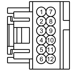 | Yes
GO to E25 . No GO to E5 . | ||||||||||||||||||||||||||||||||||||||||||||||||
| E5 CHECK THE MIRROR SWITCH COMMON CIRCUIT FOR A SHORT TO VOLTAGE | |||||||||||||||||||||||||||||||||||||||||||||||||
 | Yes
REPAIR the circuit. No GO to E6 . | ||||||||||||||||||||||||||||||||||||||||||||||||
| E6 CHECK THE MIRROR SWITCH COMMON CIRCUIT FOR A SHORT TO GROUND | |||||||||||||||||||||||||||||||||||||||||||||||||
 | Yes
GO to E7 . No REPAIR the circuit. | ||||||||||||||||||||||||||||||||||||||||||||||||
| E7 CHECK THE MIRROR SWITCH COMMON CIRCUIT FOR AN OPEN | |||||||||||||||||||||||||||||||||||||||||||||||||
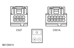 | Yes
INSTALL a new exterior mirror control switch. REFER to Exterior Mirror Control Switch . No REPAIR the circuit. | ||||||||||||||||||||||||||||||||||||||||||||||||
| E8 CHECK THE EXTERIOR MIRROR SWITCH CIRCUITS FOR AN OPEN | |||||||||||||||||||||||||||||||||||||||||||||||||
 | Yes
GO to E25 . No REPAIR the affected circuit. | ||||||||||||||||||||||||||||||||||||||||||||||||
| E9 CHECK THE LH EXTERIOR MIRROR FOR VOLTAGE WHILE COMMANDING THE DDM PIDs | |||||||||||||||||||||||||||||||||||||||||||||||||


 | Yes
CHECK the LH exterior mirror jumper harness between the vehicle harness and the exterior mirror motor for open circuits and damaged or pushed-out pins. If the jumper harness is not OK, REPAIR the jumper harness. If the jumper harness cannot be repaired, INSTALL a new LH exterior mirror. REFER to Exterior Mirror . If the jumper harness is OK, INSTALL a new LH exterior mirror motor. REFER to Exterior Mirror Motor . No GO to E10 . | ||||||||||||||||||||||||||||||||||||||||||||||||
| E10 CHECK THE LH EXTERIOR MIRROR CONTROL OUTPUT CIRCUITS FOR AN OPEN | |||||||||||||||||||||||||||||||||||||||||||||||||
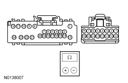 | Yes
GO to E25 . No REPAIR the circuit. | ||||||||||||||||||||||||||||||||||||||||||||||||
| E11 CHECK THE RH EXTERIOR MIRROR FOR VOLTAGE WHILE COMMANDING THE DSM PIDs | |||||||||||||||||||||||||||||||||||||||||||||||||


 | Yes
CHECK the RH exterior mirror jumper harness between the vehicle harness and the exterior mirror motor for open circuits and damaged or pushed-out pins. If the jumper harness is not OK, REPAIR the jumper harness. If the jumper harness cannot be repaired, INSTALL a new RH exterior mirror. REFER to Exterior Mirror . If the jumper harness is OK, INSTALL a new RH exterior mirror motor. REFER to Exterior Mirror Motor . No GO to E12 . | ||||||||||||||||||||||||||||||||||||||||||||||||
| E12 CHECK THE RH EXTERIOR MIRROR CONTROL OUTPUT CIRCUITS FOR AN OPEN | |||||||||||||||||||||||||||||||||||||||||||||||||
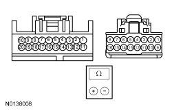 | Yes
GO to E26 . No REPAIR the circuit. | ||||||||||||||||||||||||||||||||||||||||||||||||
| E13 CHECK THE EXTERIOR MIRROR CONTROL SWITCH | |||||||||||||||||||||||||||||||||||||||||||||||||
| Yes
GO to E14 . No INSTALL a new exterior mirror control switch. REFER to Section 501-11 . | ||||||||||||||||||||||||||||||||||||||||||||||||
| E14 CHECK THE MIRROR CONTROL CIRCUITS FOR A SHORT TO VOLTAGE | |||||||||||||||||||||||||||||||||||||||||||||||||
 | Yes
REPAIR the circuit. No GO to E15 . | ||||||||||||||||||||||||||||||||||||||||||||||||
| E15 CHECK THE MIRROR CONTROL CIRCUITS FOR A SHORT TO GROUND | |||||||||||||||||||||||||||||||||||||||||||||||||
 | Yes
GO to E25 . No REPAIR the circuit. | ||||||||||||||||||||||||||||||||||||||||||||||||
| E16 CHECK THE LH EXTERIOR MIRROR CONTROL OUTPUT CIRCUITS FOR A SHORT TO VOLTAGE | |||||||||||||||||||||||||||||||||||||||||||||||||
 | Yes
REPAIR the affected circuit. No GO to E17 . | ||||||||||||||||||||||||||||||||||||||||||||||||
| E17 CHECK THE LH EXTERIOR MIRROR CONTROL OUTPUT CIRCUITS FOR A SHORT TO GROUND | |||||||||||||||||||||||||||||||||||||||||||||||||
 | Yes
GO to E24 . No REPAIR the affected circuit. | ||||||||||||||||||||||||||||||||||||||||||||||||
| E18 CHECK THE RH EXTERIOR MIRROR CONTROL OUTPUT CIRCUITS FOR A SHORT TO VOLTAGE | |||||||||||||||||||||||||||||||||||||||||||||||||
 | Yes
REPAIR the affected circuit. No GO to E19 . | ||||||||||||||||||||||||||||||||||||||||||||||||
| E19 CHECK THE RH EXTERIOR MIRROR CONTROL OUTPUT CIRCUITS FOR A SHORT TO GROUND | |||||||||||||||||||||||||||||||||||||||||||||||||
 | Yes
GO to E24 . No REPAIR the affected circuit. | ||||||||||||||||||||||||||||||||||||||||||||||||
| E20 CHECK THE MIRROR POSITION SENSOR CIRCUITS FOR A SHORT TO GROUND | |||||||||||||||||||||||||||||||||||||||||||||||||

 | Yes
GO to E21 . No REPAIR the affected circuit. | ||||||||||||||||||||||||||||||||||||||||||||||||
| E21 CHECK THE MIRROR POSITION SENSOR CIRCUITS FOR AN OPEN | |||||||||||||||||||||||||||||||||||||||||||||||||
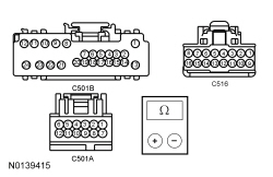
 | Yes
GO to E22 . No REPAIR the affected circuit. | ||||||||||||||||||||||||||||||||||||||||||||||||
| E22 CHECK THE MIRROR POSITION SENSOR FEED AND RETURN FROM THE DSM | |||||||||||||||||||||||||||||||||||||||||||||||||
 | Yes
For DTC B2312 or B2316, CHECK the RH exterior mirror jumper harness between the vehicle harness and the exterior mirror motors for open or shorted circuits and damaged or pushed-out pins. For DTC B2320 or B2324, CHECK the LH exterior mirror jumper harness between the vehicle harness and the exterior mirror motors for open or shorted circuits and damaged or pushed-out pins. If the jumper harness is not OK, REPAIR the jumper harness. If the jumper harness cannot be repaired, INSTALL a new RH exterior mirror. REFER to Exterior Mirror . If the jumper harness is OK, INSTALL a new RH exterior mirror motor. REFER to Exterior Mirror Motor . No For DDM DTC B2320 or B2324, GO to E25 . For DSM DTC B2320 or B2324, GO to E26 . | ||||||||||||||||||||||||||||||||||||||||||||||||
| E23 CHECK THE MIRROR POSITION SENSOR CIRCUITS FOR A SHORT TO VOLTAGE | |||||||||||||||||||||||||||||||||||||||||||||||||

 | Yes
REPAIR the affected circuit. No For DTC B2314 or B2318, CHECK the RH exterior mirror jumper harness between the vehicle harness and the exterior mirror motors for open or shorted circuits and damaged or pushed-out pins. For DTC B2322 or B2326, CHECK the LH exterior mirror jumper harness between the vehicle harness and the exterior mirror motors for open or shorted circuits and damaged or pushed-out pins. If the jumper harness is not OK, REPAIR the jumper harness. If the jumper harness cannot be repaired, INSTALL a new RH exterior mirror. REFER to Exterior Mirror . If the jumper harness is OK, INSTALL a new RH exterior mirror motor. REFER to Exterior Mirror Motor . | ||||||||||||||||||||||||||||||||||||||||||||||||
| E24 CHECK THE EXTERIOR MIRROR | |||||||||||||||||||||||||||||||||||||||||||||||||
| Yes
For DDM DTC B2223, GO to E25 . For DSM DTC B2224, GO to E26 . No CHECK the inoperative exterior mirror jumper harness between the vehicle harness and the exterior mirror motor for open or short circuits and damaged or pushed-out pins. If the jumper harness is not OK, REPAIR the jumper harness. If the jumper harness cannot be repaired, INSTALL a new exterior mirror. REFER to Exterior Mirror . If the jumper harness is OK, INSTALL a new exterior mirror motor. REFER to Exterior Mirror Motor . | ||||||||||||||||||||||||||||||||||||||||||||||||
| E25 CHECK FOR CORRECT DDM OPERATION | |||||||||||||||||||||||||||||||||||||||||||||||||
| Yes
CHECK On-Line Automotive Service Information System (OASIS) for any applicable TSBs. If a TSB exists for this concern, DISCONTINUE this test and FOLLOW TSB instructions. If no TSBs address this concern, INSTALL a new DDM . REFER to Section 501-14A (without IA ) or Section 501-14B (with IA ). No The system is operating correctly at this time. The concern may have been caused by module connections. ADDRESS the root cause of any connector or pin issues. | ||||||||||||||||||||||||||||||||||||||||||||||||
| E26 CHECK FOR CORRECT DSM OPERATION | |||||||||||||||||||||||||||||||||||||||||||||||||
| Yes
CHECK On-Line Automotive Service Information System (OASIS) for any applicable TSBs. If a TSB exists for this concern, DISCONTINUE this test and FOLLOW TSB instructions. If no TSBs address this concern, INSTALL a new DSM . REFER to Section 501-10 . No The system is operating correctly at this time. The concern may have been caused by module connections. ADDRESS the root cause of any connector or pin issues. | ||||||||||||||||||||||||||||||||||||||||||||||||
Pinpoint Test F: The Power Folding Mirrors Do Not Operate Or Do Not Operate Correctly
Diagnostics in this manual assume a certain skill level and knowledge of Ford-specific diagnostic practices. Refer to Diagnostic Methods in Section 100-00 for information about these practices.
Refer to Wiring Diagrams Cell 124 , Power Mirrors for schematic and connector information.
Refer to Rear View Mirrors .
DTC Fault Trigger Conditions
| DTC | Description | Fault Trigger Conditions |
|---|---|---|
| Mirror Power Fold Switch Input Short to Battery | This DTC sets when the DSM detects a short to battery on the power fold switch circuit. |
Possible Sources
| Test Step | Result / Action to Take | ||||||||||||||||
|---|---|---|---|---|---|---|---|---|---|---|---|---|---|---|---|---|---|
| F1 CHECK THE RECORDED RESULTS FROM THE DSM ON-DEMAND SELF-TEST | |||||||||||||||||
| Yes
GO to F10 . No GO to F2 . | ||||||||||||||||
| F2 CHECK THE OPERATION OF THE POWER FOLDING MIRRORS | |||||||||||||||||
| Yes
The system is operating correctly at this time. Concern may have been caused by a loose or corroded connector or the power folding mirror power lockout feature may have been active. TEST the system for normal operation. No If both the LH and RH power folding mirrors are inoperative, GO to F3 . If only the LH power folding mirror is inoperative, GO to F11 . If only the RH power folding mirror is inoperative, GO to F12 . | ||||||||||||||||
| F3 CHECK THE EXTERIOR MIRROR CONTROL SWITCH | |||||||||||||||||
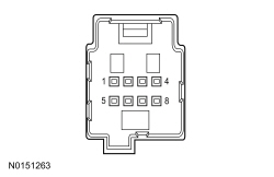 | Yes
GO to F4 . No INSTALL a new exterior mirror control switch. REFER to Exterior Mirror Control Switch . | ||||||||||||||||
| F4 CHECK THE MIRROR SWITCH COMMON CIRCUT FOR AN OPEN BETWEEN THE EXTERIOR MIRROR CONTROL SWITCH AND THE DSM | |||||||||||||||||
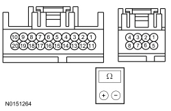 | Yes
GO to F5 . No REPAIR the circuit. | ||||||||||||||||
| F5 CHECK THE FOLDING MOTOR CONTROL CIRCUIT FOR A SHORT TO GROUND | |||||||||||||||||
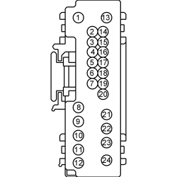 | Yes
GO to F6 . No REPAIR the circuit. | ||||||||||||||||
| F6 CHECK THE FOLDING MOTOR CONTROL CIRCUIT FOR AN OPEN | |||||||||||||||||
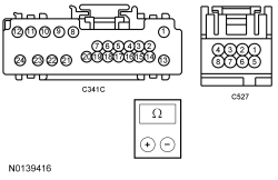 | Yes
GO to F7 . No REPAIR the circuit. SYNCHRONIZE the power folding mirrors. REFER to Motor Synchronization — Exterior, Power Folding . | ||||||||||||||||
| F7 CHECK THE FOLDING MIRROR OUTPUT CIRCUITS FOR A SHORT TO VOLTAGE | |||||||||||||||||
 | Yes
REPAIR the affected circuit. SYNCHRONIZE the power folding mirrors. REFER to Motor Synchronization — Exterior, Power Folding . No GO to F8 . | ||||||||||||||||
| F8 CHECK THE FOLDING MIRROR OUTPUT CIRCUITS FOR AN OPEN | |||||||||||||||||
 | Yes
GO to F9 . No REPAIR the affected circuit. SYNCHRONIZE the power folding mirrors. REFER to Motor Synchronization — Exterior, Power Folding . | ||||||||||||||||
| F9 CHECK THE FOLDING MIRROR OUTPUT CIRCUITS FOR A SHORT TO GROUND | |||||||||||||||||
 | Yes
GO to F13 . No REPAIR the affected circuit. SYNCHRONIZE the power folding mirrors. REFER to Motor Synchronization — Exterior, Power Folding . | ||||||||||||||||
| F10 CHECK THE FOLDING MOTOR CONTROL CIRCUIT FOR A SHORT TO VOLTAGE | |||||||||||||||||
 | Yes
REPAIR the affected circuit. SYNCHRONIZE the power folding mirrors. REFER to Motor Synchronization — Exterior, Power Folding . No GO to F13 . | ||||||||||||||||
| F11 CHECK THE LH POWER FOLD EXTERIOR MIRROR CIRCUITS FOR AN OPEN | |||||||||||||||||
 | Yes
CHECK the LH exterior mirror jumper harness between the vehicle harness and the exterior mirror glass for open circuits and damaged or pushed-out pins. If the jumper harness is not OK, REPAIR the jumper harness. If the jumper harness cannot be repaired, INSTALL a new LH exterior mirror. REFER to Exterior Mirror . SYNCHRONIZE the power folding mirrors. REFER to Motor Synchronization — Exterior, Power Folding . No REPAIR the affected circuit. SYNCHRONIZE the power folding mirrors. REFER to Motor Synchronization — Exterior, Power Folding . | ||||||||||||||||
| F12 CHECK THE RH POWER FOLD EXTERIOR MIRROR CIRCUIT FOR AN OPEN | |||||||||||||||||
 | Yes
CHECK the RH exterior mirror jumper harness between the vehicle harness and the exterior mirror glass for open circuits and damaged or pushed-out pins. If the jumper harness is not OK, REPAIR the jumper harness. If the jumper harness cannot be repaired, INSTALL a new RH exterior mirror. REFER to Exterior Mirror . SYNCHRONIZE the power folding mirrors. REFER to Motor Synchronization — Exterior, Power Folding . No REPAIR the affected circuit. SYNCHRONIZE the power folding mirrors. REFER to Motor Synchronization — Exterior, Power Folding . | ||||||||||||||||
| F13 CHECK FOR CORRECT DSM OPERATION | |||||||||||||||||
| Yes
CHECK On-Line Automotive Service Information System (OASIS) for any applicable TSBs. If a TSB exists for this concern, DISCONTINUE this test and FOLLOW TSB instructions. If no TSBs address this concern, INSTALL a new DSM . REFER to Section 501-10 . No The system is operating correctly at this time. The concern may have been caused by module connections. ADDRESS the root cause of any connector or pin issues. | ||||||||||||||||