SGT27000

105-R025D or equivalent

FLU77-4 or equivalent
SECTION 206-06: Hydraulic Brake Actuation
| 2014 Flex Workshop Manual
|
DIAGNOSIS AND TESTING
| Procedure revision date: 05/02/2013
|
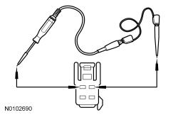
 | Circuit Tester / Test Light
SGT27000 |
 | Flex Probe Kit
105-R025D or equivalent |
 | Fluke 77-IV Digital Multimeter
FLU77-4 or equivalent |
Diagnostic Routines
Pinpoint Test A: The Adjustable Pedals Only Move in 1-Second Intervals
Diagnostics in this manual assume a certain skill level and knowledge of Ford-specific diagnostic practices. Refer to Diagnostic Methods in Section 100-00 for information about these practices.
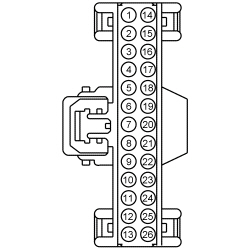
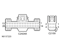
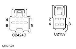
Refer to Wiring Diagrams Cell 127 , Adjustable Pedals for schematic and connector information.
The SCCM uses a Hall-effect sensor integral to the motor to identify the current pedal position. The SCCM sends a reference voltage along the sensor feed circuit, through the Hall-effect sensor and back to the SCCM along the signal return circuit.
When one or more of the following DTCs set, the adjustable pedals enter a “jog mode”. The memory system recall will not function from either the memory set switch or the RKE transmitter while the pedals are in jog mode. The motor moves the pedals for only one second regardless of the length of time the adjustable pedals control switch is actually pressed.
DTC Fault Trigger Conditions
| DTC | Description | Fault Trigger Conditions |
|---|---|---|
| Adjustable Pedal Position Feedback Sensor: Circuit Short to Ground | Sets when the SCCM detects a short to ground on the Hall-effect sensor feed and/or return circuits. The SCCM continually checks for faults during normal operation when the ignition is ON and during the on-demand self test. |
| Adjustable Pedal Position Feedback Sensor: Circuit Short to Battery | Sets when the SCCM detects a short to voltage on the Hall-effect sensor feed and/or return circuits. The SCCM continually checks for faults during normal operation when the ignition is ON and during the on-demand self test. |
| Test Step | Result / Action to Take | ||||||||||||||||
|---|---|---|---|---|---|---|---|---|---|---|---|---|---|---|---|---|---|
| A1 RETRIEVE THE SCCM DTCs | |||||||||||||||||
| Yes
GO to A2 . No If no DTCs were retrieved, CONFIGURE the SCCM using As-Built data. If other SCCM DTCs were retrieved, REFER to the DTC Chart in this section. | ||||||||||||||||
| A2 CHECK THE SCCM HALL-EFFECT CIRCUITS FOR A SHORT TO VOLTAGE | |||||||||||||||||
 | Yes
REPAIR the affected circuit(s). No GO to A3 . | ||||||||||||||||
| A3 CHECK THE SCCM HALL-EFFECT CIRCUITS FOR A SHORT TO GROUND | |||||||||||||||||
 | Yes
GO to A4 . No REPAIR the affected circuit(s). | ||||||||||||||||
| A4 CHECK THE SCCM HALL-EFFECT CIRCUITS FOR AN OPEN | |||||||||||||||||
 | Yes
GO to A5 . No REPAIR the affected circuit(s). | ||||||||||||||||
| A5 CHECK THE SCCM HALL-EFFECT CIRCUITS FOR A SHORT TOGETHER | |||||||||||||||||
 | Yes
INSTALL a new brake pedal and bracket. REFER to Brake Pedal and Bracket in this section. CLEAR the DTCs. REPEAT the self-test. If DTC B1368:11 or B1368:12 is retrieved again, INSTALL a new SCCM . REFER to Section 211-05 . No REPAIR the affected circuit(s). | ||||||||||||||||
Pinpoint Test B: The Adjustable Pedals are Inoperative or Do Not Operate Correctly — Using the Adjustable Pedals Control Switch
Diagnostics in this manual assume a certain skill level and knowledge of Ford-specific diagnostic practices. Refer to Diagnostic Methods in Section 100-00 for information about these practices.
Refer to Wiring Diagrams Cell 127 , Adjustable Pedals for schematic and connector information.
The SCCM receives fused battery voltage from the BCM .
Pressing the adjustable pedals control switch causes the SCCM to send current along one circuit to the adjustable pedal motor. The current returns to the SCCM along another circuit and is grounded through the SCCM , this moves the pedals in the desired direction. Pressing the adjustable pedals control switch in the opposite direction reverses the current flow through the circuits and moves the pedals in the opposite direction.
DTC Fault Trigger Conditions
| DTC | Description | Fault Trigger Conditions |
|---|---|---|
| Pedal Adjustment Motor: Circuit Current Below Threshold | Sets when the SCCM detects current flow to the adjustable pedal motor below a preset limit. The SCCM checks for this fault during the on-demand self test. |
| Pedal Adjustment Motor: Circuit Current Above Threshold | Sets when the SCCM detects current flow to the adjustable pedal motor above a preset limit. The SCCM continually checks for this fault during normal operation when the ignition is ON and during the on-demand self test. |
| Pedal Adjustment Motor: Actuator Stuck | Sets when the SCCM detects current flow to the adjustable pedal motor is within a specific range but above a preset limit. The SCCM checks for this fault during the on-demand self test. |
Inspect BCM fuses 23 (15A) and 24 (15A).
| Test Step | Result / Action to Take | ||||||||||||||||
|---|---|---|---|---|---|---|---|---|---|---|---|---|---|---|---|---|---|
| B1 CHECK THE ADJUSTABLE PEDAL MOTOR AND CABLE INSTALLATION | |||||||||||||||||
| Yes
GO to B2 . No CORRECT the adjustable pedal motor and/or cable installation. | ||||||||||||||||
| B2 INSPECT FOR FOREIGN OBJECTS OR MATERIAL | |||||||||||||||||
| Yes
GO to B3 . No REMOVE the foreign material. | ||||||||||||||||
| B3 CHECK THE SCCM LOGIC VOLTAGE INPUT | |||||||||||||||||
 | Yes
GO to B4 . No VERIFY BCM fuse 23 (15A) is OK. If OK, REPAIR the circuit. If not OK, REFER to the Wiring Diagrams manual to identify the cause of the circuit short. | ||||||||||||||||
| B4 CHECK THE SCCM HIGH CURRENT VOLTAGE INPUT | |||||||||||||||||
 | Yes
GO to B5 . No VERIFY BCM fuse 24 (15A) is OK. If OK, REPAIR the circuit. If not OK, REFER to the Wiring Diagrams manual to identify the cause of the circuit short. | ||||||||||||||||
| B5 CHECK THE SCCM LOGIC GROUND CIRCUIT FOR AN OPEN | |||||||||||||||||
 | Yes
GO to B6 . No REPAIR the circuit. | ||||||||||||||||
| B6 CHECK THE SCCM HIGH CURRENT GROUND CIRCUIT FOR AN OPEN | |||||||||||||||||
 | Yes
GO to B7 . No REPAIR the circuit. | ||||||||||||||||
| B7 CHECK THE ADJUSTABLE PEDAL MOTOR CIRCUITS FOR A SHORT TO VOLTAGE | |||||||||||||||||
 | Yes
REPAIR the affected circuit(s). No GO to B8 . | ||||||||||||||||
| B8 CHECK THE ADJUSTABLE PEDAL MOTOR CIRCUITS FOR A SHORT TO GROUND | |||||||||||||||||
 | Yes
GO to B9 . No REPAIR the affected circuit(s). | ||||||||||||||||
| B9 CHECK THE ADJUSTABLE PEDAL MOTOR CIRCUITS FOR AN OPEN | |||||||||||||||||
 | Yes
GO to B10 . No REPAIR the affected circuit(s). | ||||||||||||||||
| B10 CHECK THE SCCM OUTPUT | |||||||||||||||||
 | Yes
INSTALL a new brake pedal assembly. REFER to Brake Pedal and Bracket in this section. No INSTALL a new adjustable pedals control switch. REFER to Adjustable Pedals Control Switch in this section. CLEAR the DTCs. REPEAT the self-test. If DTCs B137D:18, 19 or 71 return, or if the adjustable pedals are still inoperative/do not operate correctly, GO to B11 . | ||||||||||||||||
| B11 CHECK THE SCCM FOR CORRECT OPERATION | |||||||||||||||||
| Yes
CHECK OASIS for any applicable TSBs. If a TSB exists for this concern, DISCONTINUE this test and FOLLOW the TSB instructions. If no TSBs address this concern, INSTALL a new SCCM . REFER to Section 211-05 . No The system is operating correctly at this time. The concern may have been caused by module connections. ADDRESS the root cause of any connector or pin issues. | ||||||||||||||||
Pinpoint Test C: The Adjustable Pedals are Inoperative or Do Not Operate Correctly - Using the Memory SET Switch Buttons or the RKE Transmitter
Diagnostics in this manual assume a certain skill level and knowledge of Ford-specific diagnostic practices. Refer to Diagnostic Methods in Section 100-00 for information about these practices.
Refer to Wiring Diagrams Cell 127 , Adjustable Pedals for schematic and connector information.
Pressing the memory SET switch causes the DSM to communicate the desired pedal position to the BCM on the MS-CAN . The BCM acts as a gateway module and relays the message to the SCCM along the HS-CAN . The SCCM sends current to the adjustable pedal motor to move the pedals to the required position.
Pressing the unlock button on the RKE transmitter sends a radio frequency signal to the TPM module. The TPM module sends a message to the RFA module along a dedicated LIN . The RFA module then sends a message to the BCM along the MS-CAN . The BCM acts as a gateway module and relays the message to the SCCM along the HS-CAN . The SCCM sends current to the adjustable pedal motor to move the pedals to the position programmed to the key.
| Test Step | Result / Action to Take | ||||||||||||||||||||||||||||||||
|---|---|---|---|---|---|---|---|---|---|---|---|---|---|---|---|---|---|---|---|---|---|---|---|---|---|---|---|---|---|---|---|---|---|
| C1 CHECK THE ADJUSTABLE PEDAL OPERATION WITH THE ADJUSTABLE PEDALS CONTROL SWITCH | |||||||||||||||||||||||||||||||||
| Yes
GO to C2 . No If the pedals do not move at all using the switch, GO to Pinpoint Test B . If the pedals only move in 1 second intervals regardless of switch operation, GO to Pinpoint Test A . | ||||||||||||||||||||||||||||||||
| C2 CHECK THE MEMORY SYSTEM OPERATION | |||||||||||||||||||||||||||||||||
| Yes
GO to C3 . No If all 4 items do not move, REFER to Section 501-10 to diagnose the memory SET switch. If both the adjustable pedals and the steering column do not move or only the adjustable pedals do not move, GO to C4 . If only the driver seat does not move, REFER to Section 501-10 to diagnose the driver seat. If only the exterior mirrors do not move, REFER to Section 501-09 to diagnose the memory mirrors. If only the steering column does not move, REFER to Section 211-04 to diagnose the power adjustable steering column. | ||||||||||||||||||||||||||||||||
| C3 CHECK THE RKE OPERATION | |||||||||||||||||||||||||||||||||
| Yes
The system is operating correctly at this time. No If all 4 items do not move, REFER to Section 501-14A or Section 501-14B to diagnose the RKE transmitter/ IA key. If both the adjustable pedals and the steering column do not move or only the adjustable pedals do not move, GO to C4 . If only the driver seat does not move, REFER to Section 501-10 to diagnose the driver seat. If only the exterior mirrors do not move, REFER to Section 501-09 to diagnose the memory mirrors. If only the steering column does not move, REFER to Section 211-04 to diagnose the power adjustable steering column. | ||||||||||||||||||||||||||||||||
| C4 CHECK FOR DSM OR BCM DTCs | |||||||||||||||||||||||||||||||||
| Yes
For BCM DTCs, REFER to Section 419-10 . For DSM DTCs, REFER to Section 501-10 . No GO to C5 . | ||||||||||||||||||||||||||||||||
| C5 CHECK THE ADJUSTABLE PEDAL MOTOR AND HALL-EFFECT SENSOR CIRCUITS FOR A SHORT TO VOLTAGE | |||||||||||||||||||||||||||||||||
 | Yes
REPAIR the affected circuit(s). No GO to C6 . | ||||||||||||||||||||||||||||||||
| C6 CHECK THE ADJUSTABLE PEDAL MOTOR AND HALL-EFFECT SENSOR CIRCUITS FOR A SHORT TO GROUND | |||||||||||||||||||||||||||||||||
 | Yes
GO to C7 . No REPAIR the affected circuit(s). | ||||||||||||||||||||||||||||||||
| C7 CHECK THE ADJUSTABLE PEDAL MOTOR CIRCUITS FOR AN OPEN | |||||||||||||||||||||||||||||||||
 | Yes
GO to C8 . No REPAIR the affected circuit(s). | ||||||||||||||||||||||||||||||||
| C8 CHECK THE ADJUSTABLE PEDAL MOTOR HALL-EFFECT SENSOR CIRCUITS FOR AN OPEN | |||||||||||||||||||||||||||||||||
 | Yes
GO to C9 . No REPAIR the affected circuit(s). | ||||||||||||||||||||||||||||||||
| C9 CHECK THE ADJUSTABLE PEDAL MOTOR AND HALL-EFFECT SENSOR CIRCUITS FOR A SHORT TOGETHER | |||||||||||||||||||||||||||||||||
 | Yes
CONFIGURE the SCCM using As-built data and TEST the system for normal operation. If the adjustable pedals do not operate correctly, INSTALL a new brake pedal assembly. REFER to Brake Pedal and Bracket in this section. No REPAIR the affected circuit(s). | ||||||||||||||||||||||||||||||||