SECTION 307-01: Automatic Transmission — 6F50/6F55
2014 Flex Workshop Manual
REMOVAL AND INSTALLATION
Procedure revision date: 05/02/2013

Solenoid Body Assembly

Removal

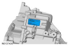
NOTE: The PCM must be updated with a new solenoid body strategy data file and solenoid body identification anytime a new solenoid body is installed. A new solenoid body service tag must be installed over the current solenoid body service tag on top of the transmission case.

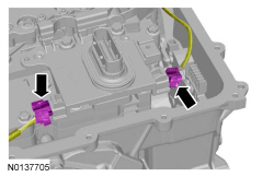
  1. With the vehicle in NEUTRAL, position it on a hoist. For additional information, refer to Section 100-02 .
  1. Remove the main control cover. For additional information, refer to Main Control Cover — 3.5L GTDI or Main Control Cover — 3.5L Ti-VCT in this section.
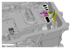
  1. Slide the TR sensor electrical connector lock tab over.
  1. NOTICE: Handle the solenoid body with care or damage to the solenoid body may occur.
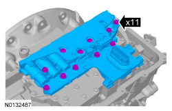
Installation

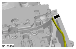
  1. NOTICE: Make sure not to pinch the TSS , OSS or TR sensor wiring harnesses behind the solenoid body when positioning the solenoid body in place.

    Hand-tighten only.
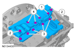
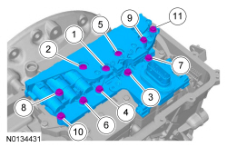
    1. 42 mm (1.653 in) bolt
    1. 63 mm (2.48 in) bolts
    1. 80 mm (3.149 in) bolts
    1. 95 mm (3.74 in) bolts
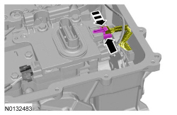
  1. Connect the TR sensor electrical connector and slide the lock tab to the LOCK position.
  1. Install the main control cover. For additional information, refer to Main Control Cover — 3.5L GTDI or Main Control Cover — 3.5L Ti-VCT in this section.
  1. Wipe the surface of the existing solenoid body strategy tag on top of the transmission case clean and install the new solenoid body strategy tag (supplied with the solenoid body service kit) over it.
  1. Download a new solenoid body strategy to the PCM. For additional information, refer to Solenoid Body Strategy Download in this section.