SECTION 307-01: Automatic Transmission — 6F50/6F55
2014 Flex Workshop Manual
DISASSEMBLY AND ASSEMBLY
Procedure revision date: 05/07/2013

Transaxle — Overhaul


Special Tool(s)
Compressor, Forward Clutch Spring
(includes 307-574/1 and 307-574/2)
Compressor, Forward/Intermediate Spring
307-584 (includes 307-584/1 and 307-584/2)
Compressor, Overdrive Clutch, Balance Piston and Direct Clutch
307-589 (includes 307-589/1 and 307-589/2)
Converter Seal Installer
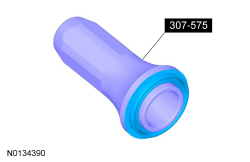
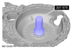
307-575
Dial Indicator Gauge with Holding Fixture
100-002 (TOOL-4201-C)
Handle
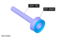
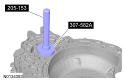
205-153 (T80T-4000-W)
Holding Fixture
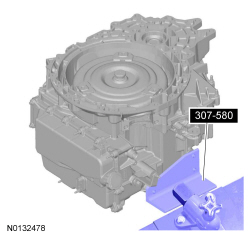
307-580
Input Shaft Support Seal Installer (Back Plate, Multiple Rings)
307-578 (includes 307-578/1, 307-578/2 and 307-578/3)
Installer, Cover Axle Seal
307-582A
Manual Lever Seal Installer
307-581
Remover, TRS Retaining Pin
307-696
Retainer, Torque Converter
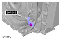
307-346
Reverse Clutch Piston and Retaining Ring Set
307-588 (includes 307-588/1, 307-588/2 and 307-588/3)
Slide Hammer
100-001 (T50T-100-A)
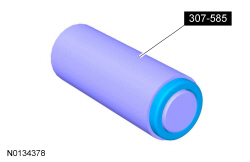
Support Seal Installer
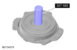
307-585
Support Solid Seal Installer (Single Seal)
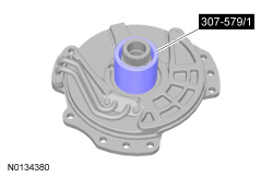
307-579 (includes 307-579/1, 307-579/2 and 307-579/3)

Material
Item Specification
Motorcraft® MERCON® LV Automatic Transmission Fluid
XT-10-QLVC (US); CXT-10-LV12 (Canada)
MERCON® LV
Ultra Silicone Sealant
TA-29

 
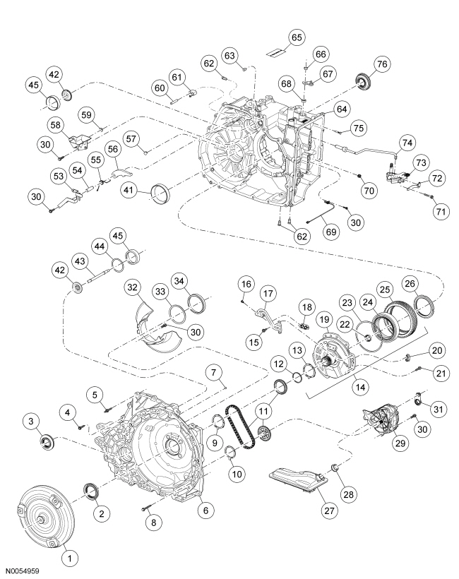
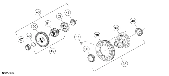
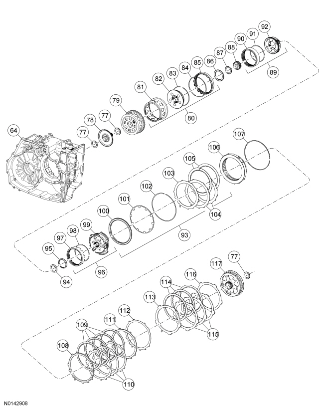
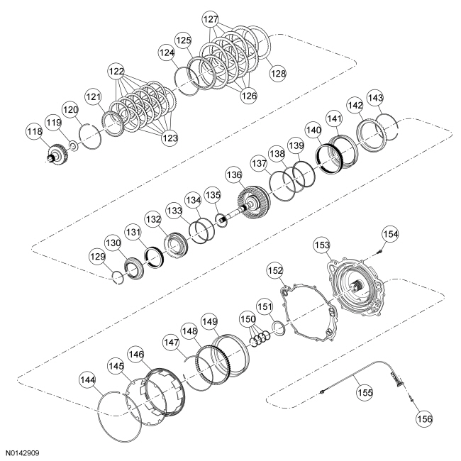
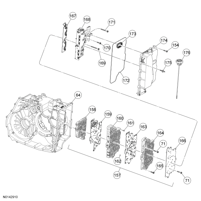
Disassembled Views


Item Part Number Description
1 7902 Torque converter assembly
2 7F401 Seal assembly — converter hub
3 1177 Seal assembly — transmission differential (front)
4 7J287 Bolt — M8 x 30 (converter housing)
5 W704941 Studbolt — M8 x 30 (converter housing)
6 7005 Torque converter housing
7 7H389 Plug — transmission orifice cup
8 W711931 Bolt — torque converter housing
9 7G099 Washer — drive sprocket thrust
10 7G273 Washer — driven sprocket support thrust
11 7G249 Sprocket and chain assembly — pump
12 7L323 Seal — support assembly-to-torque converter
13 7D014 Washer — stator support thrust
14 7A108 Support and gear assembly — stator
15 7J284 Bolt — hex-head stator support feed tube
16 7J330 Bolt — Torx®-head stator support feed tube
17 7N147 Transmission fluid feed tube assembly — stator support
18 7J246 Gasket — feed tube
19 7F363 Support assembly — torque converter reactor
20 7J246 Seal — stator support assembly
21 7J285 Bolt — M8 x 25
22 7048 Seal assembly — input shaft
23 7N281 Ring — input bearing retainer
24 7A452 Bearing assembly — main drive gear front
25 7F342 Gear — final drive input
26 7B364 Nut — bearing retainer
27 7A098 Filter — transmission fluid
28 7Z302 Seal — transmission fluid filter
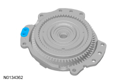
29 7A103 Pump assembly — transmission fluid
30 7J283 Bolts — M6 x 25
31 7A248 Seal — pump
32 7978 Baffle — sump
33 4067 Shim — transmission differential bearing
34 4222 Cup — differential bearing
35 7F465 Differential and gear assembly
36 4221 Bearing — differential assembly
37 7J286 Bolt — M10 x 25
38 7F343 Gear — transmission final drive output
39 4207 Gear and case — differential assembly
40 4221 Bearing — differential assembly
41 4222 Cup — differential bearing
42 7L276 Fluid dams — transfer shaft tube
43 7A209 Tube — transfer shaft
44 7H367 Shim — transfer shaft roller bearing
45 7H344 Cups — transfer shaft roller bearing
46 7H348 Gear and bearing assembly — transfer shaft
47 7H338 Cone and roller assembly — transfer shaft bearing
48 7059 Ring — transmission final drive retaining
49 7H348 Gear assembly — transfer shaft
50 7H349 Gear — transfer shaft input
51 7H346 Gear — transfer shaft output
52 7A233 Gear — output shaft parking
53 7D419 Plate — parking rod guide
54 7D071 Shaft — parking pawl
55 7D070 Spring — parking pawl return
56 7A441 Pawl — parking brake
57 7H389 Plug — transmission case orifice
58 7J387 Reservoir — transmission fluid
59 7L280 Seal — transmission fluid reservoir
60 7D412 Pin — parking pawl abutment
61 7G101 Abutment — parking pawl actuator
62 7A010 Plugs — transmission drain
63 7B362 Pin — transmission case dowel
64 7005 Case
65 7G342 Tag — transmission service identification
66 W711892-S441 Nut — M10
67 7A256 Lever — manual control
68 7F337 Seal assembly — manual control shaft
69 7H103 Sensor assembly — OSS
70 7N266 Seal — valve body
71 7J282 Bolts — M6 x 63
72 7E332 Spring assembly — manual valve detent
73 7H557 Sensor — TR
74 7A232 Rod assembly — park pawl actuator
75 7B210 Pin — manual control lever
76 1177 Seal — transmission differential
77 7M102 Bearing assembly — thrust
78 7B067 Hub assembly — planetary carrier
79 7D064 Sun gear and shell assembly — planetary carrier
80 7D491 Carrier and gear assembly — planetary
81 7M022 Shell — planetary carrier
82 7N470 Carrier — planetary gear
83 7L487 Ring — planetary carrier guide
84 7C122 Snap ring — planetary carrier
85 7G211 Gear — front planetary ring
86 7H375 Bearing and race assembly — forward planetary carrier thrust
87 7F241 Bearing and race assembly — forward planetary sun gear thrust
88 7G231 Gear — forward planetary sun
89 7L192 Carrier and ring gear assembly — forward planetary
90 7A153 Ring gear — planetary
91 7H318 Retainer — snap ring
92 7D055 Carrier assembly — forward planetary
93 Clutch assembly — forward
94 7C096 Bearing — forward planetary sun gear thrust (rear)
95 7G177 Bearing — front planetary carrier thrust
96 7D491 Gear and carrier assembly — front
97 7D392 Ring gear assembly — forward
98 7H361 Snap ring — forward planetary ring gear
99 7G226 Carrier — front planetary gear
100 7A262 Piston assembly — forward clutch
101 7B070 Spring — forward clutch piston return
102 7H365 Ring — forward clutch balance piston snap
103 7B070 Spring — forward clutch cushion
104 7B442 Plates — forward clutch (steel)
105 7B164 Plates — forward clutch (friction)
106 7A089 Clutch — low one-way
107 7D483 Ring — low OWC
108 7B066 Plate — low reverse clutch pressure
109 7B164 Plates — low reverse clutch (friction)
110 7B442 Plates — low reverse clutch (steel)
111 7B066 Plate — low reverse clutch pressure
112 7J701 Spring — low reverse clutch cushion (if equipped)
113 7B066 Plate — intermediate clutch pressure
114 7B164 Plates — intermediate clutch (friction)
115 7B442 Plates — intermediate clutch (steel)
116 7E085 Spring — intermediate clutch cushion
117 7A019 Sun gear and shell assembly — front planetary gear assembly
118 7H351 Hub assembly — direct clutch
119 7C096 Bearing — direct clutch hub thrust
120 7D483 Snap ring — overdrive clutch
121 7B066 Plate — overdrive pressure
122 7B164 Plates — overdrive pressure (friction)
123 7B442 Plates — overdrive pressure (steel)
124 7D483 Snap ring — direct clutch
125 7B066 Plate — direct clutch pressure
126 7B442 Plates — direct clutch (friction)
127 7B164 Plates — direct clutch (steel)
128 7E085 Spring — direct clutch wave
129 7C122 Snap ring — balance piston
130 7H360 Piston — balance
131 7F222 Spring — overdrive clutch piston return
132 7A262 Piston — overdrive clutch
133 7A548 Seal — overdrive clutch piston outer (front)
134 7A548 Seal — overdrive clutch piston outer (rear)
135 7A548 Seal — overdrive clutch piston inner
136 7G384 Hub and shaft assembly — input direct and overdrive clutch
137 7A548 Seal — direct clutch piston outer
138 7C099 Seal — direct clutch piston inner (front)
139 7C099 Seal — direct clutch piston inner (rear)
140 7F235 Return spring assembly — direct clutch
141 7A262 Piston assembly — direct clutch
142 7F283 Cylinder — direct clutch piston
143 7C122 Snap ring — direct clutch piston cylinder
144 7C122 Snap ring — reverse clutch piston return spring
145 7B070 Spring — reverse clutch piston return
146 7D402 Piston — reverse clutch
147 7D483 Snap ring — intermediate clutch return spring
148 7F222 Spring — intermediate clutch piston return
149 7E005 Piston — intermediate clutch
150 7D019 Seals — transmission cover
151 7H026 Bearing — turbine shaft thrust
152 7223 Gasket — cover assembly
153 7222 Cover assembly
154 7J289 Bolts — M6 x 30
155 7M101 Sensor assembly — TSS
156 7J356 Bolt — M6 x 25
157 7A100 Body assembly — main control valve
158 7A099 Body assembly — lower main control valve
159 7Z490 Plate assembly — lower valve body separator
160 7A091 Body — main control valve
161 7B431 Pin — transfer plate alignment
162 7E195 Ball — check
163 7Z490 Plate — transfer plate separator
164 7H195 Plate — transfer
165 7J291 Bolt — M6 x 35
166 7Z490 Cover assembly — main control valve body
167 7H200 Plate — solenoid filter
168 7G391 Body assembly — solenoid
169 7J295 Bolt — M6 x 95
170 7J364 Bolt — M6 x 42
171 7J293 Bolt — M6 x 80
172 7F396 Gasket — main control cover
173 7B329 Seal — solenoid body-to-main control cover
174 7G004 Cover assembly — main control
175 W708442 Stud — hex flange
176 7A020 Indicator — transmission fluid level

All vehicles

  1. Special Tool(s): Holding Fixture 307-580
  1. Special Tool(s): Retainer, Torque Converter 307-346
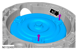
  1. NOTICE: The torque converter is heavy. Be careful not to drop it or damage will result.

    NOTICE: Only thread the bolts 6 to 8 turns or do not exceed 12 mm (0.472 in) into the torque converter. If the bolts are threaded too far, damage to the torque converter clutch surface can occur causing torque converter failure.

  1. NOTICE: Do not use water-based cleaners or mineral spirits to clean or flush the torque converter or transmission damage will occur. Use only clean transmission fluid designated for the transmission and torque converter being serviced.

    Clean and inspect the torque converter for damage.
    1. Inspect the sealing surface for a groove worn from the seal. Install a new torque converter if necessary.
    1. A new or remanufactured torque converter must be installed if one or more of the following statements is true:
      • A torque converter malfunction has been determined based on complete diagnostic procedures.
      • The torque converter stud or studs, impeller hub or bushing are damaged.
      • The torque converter exhibits external discoloration (due to overheating).
      • There is evidence of transmission assembly or fluid contamination due to the following transmission or converter failure modes.
        • Major metallic failure
        • Multiple clutch plates or band failures
        • Sufficient component wear which results in metallic contamination
        • Water or antifreeze contamination
    1. If none of the above conditions are present, continue with the following fluid inspection.
    1. Pour a small amount of transmission fluid from the torque converter onto an absorbent white tissue or through a paper filter.
    1. Examine the fluid for contaminants. The fluid must be free of metallic contaminants.
    1. NOTICE: Do not use water-based cleaners or mineral spirits to clean or flush the torque converter or transmission damage will occur.

      If the fluid passed inspection:
  1. NOTE: Note the location of the studbolts for assembly.

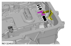
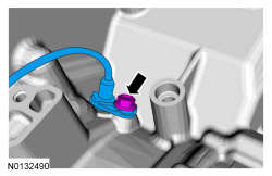
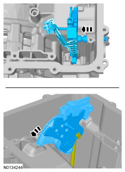
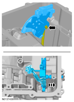
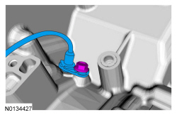
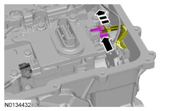
  1. Slide the TR sensor electrical connector lock tab over.
  1. NOTICE: Handle the solenoid body with care or damage to the solenoid body may occur.

  1. Clean and inspect the main control valve body for damage. If damage is found install a new main control valve body. If the main control valve body is not damaged, disassemble the main control valve body and clean it. Refer to Main Control — Overhaul .
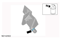
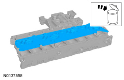
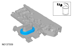
  1. Discard the specified component. Follow local disposal regulations.
  1. Check for damage or excessive wear. Visual check.
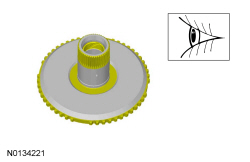
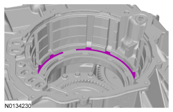
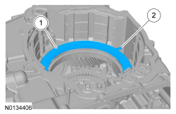
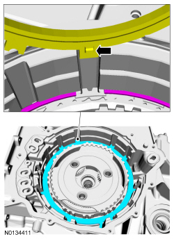
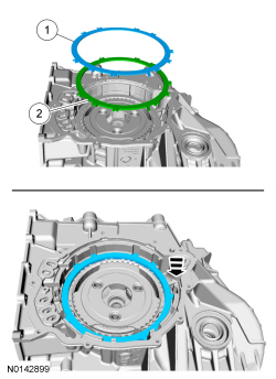
  1. NOTE: The location of the tab on the bottom pressure plate is aligned with the gap for the low OWC snap ring.

  1. Check that the bearings spin freely and do not move back and forth or side to side excessively. Check for damage or excessive wear. Visual check.
  1. Check for damage or excessive wear. Visual check.
  1. Check that the bearings spin freely and do not move back and forth or side to side excessively. Check for damage or excessive wear. Visual check.
  1. Check that the bearings spin freely and do not move back and forth or side to side excessively. Check for damage or excessive wear. Visual check.
  1. Check for damage or excessive wear. Visual check.
  1. Check for damage or excessive wear. Visual check.
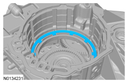
  1. NOTE: Note the orientation of the snap ring for assembly. The snap ring gap must fit around the tab of the low/reverse clutch pressure plate.

    Visual check.
  1. NOTICE: Do not clean in water or with water-based solvents. Damage to the component may occur.

    NOTE: The low OWC cannot be disassembled.

    Check for cracks and damaged splines. The internal splined section should rotate counterclockwise and lock when rotated clockwise. Visual check.
  1. Check for burned or excessively worn surface. Visual check.
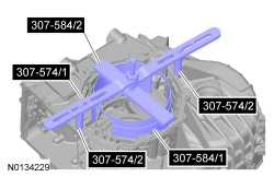
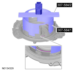
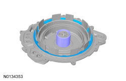
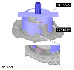
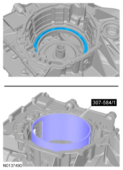
  1. NOTE: Install the Compressor, Forward/Intermediate Spring 307-584 (307-584/1 and 307-584/2) with the stepped end of the cylinder facing upward when compressing the forward clutch piston return spring.

    Compress the forward clutch piston return spring.
    Special Tool(s): Compressor, Forward/Intermediate Spring 307-584 307-584 (includes 307-584/1 and 307-584/2), Compressor, Forward Clutch Spring 307-574 (includes 307-574/1 and 307-574/2)
  1. NOTE: The Compressor, Forward/Intermediate Spring 307-584 (307-584/1 and 307-584/2) and the Compressor, Forward Clutch Spring 307-574 (307-574/1 and 307-574/2) are not shown for clarity.

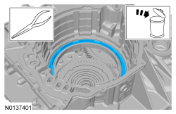
  1. Long-nosed pliers. Discard the specified component. Follow local disposal regulations.
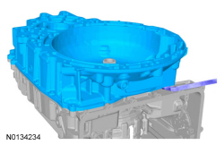
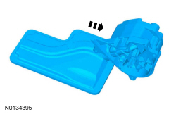
  1. NOTICE: Carefully pry on the transmission torque converter housing and the case to separate the torque converter housing from the case. Do not pry up on the silicone sealant mating surfaces, damage to the mating surfaces may occur. Carefully lift the torque converter housing off the dowel pins.

  1. NOTICE: If a differential bearing is damaged, a new bearing and bearing cup must be installed on both sides of the transfer shaft or excessive noise or transmission failure can occur.

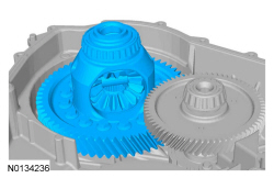
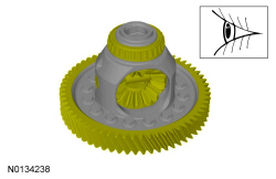
    Check the bearings for excessive wear or damage and inspect the ring gear for damage. Install new bearings or a ring gear on the differential if damage or excessive wear is found. Refer to Differential Gear Assembly . If the differential bearings are replaced the bearing races in the transmission case and the torque converter housing must also be replaced. Refer to Transaxle Case and Torque Converter Housing . If the differential ring gear is replaced, the transfer shaft must also be replaced. Refer to Transfer Shaft and Gear . Visual check.
  1. NOTICE: If a transfer shaft bearing is damaged, a new bearing and bearing cup must be installed on both sides of the transfer shaft or excessive noise or transmission failure can occur.

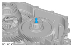
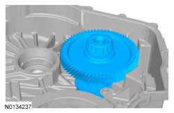
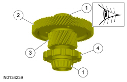
    Check the bearings for excessive wear or damage and inspect the park pawl wheel, transfer shaft and transfer shaft input gear for damage. Install new bearings, park pawl wheel, transfer shaft or transfer shaft input gear if damage or excessive wear is found. Refer to Transfer Shaft and Gear . If the transfer shaft bearings are replaced the bearing races in the transmission case and the torque converter housing case must also be replaced. Refer to Transaxle Case and Torque Converter Housing . If the transfer shaft is replaced, the differential ring gear must also be replaced. Refer to Differential Gear Assembly . Visual check.
    1. Bearings
    1. Transfer shaft input gear
    1. Transfer shaft
    1. Park pawl wheel
  1. Discard the specified component. Follow local disposal regulations.
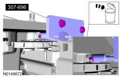
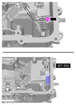
  1. Special tool(s): Remover, TRS Retaining Pin 307-696.
  1. Discard the specified component. Follow local disposal regulations.
  1. NOTICE: If the transfer shaft bearing cup is damaged, a new bearing and bearing cup must be installed on both sides of the transfer shaft or excessive noise or transmission failure can occur.

    Check the transmission case side transfer shaft bearing cup for damage. If the transmission case side transfer shaft bearing cup is damaged, install a new bearing cup. Refer to Transaxle Case . If a new bearing cup is installed in the transmission case, install a new transfer shaft bearing cup in the torque converter housing. Refer to Torque Converter Housing . Install new bearings on the transfer shaft. Refer to Transfer Shaft and Gear . Visual check.
  1. Discard the specified component. Follow local disposal regulations.
  1. NOTICE: If the differential bearing cup is damaged, a new bearing and bearing cup must be installed on both sides of the differential or excessive noise or transmission failure can occur.

    Check the transmission case side differential bearing cup for damage. If the transmission case side differential bearing cup is damaged, install a new bearing cup. Refer to Transaxle Case . If a new bearing cup is installed in the transmission case, install a new differential bearing cup in the torque converter housing. Refer to Torque Converter Housing . If a new bearing cup was installed, the differential bearings must also be replaced. Refer to Differential Gear Assembly . Visual check.
  1. NOTE: Note the orientation of the fluid filter to the fluid pump.

    Discard the specified component. Follow local disposal regulations.
    1. Pull the filter out of the bore of the fluid pump.
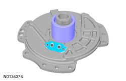
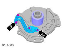
    1. If the filter seal did not come off with the filter, remove the seal from the pump.
  1. Clean and inspect the components of the pump assembly for wear or damage. Inspect the fluid drained from the pump for excessive metal or foreign material. If excessive wear, damage or excessive metal is found, replace the fluid pump as an assembly.
  1. Check the pump chain and sprocket assembly for damage or wear. Visual check.
  1. NOTICE: If the transfer shaft bearing cup is damaged, a new bearing and bearing cup must be installed on both sides of the transfer shaft or excessive noise or transmission failure can occur.

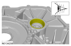
    Check the torque converter housing side transfer shaft bearing cup for damage. If the torque converter housing side transfer shaft bearing cup is damaged, install a new bearing cup. Refer to Torque Converter Housing . If a new bearing cup is installed in the torque converter housing, install a new transfer shaft bearing cup in the transmission case. Refer to Transaxle Case . Install new bearings on the transfer shaft. Refer to Transfer Shaft and Gear . Visual check.

FWD vehicles

  1. Discard the specified component. Follow local disposal regulations.

All vehicles

  1. NOTICE: If the differential bearing cup is damaged, a new bearing and bearing cup must be installed on both sides of the differential or excessive noise or transmission failure can occur.

    Check the torque converter housing side differential bearing cup for damage. If the torque converter housing side differential bearing cup is damaged, install a new bearing cup. Refer to Torque Converter Housing . If a new bearing cup is installed in the torque converter housing, install a new differential bearing cup in the transmission case. Refer to Transaxle Case . If a new bearing cup was installed, the differential bearings must also be replaced. Refer to Differential Gear Assembly . Visual check.
  1. Discard the specified component. Follow local disposal regulations.
    General Equipment: Dent Puller.
  1. Clean and inspect the transmission case and torque converter housing for damage and install a new transmission case or torque converter housing if necessary. If a new transmission case or torque converter housing is installed, refer to Transaxle Case for bearing cup installation and Torque Converter Housing for torque converter housing bearing cup installation and differential/transfer gear bearing shim measurement.
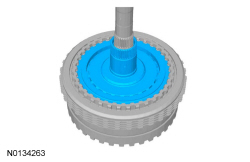
  1. Compress the overdrive piston return spring.
    Special Tool(s): Compressor, Overdrive Clutch, Balance Piston and Direct Clutch 307-589 (307-589/1), Compressor, Forward/Intermediate Spring 307-584 (307-584/2)
    General Equipment: Shop Press
  1. Discard the specified component. Follow local disposal regulations.
  1. Install the No. 1 thrust bearing on the overdrive/direct clutch assembly.
    Shop Supplies: Petroleum Jelly.
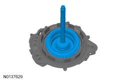
  1. Install the overdrive/direct clutch assembly in the rear cover.
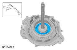
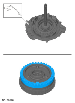
  1. Air Blow Gun.
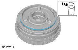
  1. Discard the specified component. Follow local disposal regulations.
  1. Discard the specified component. Follow local disposal regulations.
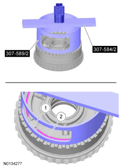
  1. NOTICE: Only compress the direct clutch piston return spring far enough to take the tension from the direct clutch cylinder off the snap ring. If the piston is compressed too far, the piston alignment tab may be broken off.

    Special Tool(s): Compressor, Overdrive Clutch, Balance Piston and Direct Clutch 307-589 (307-589/2), Compressor, Forward/Intermediate Spring 307-584 (307-584/2)
    General Equipment: Shop Press
    1. Do not contact the overdrive/direct clutch hub and shaft assembly with the direct clutch cylinder.
    1. Remove the snap ring.
  1. Install the No. 1 thrust bearing on the overdrive/direct clutch assembly.
    Shop Supplies: Petroleum Jelly.
  1. Install the overdrive/direct clutch assembly in the rear cover.
  1. Apply 483 kPa (70.05 psi) of air pressure. Air Blow Gun.
  1. Discard the specified component. Follow local disposal regulations.
  1. Discard the specified component. Follow local disposal regulations.
  1. Discard the specified component. Follow local disposal regulations.
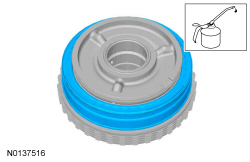
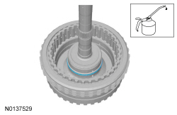
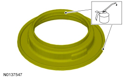
  1. Apply the specified lubricant to the specified component.
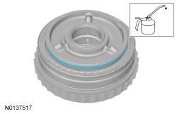
  1. Apply the specified lubricant to the specified component.
    Shop Supplies: Petroleum Jelly.
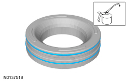
  1. Apply the specified lubricant to the specified component.
    Shop Supplies: Petroleum Jelly.
  1. Apply the specified lubricant to the specified component.
    Shop Supplies: Petroleum Jelly.
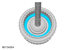
  1. NOTICE: Only compress the direct clutch piston return spring far enough to install the direct clutch cylinder snap ring. If the piston is compressed too far, the piston alignment tab may be broken off.

    NOTE: Align the tab on the direct clutch cylinder with the slot on the overdrive/direct clutch hub and shaft assembly.

    Special Tool(s): Compressor, Overdrive Clutch, Balance Piston and Direct Clutch 307-589 (307-589/2), Compressor, Forward/Intermediate Spring 307-584 (307-584/2)
    General Equipment: Shop Press
    1. Do not contact the overdrive/direct clutch hub and shaft assembly with the direct clutch cylinder.
    1. Install the snap ring.
  1. Apply the specified lubricant to the specified component.
    Shop Supplies: Petroleum Jelly.
  1. Apply the specified lubricant to the specified component.
    Shop Supplies: Petroleum Jelly.
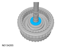
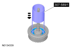
  1. NOTE: Push the overdrive clutch piston in the cylinder by hand using the Compressor, Overdrive Clutch, Balance Piston and Direct Clutch 307-589/1.

    Special Tool(s): Compressor, Overdrive Clutch, Balance Piston and Direct Clutch 307-589 (307-589/1)
  1. NOTE: Install the overdrive clutch piston return spring so that the holes are facing upward.

  1. Apply the specified lubricant to the specified component.
    Shop Supplies: Petroleum Jelly.
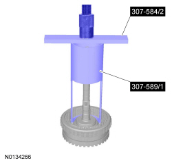
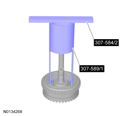
  1. Compress the overdrive clutch piston return spring.
    Special Tool(s): Compressor, Overdrive Clutch, Balance Piston and Direct Clutch 307-589 (307-589/1), Compressor, Forward/Intermediate Spring 307-584 (307-584/2)
    General Equipment: Shop Press
  1. Apply the specified lubricant to the specified component.
  1. Special Tool(s): Compressor, Forward/Intermediate Spring 307-584 (307-584/1 and 307-584/2)
    General Equipment: Shop Press
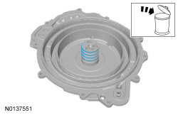
  1. Discard the specified component. Follow local disposal regulations.
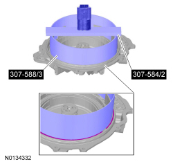
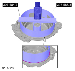
  1. Special Tool(s): Compressor, Forward/Intermediate Spring 307-584 (307-584/2), Reverse Clutch Piston and Retaining Ring Set 307-588 (307-588/3)
    General Equipment: Shop Press
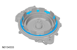
  1. Discard the specified component. Follow local disposal regulations.
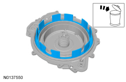
  1. Discard the specified component. Follow local disposal regulations.
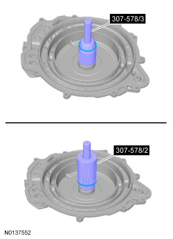
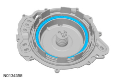
  1. Install new Teflon® seals. Adjust the Input Shaft Support Seal Installer (Back Plate, Multiple Rings) 307-578/3 and repeat step to install the other 3 seals.
    Special Tool(s): Input Shaft Support Seal Installer (Back Plate, Multiple Rings) 307-578 (307-578/2, 307-578/3)
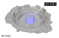
  1. Size the 4 Teflon® seals.
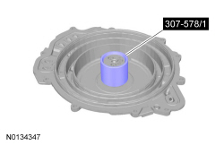
    Special Tool(s): Input Shaft Support Seal Installer (Back Plate, Multiple Rings) 307-578 (307-578/1)
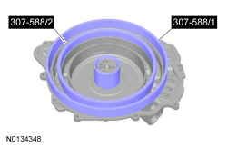
  1. Special Tool(s): Reverse Clutch Piston and Retaining Ring Set 307-588 (307-588/1 and 307-588/2).
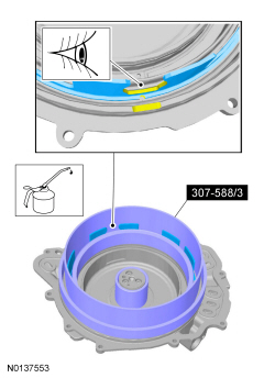
  1. Align the piston bleed hole with the indentation in the cover and push the piston in the cylinder using the Reverse Clutch Piston and Retaining Ring Set 307-588/3. Apply the specified lubricant to the specified component. Visual check.
    Shop Supplies: Petroleum Jelly.
    Special Tool(s): Reverse Clutch Piston and Retaining Ring Set 307-588 (307-588/3)
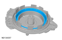
  1. NOTE: Install the low/reverse piston return spring with the tabs facing down.

  1. NOTE: Make sure the snap ring is fully seated in the groove before releasing the pressure on the return spring.

    Special Tool(s): Compressor, Forward/Intermediate Spring 307-584 (307-584/2) and the Reverse Clutch Piston and Retaining Ring Set (307-588) 307-588/3.
    General Equipment: Shop Press
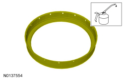
  1. Apply the specified lubricant to the specified component.
    Shop Supplies: Petroleum Jelly.
  1. NOTE: Make sure the snap ring is fully seated in the groove before releasing the pressure on the return spring.

    Special Tool(s): Compressor, Forward/Intermediate Spring 307-584
  1. Special Tool(s): Input Shaft Support Seal Installer (Back Plate, Multiple Rings) 307-578 (307-578/1)
  1. Apply the specified lubricant to the specified component.
  1. Discard the specified component. Follow local disposal regulations.
  1. Discard the specified component. Follow local disposal regulations.
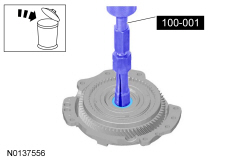
    Special Tool(s): Slide Hammer 100-001 (T50T-100-A), Collet, 7/8 Inch to 1 Inch 303-D020 (D80L-100-R)
  1. Discard the specified component. Follow local disposal regulations.
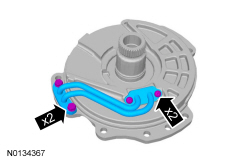
  1. NOTE: Note the location of the Torx® head and the hex head bolts for assembly.

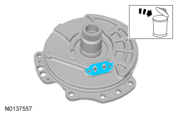
  1. Discard the specified component. Follow local disposal regulations.
  1. Clean and inspect the stator support assembly for damage and install new, if necessary.
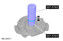
  1. Special Tool(s): Support Solid Seal Installer (Single Seal) 307-579 (307-579/2 and 307-579/3)
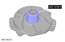
  1. Special Tool(s): Support Solid Seal Installer (Single Seal) 307-579 (307-579/1)
  1. NOTE: Install the Torx® and the hex bolts in the correct locations as noted during disassembly.

    Hand tighten.
  1. Special Tool(s): Support Seal Installer 307-585.
  1. Special Tool(s): Support Seal Installer 307-585.
  1. Remove.
    Special Tool(s): Support Solid Seal Installer (Single Seal) 307-579 (307-579/1)
  1. NOTICE: The solenoid body should be handled with care or damage to the solenoid body may occur.

    NOTICE: Do not handle the solenoid body in the leadframe area or by the screens of the solenoid body filter or damage to the solenoid body may occur.

    NOTICE: Use care not to break the alignment tabs when installing the solenoid body filter. Damage to the transmission will occur if the solenoid body is not correctly aligned.

    Pull straight up from the alignment tabs. Discard the specified component. Follow local disposal regulations.
  1. Discard the specified component. Follow local disposal regulations.
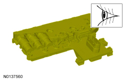
  1. Check for damage. Visual check.
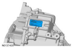
  1. If replacing the solenoid body, install the replacement service tag on the transmission case over the current solenoid body strategy tag.
  1. NOTICE: Do not handle the solenoid body in the leadframe area or by the screens of the solenoid body filter or damage to the solenoid body may occur.

    NOTICE: Use care not to break the alignment tabs when installing the solenoid body filter. Damage to the transmission will occur if the solenoid body is not correctly aligned.

    NOTICE: Make sure that the filter passage areas are clean of foreign material before installing the filter. Damage to the transmission will occur if the filter passages are not clean.

    Push filter straight down onto the alignment tabs.
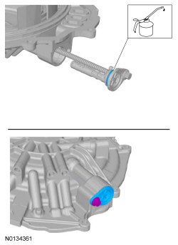
  1. Apply the specified lubricant to the specified component.
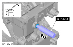
    Special Tool(s): Manual Lever Seal Installer 307-581
    Shop Supplies: Petroleum Jelly.
  1. Special Tool(s): Manual Lever Seal Installer 307-581
  1. Apply the specified lubricant to the specified component.
  1. Special Tool(s): Converter Seal Installer 307-575
  1. NOTICE: Support the torque converter housing using blocks of wood, or damage to the torque converter housing may occur.

    Special Tool(s): Converter Seal Installer 307-575

FWD vehicles

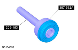
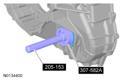
  1. Special Tool(s): Handle 205-153 (T80T-4000-W), Installer, Cover Axle Seal 307-582A
  1. NOTICE: Support the torque converter housing using blocks of wood or damage to the torque converter housing may occur.

    Special Tool(s): Handle 205-153 (T80T-4000-W), Installer, Cover Axle Seal 307-582A

All vehicles

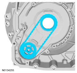
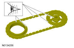
  1. NOTE: The dot on the pump sprocket is installed facing upward.

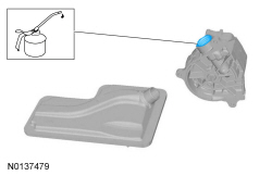
  1. Flush the pump with clean transmission fluid. Rotate the pump shaft by hand to clean the old transmission fluid out of the pump.
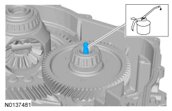
  1. Apply the specified lubricant to the specified component.
  1. NOTE: Install the filter in the correct orientation as noted in removal.

  1. NOTE: Be sure that the pump drive chain is correctly engaged on both sprockets.

  1. Apply the specified lubricant to the specified component.
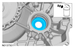
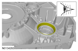
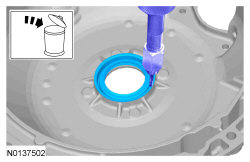
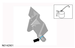
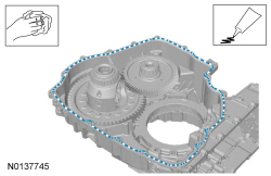
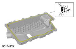
  1. Clean the specified component with the specified material. Apply the substance from the specified tube.
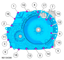
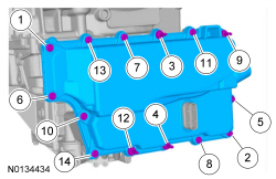
  1. NOTE: Hand tighten the bolts only.

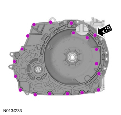
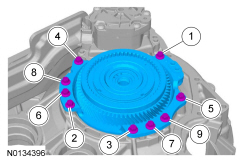
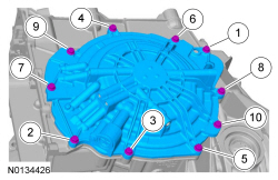
  1. NOTE: The studbolts are 1 and 16 in the tightening sequence.

  1. Special Tool(s): Handle 205-153 (T80T-4000-W), Installer, Cover Axle Seal 307-582A
  1. Special Tool(s): Handle 205-153 (T80T-4000-W), Installer, Cover Axle Seal 307-582A
  1. Apply the specified lubricant to the specified component.
    Shop Supplies: Petroleum Jelly.
  1. NOTE: Install the Compressor, Forward/Intermediate Spring 307-584/1 with the stepped end of the cylinder facing downward when pushing the forward clutch piston into the bore.

    Special Tool(s): Compressor, Forward/Intermediate Spring 307-584 (307-584/1)
  1. NOTE: Install the Compressor, Forward/Intermediate Spring with the stepped end of the cylinder facing upward when compressing the forward clutch piston return spring.

  1. NOTE: Install the Forward/Overdrive Spring Compressor with the stepped end of the cylinder facing upward when compressing the forward clutch piston return spring.

    NOTE: Before compressing the forward clutch piston return spring, make sure the spring is centered.

    Compress the forward clutch piston return spring.
    Special Tool(s): Compressor, Forward Clutch Spring 307-574 (307-574/1 and 307-574/2), Compressor, Forward/Intermediate Spring 307-584 (includes 307-584/1 and 307-584/2)
  1. NOTE: The Compressor, Forward Clutch Spring and the Compressor, Forward/Intermediate Spring not shown for clarity.

    NOTE: The snap ring gap should be at the top of the transmission case.

  1. Install the forward clutch wave spring.
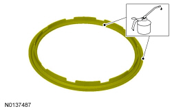
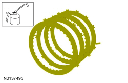
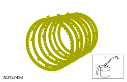
  1. Apply the specified lubricant to the specified component.
    1. Position the forward clutch pack assembly in the case.
    1. Make sure the alignment tab on the clutch pack is positioned in the correct location.
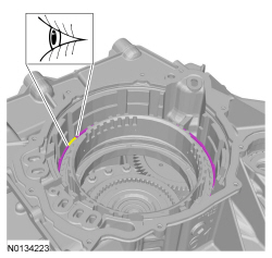
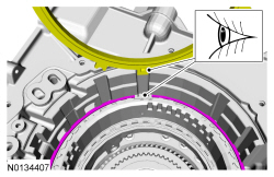
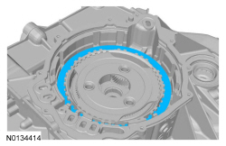
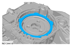
  1. NOTE: The low OWC snap ring gap must be positioned as shown so that the low/reverse clutch pressure plate tab fits into the gap when it is installed later in this procedure.

    Visual check.
  1. Compare the position of the low OWC snap ring gap with the tab on the low/reverse clutch pressure plate to be sure that the gap is in the right position. Visual check.
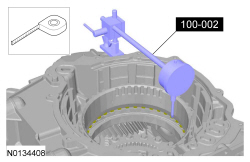
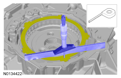
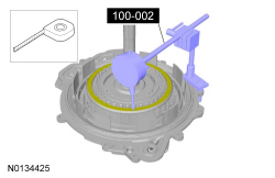
  1. Rest the plunger on a top friction disc tab.
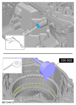
    Special Tool(s): Dial Indicator Gauge with Holding Fixture 100-002 (TOOL-4201-C)
  1. Apply 483 kPa (70 psi) of air pressure to the forward clutch piston port while recording the clutch pack clearance on the Dial Indicator. The clearance should be between 0.85 mm (0.033 in) and 2.41 mm (0.094 in). If the clearance is out of range, check the forward clutch pack and low OWC for correct installation. If the forward clutch pack and low OWC is correctly installed, install a new forward clutch pack. Air Blow Gun. Measure the length or distance.
    Special Tool(s): Dial Indicator Gauge with Holding Fixture 100-002 (TOOL-4201-C)
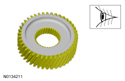
  1. NOTE: The groove on the center sun gear is installed facing up.

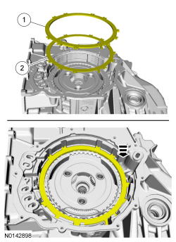
  1. NOTICE: Failure to align the tab on the bottom of the low/reverse pressure plate with the gap in the low OWC snap ring may result in damage to the transmission.

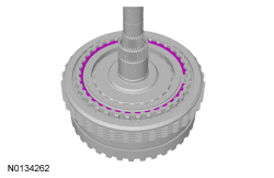
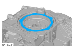
    1. Make sure the tab on the bottom of the pressure plate fits in the gap of the low OWC snap ring.
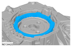
    1. Install the low/reverse clutch pressure plate.
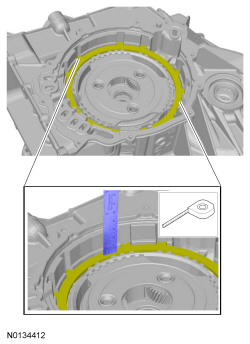
  1. Measure the depth of the low/reverse clutch pressure plate where the tab fits into the gap of the low OWC snap ring and directly across from it. If the pressure plate is seated correctly, the depth should be the same. If the depths are different, rotate the snap ring so that the gap fits around the tab on the pressure plate. Measure the length or distance.
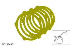
  1. Apply the specified lubricant to the specified component.
  1. Install the low/reverse clutch.
  1. NOTICE: The low/reverse clutch wave spring and pressure plate are temporarily reversely installed to measure the low/reverse clutch clearance.

    Temporarily install the low/reverse clutch wave spring and pressure plate with the pressure plate on top of the wave spring.
    1. Pressure plate
    1. Wave spring
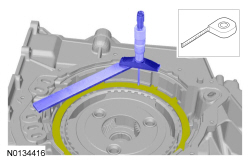
  1. Using a straightedge and the Depth Micrometer 303-D075 (D92P-4201-A), measure and record as measurement A, the distance from the transmission case deck surface to the low/reverse pressure plate. Measure the length or distance.
  1. Using the same straightedge and the Depth Micrometer 303-D075 (D92P-4201-A), measure and record as measurement B, the distance from the low/reverse clutch piston to the cover assembly deck surface. Measure the length or distance.
  1. Subtract measurement B from measurement A and add 1.6 mm (0.062 in), to compensate for the thickness of the gasket, to get the low/reverse clutch clearance. The clearance should be between 0.83 mm (0.032 in) and 2.43 mm (0.095 in). If the clearance is out of range, check the low/reverse clutch pack for correct installation. If the low/reverse clutch pack is correctly installed, install a new low/reverse clutch pack.

    Description Reading
    Measurement A  
    Measurement B  
    Subtract measurement B from measurement A and add 1.6 mm (0.062 in) to get the low/reverse clutch clearance.  

  1. NOTE: When the low/reverse clutch is correctly installed, the wave spring is on top.

    1. Wave spring
    1. Pressure plate
  1. Install the intermediate clutch pressure plate.
  1. Apply the specified lubricant to the specified component.
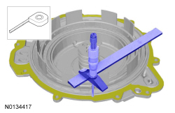
  1. Using a straightedge and the Depth Micrometer 303-D075 (D92P-4201-A), measure and record as measurement A, the distance from the transmission case deck surface to a low point on the intermediate clutch wave spring. Measure the length or distance.
  1. Using the straightedge and the Depth Micrometer 303-D075 (D92P-4201-A), measure and record as measurement B, the distance from the intermediate clutch piston to the cover assembly deck surface. Measure the length or distance.
  1. Subtract measurement B from measurement A and add 1.6 mm (0.062 in), to compensate for the thickness of the gasket, to get the intermediate clutch clearance. The clearance should be between 0.99 mm (0.038 in) and 2.56 mm (0.1 in). If the clearance is out of range, check the intermediate clutch pack for correct installation. If the intermediate clutch pack is correctly installed, install a new intermediate clutch pack.

    Description Reading
    Measurement A  
    Measurement B  
    Subtract measurement B from measurement A and add 1.6 mm (0.062 in) to get the intermediate clutch clearance.  

  1. Install the No. 1 thrust bearing on the overdrive/direct clutch assembly.
    Shop Supplies: Petroleum Jelly.
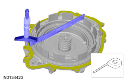
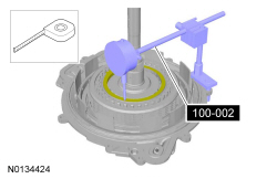
  1. Position the overdrive/direct clutch assembly in the cover assembly, install the Dial Indicator Gauge with Holding Fixture 100-002 (TOOL-4201-C) plunger on the overdrive clutch pressure plate. Apply 483 kPa (70 psi) of air pressure to the overdrive clutch piston port while recording the clutch pack clearance on the Dial Indicator. The clearance should be between 1.13 mm (0.044 in) and 2.28 mm (0.089 in). If the clearance is out of range, check the overdrive clutch pack for correct installation. If the overdrive clutch pack is correctly installed, install a new overdrive clutch pack. Measure the length or distance.
  1. Position the Dial Indicator Gauge with Holding Fixture 100-002 (TOOL-4201-C) on the direct clutch pressure plate. Apply 483 kPa (70 psi) of air pressure to the direct clutch piston port while recording the clutch pack clearance on the Dial Indicator. The clearance should be between 0.98 mm (0.038 in) and 2.34 mm (0.092 in). If the clearance is out of range, check the direct clutch pack for correct installation. If the direct clutch pack is correctly installed, install a new direct clutch pack. Measure the length or distance.
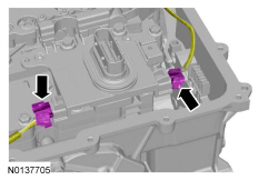
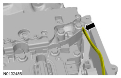
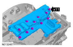
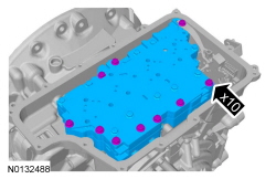
  1. NOTICE: Be careful not to pinch the TSS , OSS or TR sensor wiring harnesses under the valve body, or damage to the wiring harness or connectors may occur.

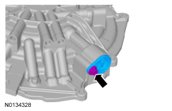
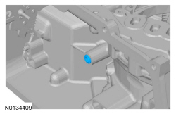
    NOTE: Make sure that the manual pin (part of the TR sensor) is correctly installed in the manual valve.

    1. Manual pin
    1. Manual valve
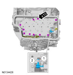
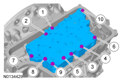
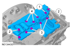
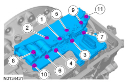
  1. NOTICE: Make sure not to pinch the TSS , OSS or TR sensor wiring harnesses behind the solenoid body when positioning the solenoid body in place.

    Hand-tighten only.
    1. 42 mm (1.653 in) bolt
    1. 63 mm (2.48 in) bolts
    1. 80 mm (3.149 in) bolts
    1. 95 mm (3.74 in) bolts
  1. Connect the TR sensor electrical connector and slide the lock tab to the LOCK position.
  1. Check for damage. Visual check.
  1. NOTE: Install the studbolts in the correct locations as noted during disassembly.

  1. NOTICE: Only thread the bolts 6 to 8 turns or do not exceed 12 mm (0.472 in) in the torque converter. If the bolts are threaded too far, damage to the torque converter clutch surface can occur, causing torque converter failure.

    Install two 10 mm x 1.50 bolts into the torque converter 6 to 8 turns to assist in handling the torque converter and install the torque converter in the transmission.
  1. Special Tool(s): Retainer, Torque Converter 307-346