SECTION 211-05: Steering Column Switches
| 2014 Flex Workshop Manual
|
DIAGNOSIS AND TESTING
| Procedure revision date: 11/08/2012
|
Steering Column Switches
DTC Charts
Diagnostic Overview
Diagnostics in this manual assume a certain skill level and knowledge of Ford-specific diagnostic practices. Refer to Diagnostic Methods in
Section 100-00
for information about these practices.
Steering Column Control Module (SCCM) DTC Chart
NOTE:
For adjustable pedal system DTCs, refer to Diagnosis and Testing in
Section 206-06
.
| DTC
| Description
| Action
|
|---|
| B1007:09
| High-Beam Headlamp Switch: Component Failure
| REFER to
Section 417-01
.
|
| B1008:09
| Wiper Mode Switch: Component Failure
| REFER to
Section 501-16
.
|
| B1051:09
| Front Washer Switch: Component Failure
| REFER to
Section 501-16
.
|
| B1052:09
| Rear Washer Switch: Component Failure
| REFER to
Section 501-16
.
|
| B10A6:09
| Main Light Switch: Component Failure
| REFER to
Section 417-01
.
|
| B10AD:02
| Rain Sensor: General Signal Failure
| REFER to
Section 501-16
.
|
| B10AD:08
| Rain Sensor: Bus Signal/Message Failure
| REFER to
Section 501-16
.
|
| B10AD:49
| Rain Sensor: Internal Electronic Failure
| REFER to
Section 501-16
.
|
| B10AD:55
| Rain Sensor: Not Configured
| CARRY OUT
using As-Built Data on the
. RETRIEVE
DTCs. If B10AD:55 returns, INSTALL a new
. REFER to
Steering Column Control Module (SCCM)
.
|
| B1124:09
| Lamp Fade Control: Component Failure
| REFER to
Section 413-00
.
|
| B1131:02
| Wiper Motor Module: General Signal Failure
| REFER to
Section 501-16
.
|
| B1131:08
| Wiper Motor Module: Bus Signal / Message Failure
| REFER to
Section 501-16
.
|
| B11D9:16
| Vehicle Battery: Circuit Below Threshold
| GO to Pinpoint Test M
.
|
| B11D9:17
| Vehicle Battery: Circuit Above Threshold
| GO to Pinpoint Test N
.
|
| B1298:09
| Steering Column Adjust Up Switch: Component Failure
| REFER to
Section 211-04
.
|
| B1299:09
| Steering Column Adjust Down Switch: Component Failure
| REFER to
Section 211-04
.
|
| B12A1:09
| Steering Column Adjust Out Switch: Component Failure
| REFER to
Section 211-04
.
|
| B12A2:09
| Steering Column Adjust In Switch: Component Failure
| REFER to
Section 211-04
.
|
| B12F7:09
| Single Wipe Switch: Component Failure
| REFER to
Section 501-16
.
|
| B1375:18
| Steering Column Tilt Motor: Circuit Current Below Threshold
| REFER to
Section 211-04
.
|
| B1375:19
| Steering Column Tilt Motor: Circuit Current Above Threshold
| REFER to
Section 211-04
.
|
| B1375:71
| Steering Column Tilt Motor: Actuator Stuck
| REFER to
Section 211-04
.
|
| B137E:18
| Steering Column Telescope Motor: Circuit Current Below Threshold
| REFER to
Section 211-04
.
|
| B137E:19
| Steering Column Telescope Motor: Circuit Current Above Threshold
| REFER to
Section 211-04
.
|
| B137E:71
| Steering Column Telescope Motor: Actuator Stuck
| REFER to
Section 211-04
.
|
| B137F:09
| Steering Wheel Left Switch Pack: Component Failure
| REFER to
Section 419-03A
or
Section 419-03B
.
|
| B137F:11
| Steering Wheel Left Switch Pack: Circuit Short to Ground
| REFER to
Section 419-03A
or
Section 419-03B
.
|
| B137F:17
| Steering Wheel Left Switch Pack: Circuit Voltage Above Threshold
| REFER to
Section 419-03A
or
Section 419-03B
.
|
| B1380:09
| Steering Wheel Right Switch Pack: Component Failure
| Refer to the appropriate section in Group
415
for the procedure.
|
| B1380:11
| Steering Wheel Right Switch Pack: Circuit Short to Ground
| Refer to the appropriate section in Group
415
for the procedure.
|
| B1380:17
| Steering Wheel Right Switch Pack: Circuit Voltage Above Threshold
| Refer to the appropriate section in Group
415
for the procedure.
|
| B1C33:11
| Steering Column Tilt Feedback Signal: Circuit Short to Ground
| REFER to
Section 211-04
.
|
| B1C33:12
| Steering Column Tilt Feedback Signal: Circuit Short to Battery
| REFER to
Section 211-04
.
|
| B1C35:11
| Steering Column Telescope Feedback Signal: Circuit Short to Ground
| REFER to
Section 211-04
.
|
| B1C35:12
| Steering Column Telescope Feedback Signal: Circuit Short to Battery
| REFER to
Section 211-04
.
|
| B1D36:09
| Turn Indicator Switch: Component Failure
| REFER to
Section 417-01
.
|
| C0051:09
| Steering Wheel Position Sensor: Component Failure
| INSTALL a new steering wheel rotation sensor. REFER to
Section 206-09
.
|
| C0051:16
| Steering Wheel Position Sensor: Circuit Voltage Below Threshold
| GO to Pinpoint Test L
.
|
| C0051:17
| Steering Wheel Position Sensor: Circuit Voltage Above Threshold
| GO to Pinpoint Test L
.
|
| U1000:00
| Solid State Driver Protection Active-Driver Disabled: No Sub Type Information
| REPAIR all other
DTCs before addressing this concern.
|
| U2100:00
| Initial Configuration Not Complete: No Sub Type Information
| CARRY OUT
using As-Built Data on the
. RETRIEVE
DTCs. If U2100:00 returns, INSTALL a new
. REFER to
Steering Column Control Module (SCCM)
.
|
| U2101:00
| Control Module Configuration Incompatible: No Sub Type Information
| This DTC sets if the steering wheel switches do not match the switch function configuration data in the
. CHECK the part numbers in Ford Catalog Advantage™ or equivalent and CONFIRM that the correct
and steering wheel control switches are installed in the vehicle. INSTALL the correct components, as necessary.
|
| U3000:49
| Control Module: Internal Electronic Failure
| INSTALL a new
. REFER to
Steering Column Control Module (SCCM)
.
|
Body Control Module (BCM) DTC Chart
NOTE:
Any push-button start system fault results in DTCs being stored in the Remote Function Actuator (RFA) module and
. Correct all
module DTCs prior to diagnosing the
DTCs listed below.
Remote Function Actuator (RFA) Module DTC Chart
Symptom Chart
Diagnostic Overview
Diagnostics in this manual assume a certain skill level and knowledge of Ford-specific diagnostic practices. Refer to Diagnostic Methods in
Section 100-00
for information about these practices.
Symptom Chart
| Condition
| Possible Sources
| Action
|
|---|
- No communication with the
| - Wiring, terminals or connectors
| |
- No communication with the
module
| - Wiring, terminals or connectors
- module
| |
- No power in all ignition switch positions — vehicles with an ignition switch
| - Refer to the Diagnostic Routine
| |
- No power in ACC — vehicles with an ignition switch
| - Refer to the Diagnostic Routine
| |
- No power in ACC — vehicles with a start/stop switch
| - Refer to the Diagnostic Routine
| |
- No power in RUN — vehicles with an ignition switch
| - Refer to the Diagnostic Routine
| |
- No power in RUN — vehicles with a start/stop switch
| - Refer to the Diagnostic Routine
| |
- No power in START — vehicles with an ignition switch
| - Refer to the Diagnostic Routine
| |
- No power in START — vehicles with a start/stop switch
| - Refer to the Diagnostic Routine
| |
- NO KEY DETECTED is displayed in the message center
| - Wiring, terminals or connectors
- key
- module antennas
| |
- STARTING SYSTEM FAULT is displayed in the message center
| - Wiring, terminals or connectors
- module
- PCM
| |
- The ignition key cannot be returned to the OFF position
| - Refer to the Diagnostic Routine
| |
- The ignition key can be turned to the OFF position when the selector lever is not in PARK
| - Refer to the Diagnostic Routine
| |
- The ignition key is hard to turn
| - Ignition lock cylinder
- Ignition key
- Ignition switch
| - REFER to the Ignition Switch — Mechanical component test in this section.
|
- The multifunction switch does not operate correctly
| | |
- The start/stop switch mode indicator is always/never illuminated
| - Refer to the Diagnostic Routine
| |
Pinpoint Tests
Pinpoint Test A: No Power in All Ignition Switch Positions — Vehicles with an Ignition Switch
Diagnostic Overview
Diagnostics in this manual assume a certain skill level and knowledge of Ford-specific diagnostic practices. Refer to Diagnostic Methods in
Section 100-00
for information about these practices.
Refer to Wiring Diagrams Cell
13
, Power Distribution/BCM for schematic and connector information.
Normal Operation and Fault Conditions
The ignition switch receives fused battery voltage from
fuse 26 (5A). In the ACC or RUN position, this voltage is sent to the
. In the START position, this voltage is sent to both the
and the PCM. When the ignition switch is cycled to the OFF/LOCK position from any other position, the
begins a monitoring cycle. The monitoring cycle checks that the voltage supplied to the
from the ignition switch through the RUN/ACC, RUN/START and START circuits is delivered correctly for each ignition switch position.
DTC Fault Trigger Conditions
| DTC
| Description
| Fault Trigger Conditions
|
|---|
| Ignition Switch: General Electric Failure
| The
continuously monitors the ignition switch position. This DTC sets if the voltage inputs to the
do not match the pre defined configurations for each ignition switch position.
|
Possible Sources
- Wiring, terminals or connectors
- Fuse
- Ignition switch
Visual Inspection and Diagnostic Pre-checks
- Inspect for damage, corrosion or loose connections.
- Make sure the battery and battery cables are OK.
- Make sure the 100A high current fuse is OK.
- Make sure
fuse 26 (5A) is OK.
PINPOINT TEST A: NO POWER IN ALL IGNITION SWITCH POSITIONS — VEHICLES WITH AN IGNITION SWITCH
| Test Step
| Result / Action to Take
|
|---|
|
A1 CHECK THE IGNITION SWITCH
|
|
| Yes
GO to
A2
.
No
INSTALL a new ignition switch. REFER to
Ignition Switch
.
|
|
A2 CHECK THE VEHICLE BATTERY
|
|
- Carry out the Battery Condition Test. REFER to
Section 414-01
.
- Is the battery OK?
| Yes
GO to
A3
.
No
CORRECT the battery condition and VERIFY correct charging operation.
|
|
A3 CHECK FOR POWER TO THE IGNITION SWITCH
|
|
- Measure the
voltage
between:
| Positive Lead
| Negative Lead
| | Pin
| Circuit
| Pin
| Circuit
| | C250-4
| SBP26 (YE/RD)
| —
| Ground
|
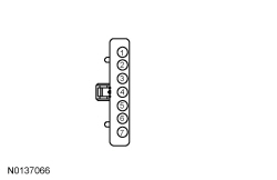 - Is the voltage greater than 11 volts?
| Yes
GO to
A5
.
No
VERIFY
fuse 26 (5A) is OK. If OK, GO to
A4
. If not OK, REFER to the Wiring Diagrams manual to identify the possible cause of the circuit short.
|
|
A4 CHECK FOR POWER TO BCM FUSE 26 (5A)
|
|
- Measure the
voltage
between:
| Positive Lead
| Negative Lead
| | Pin
| Circuit
| Pin
| Circuit
| | Fuse 26 (5A)-Input cavity
| SBF16 (RD)
| —
| Ground
|
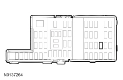 - Is the voltage greater than 11 volts?
| Yes
REPAIR circuit SBP26 (YE/RD).
No
VERIFY 100A high current fuse is OK. If OK, REPAIR the
voltage supply circuit. If not OK, REFER to the Wiring Diagrams manual to identify the possible cause of the circuit short.
|
|
A5 CHECK FOR CORRECT BCM OPERATION
|
|
- Disconnect and inspect all
connectors.
- Repair:
- corrosion (install new connector or terminals - clean module pins)
- damaged or bent pins - install new terminals/pins
- pushed-out pins - install new pins as necessary
- Reconnect the
connectors and all previously disconnected exterior system connectors. Make sure they seat and latch correctly.
- Operate the system and determine if the concern is still present.
- Is the concern still present?
| Yes
CHECK
for any applicable TSBs. If a TSB exists for this concern, DISCONTINUE this test and FOLLOW TSB instructions. If no TSBs address this concern, INSTALL a new
. REFER to
Section 419-10
.
No
The system is operating correctly at this time. The concern may have been caused by module connections. ADDRESS the root cause of any connector or pin issues.
|
Pinpoint Test B: No Power in ACC — Vehicles With an Ignition Switch
Diagnostic Overview
Diagnostics in this manual assume a certain skill level and knowledge of Ford-specific diagnostic practices. Refer to Diagnostic Methods in
Section 100-00
for information about these practices.
Refer to Wiring Diagrams Cell
13
, Power Distribution/BCM for schematic and connector information.
Normal Operation and Fault Conditions
When in ACC mode, the
provides ground for the coil (control) side of the RUN/ACC relay located in the
. The RUN/ACC relay coil receives voltage from
fuse 10 (10A). The RUN/ACC relay is serviced with the
. The
also provides a ground circuit for the coil side of the accessory delay relay located in the
. The accessory delay relay can be serviced separately from the
.
Possible Sources
- Wiring, terminals or connectors
- Fuse
- RUN/ACC relay (part of the
)
- Accessory delay relay
Visual Inspection and Diagnostic Pre-checks
- Make sure
fuse 10 (10A) is OK.
PINPOINT TEST B: NO POWER IN ACC — VEHICLES WITH AN IGNITION SWITCH
| Test Step
| Result / Action to Take
|
|---|
|
B1 CHECK FOR ACC VOLTAGE AT THE BCM
|
|
- Disconnect:
C2280B .
- Ignition In ACC.
- Measure the
voltage
between:
| Positive Lead
| Negative Lead
| | Pin
| Circuit
| Pin
| Circuit
| | C2280B-35
| CDC33 (VT)
| —
| Ground
|
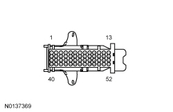 - Is the voltage greater than 11 volts?
| Yes
GO to
B3
.
No
GO to
B2
.
|
|
B2 CHECK THE IGNITION ACC CIRCUIT FOR AN OPEN
|
|
- Ignition OFF.
- Disconnect: Ignition Switch C250 .
- Measure the
resistance
between:
| Positive Lead
| Negative Lead
| | Pin
| Circuit
| Pin
| Circuit
| | C2280B-35
| CDC33 (VT)
| C250-6
| CDC33 (VT)
|
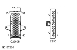 - Is the resistance less than 3 ohms?
| Yes
INSTALL a new ignition switch. REFER to
Ignition Switch
.
No
REPAIR the circuit.
|
|
B3 CHECK FOR POWER TO THE RUN/ACC RELAY
|
|
- Ignition OFF.
- Disconnect:
fuse 10 (10A) .
- Measure the
voltage
between:
| Positive Lead
| Negative Lead
| | Pin
| Circuit
| Pin
| Circuit
| | Fuse 10 (10A)-Input cavity
| —
| —
| Ground
|
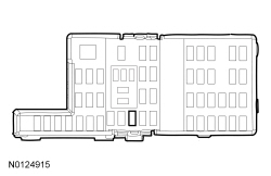 - Is the voltage greater than 11 volts?
| Yes
VERIFY
fuse 10 (10A) is OK. If OK, GO to
B4
. If not OK, REFER to the Wiring Diagrams manual to identify the possible cause of the circuit short.
No
GO to
B5
.
|
|
B4 CHECK THE ACCESSORY DELAY RELAY
|
|
| Yes
GO to
B5
.
No
INSTALL a new accessory delay relay.
|
|
B5 CHECK FOR CORRECT BCM OPERATION
|
|
- Disconnect and inspect all
connectors.
- Repair:
- corrosion (install new connector or terminals - clean module pins)
- damaged or bent pins - install new terminals/pins
- pushed-out pins - install new pins as necessary
- Reconnect the
connectors and all previously disconnected exterior system connectors. Make sure they seat and latch correctly.
- Install
fuse 10 (10A).
- Operate the system and determine if the concern is still present.
- Is the concern still present?
| Yes
CHECK
for any applicable TSBs. If a TSB exists for this concern, DISCONTINUE this test and FOLLOW TSB instructions. If no TSBs address this concern, INSTALL a new
. REFER to
Section 419-10
.
No
The system is operating correctly at this time. The concern may have been caused by module connections. ADDRESS the root cause of any connector or pin issues.
|
Pinpoint Test C: No Power in RUN — Vehicles With an Ignition Switch
Diagnostic Overview
Diagnostics in this manual assume a certain skill level and knowledge of Ford-specific diagnostic practices. Refer to Diagnostic Methods in
Section 100-00
for information about these practices.
Refer to Wiring Diagrams Cell
13
, Power Distribution/BCM for schematic and connector information.
Normal Operation and Fault Conditions
When the ignition switch is turned to the RUN position, a voltage signal is sent to the
. The
then activates the RUN/START relay and the RUN/ACC relay which distribute fused voltage to various components. The
uses a
to control the RUN/START relay. The RUN/START relay receives voltage from
fuse 87 (5A). The RUN/ACC relay is serviced as part of the
.
DTC Fault Trigger Conditions
| DTC
| Description
| Fault Trigger Conditions
|
|---|
| Run/Start Control: Circuit Short to Ground or Open
| The
continuously monitors the control side of the RUN/START relay. This DTC is set if the
detects an open or a short to ground on the control circuit. When this DTC sets, the control side of the RUN/START relay is disabled via the
. Once the condition that caused the DTC to set is repaired, the
must pass a self-test in order for the DTC to clear and the system to resume normal operation.
|
Possible Sources
- Wiring, terminals or connectors
- Fuse
- RUN/START relay
- Ignition switch
Visual Inspection and Diagnostic Pre-checks
- Make sure
fuse 87 (5A) is OK.
PINPOINT TEST C: NO POWER IN RUN — VEHICLES WITH AN IGNITION SWITCH
| Test Step
| Result / Action to Take
|
|---|
|
C1 CHECK THE BCM FOR DTC
|
|
- Ignition ON.
- Using a scan tool, perform
self-test.
- Is DTC B1310:14 present?
| Yes
GO to
C4
.
No
For
DTCs, REFER to
Section 419-10
.
If no DTCs are present, GO to
C2
.
|
|
C2 CHECK FOR RUN VOLTAGE AT THE BCM
|
|
- Ignition OFF.
- Disconnect:
C2280B .
- Ignition ON.
- Measure the
voltage
between:
| Positive Lead
| Negative Lead
| | Pin
| Circuit
| Pin
| Circuit
| | C2280B-29
| CDC34 (WH/OG)
| —
| Ground
|
 - Is the voltage greater than 11 volts?
| Yes
GO to
C4
.
No
GO to
C3
.
|
|
C3 CHECK THE IGNITION RUN CIRCUIT FOR AN OPEN
|
|
- Ignition OFF.
- Disconnect: Ignition Switch C250 .
- Measure the
resistance
between:
| Positive Lead
| Negative Lead
| | Pin
| Circuit
| Pin
| Circuit
| | C2280B-29
| CDC34 (WH/OG)
| C250-1
| CDC34 (WH/OG)
|
 - Is the resistance less than 3 ohms?
| Yes
INSTALL a new ignition switch. REFER to
Ignition Switch
.
No
REPAIR the circuit.
|
|
C4 CHECK THE RUN/START RELAY
|
|
| Yes
GO to
C5
.
No
INSTALL a new RUN/START relay.
|
|
C5 CHECK THE VOLTAGE TO THE RUN/START RELAY COIL
|
|
- Measure the
voltage
between:
| Positive Lead
| Negative Lead
| | Pin
| Circuit
| Pin
| Circuit
| | RUN/START relay-2
| SBB87 (WH/RD)
| —
| Ground
|
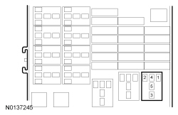 - Is the voltage greater than 11 volts?
| Yes
GO to
C6
.
No
VERIFY
fuse 87 (5A) Is OK. If OK, REPAIR the circuit. If not OK, REFER to the Wiring Diagrams manual to identify the possible cause of the circuit short.
|
|
C6 CHECK THE RUN/START RELAY CONTROL CIRCUIT FOR AN OPEN
|
|
- Ignition OFF.
- Disconnect:
C2280F .
- Measure the
resistance
between:
| Positive Lead
| Negative Lead
| | Pin
| Circuit
| Pin
| Circuit
| | RUN/START relay-1
| CDC55 (BN/VT)
| C2280F-18
| CDC55 (BN/VT)
|
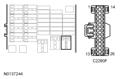 - Is the resistance less than 3 ohms?
| Yes
GO to
C7
.
No
REPAIR the circuit.
|
|
C7 CHECK THE RUN/START RELAY CONTROL CIRCUIT FOR A SHORT TO GROUND
|
|
- Measure the
resistance
between:
| Positive Lead
| Negative Lead
| | Pin
| Circuit
| Pin
| Circuit
| | C2280F-18
| CDC55 (BN/VT)
| —
| Ground
|
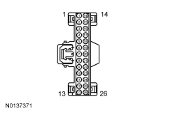 - Is the resistance greater than 10,000 ohms?
| Yes
GO to
C8
.
No
REPAIR the circuit.
|
|
C8 CHECK FOR CORRECT BCM OPERATION
|
|
- Disconnect and inspect all
connectors.
- Repair:
- corrosion (install new connector or terminals - clean module pins)
- damaged or bent pins - install new terminals/pins
- pushed-out pins - install new pins as necessary
- Reconnect the
connectors and all previously disconnected exterior system connectors. Make sure they seat and latch correctly.
- Operate the system and determine if the concern is still present.
- Is the concern still present?
| Yes
CHECK
for any applicable TSBs. If a TSB exists for this concern, DISCONTINUE this test and FOLLOW TSB instructions. If no TSBs address this concern, INSTALL a new
. REFER to
Section 419-10
.
No
The system is operating correctly at this time. The concern may have been caused by module connections. ADDRESS the root cause of any connector or pin issues.
|
Pinpoint Test D: No Power in START — Vehicles With an Ignition Switch
Diagnostic Overview
Diagnostics in this manual assume a certain skill level and knowledge of Ford-specific diagnostic practices. Refer to Diagnostic Methods in
Section 100-00
for information about these practices.
Refer to Wiring Diagrams Cell
13
, Power Distribution/BCM for schematic and connector information.
Refer to Wiring Diagrams Cell
20
, Starting System for schematic and connector information.
Normal Operation and Fault Conditions
When the ignition switch is turned to the START position, a voltage signal is sent to the
and the PCM. The
sends out a voltage signal to various modules to indicate a start event and the PCM checks various inputs and
bus messages before activating the starter motor.
Possible Sources
- Wiring, terminals or connectors
- Ignition switch
PINPOINT TEST D: Pinpoint Test D: NO POWER IN START — VEHICLES WITH AN IGNITION SWITCH
| Test Step
| Result / Action to Take
|
|---|
|
D1 CHECK THE KEY POSITION FOR START INDICATED (START_KEY) PID
|
|
- Ignition ON.
- Enter the following diagnostic mode on the scan tool: DataLogger — PCM .
- Monitor the PCM PID START_KEY.
- Momentarily turn the key to START and release it.
- Does the PID read On when the ignition is in the START position?
| Yes
REFER to
Section 303-06
.
No
GO to
D2
.
|
|
D2 CHECK FOR VOLTAGE TO THE BCM AND PCM
|
|
- Ignition OFF.
- Disconnect:
C2280B .
- Disconnect: PCM C175B (3.5L
) .
- Disconnect: PCM C1381B (3.5L
) .
- With the ignition switch in the START position, measure the
voltage
between:
| Positive Lead
| Negative Lead
| | Pin
| Circuit
| Pin
| Circuit
| | C2280B-47
| CDC35 (BU/WH)
| —
| Ground
|
 - Is the voltage greater than 11 volts?
| Yes
GO to
D4
.
No
GO to
D3
.
|
|
D3 CHECK THE IGNITION START CIRCUIT FOR AN OPEN
|
|
- Ignition OFF.
- Disconnect: Ignition Switch C250 .
- Measure the
resistance
between:
| Positive Lead
| Negative Lead
| | Pin
| Circuit
| Pin
| Circuit
| | C2280B-47
| CDC35 (BU/WH)
| C250-7
| CDC35 (BU/WH)
|
 - Is the resistance less than 3 ohms?
| Yes
INSTALL a new ignition switch. REFER to
Ignition Switch
.
No
REPAIR the circuit.
|
|
D4 CHECK FOR CORRECT BCM OPERATION
|
|
- Disconnect and inspect all
connectors.
- Repair:
- corrosion (install new connector or terminals - clean module pins)
- damaged or bent pins - install new terminals/pins
- pushed-out pins - install new pins as necessary
- Reconnect the
connectors and all previously disconnected exterior system connectors. Make sure they seat and latch correctly.
- Operate the system and determine if the concern is still present.
- Is the concern still present?
| Yes
CHECK
for any applicable TSBs. If a TSB exists for this concern, DISCONTINUE this test and FOLLOW TSB instructions. If no TSBs address this concern, INSTALL a new
. REFER to
Section 419-10
.
No
The system is operating correctly at this time. The concern may have been caused by module connections. ADDRESS the root cause of any connector or pin issues.
|
Pinpoint Test E: No Power in RUN/No Power in START - Vehicles With a Start/Stop Switch
Diagnostic Overview
Diagnostics in this manual assume a certain skill level and knowledge of Ford-specific diagnostic practices. Refer to Diagnostic Methods in
Section 100-00
for information about these practices.
Refer to Wiring Diagrams Cell
13
, Power Distribution/BCM for schematic and connector information.
Refer to Wiring Diagrams Cell
20
, Starting System for schematic and connector information.
Normal Operation and Fault Conditions
When in RUN mode, the
provides a ground for the coil (control) side of the RUN/START relay located in the
. The
monitors the RUN/START relay control circuit; a DTC sets if the circuit is shorted to ground or open. The start/stop switch provides a voltage input to the
module and PCM. The start/stop switch also provides a voltage and ground input to the
. The 3 modules exchange information over the
to determine if starting the engine is authorized. If
authorizes the starting of the engine, the PCM supplies power and ground to the starter relay.
To place the vehicle in RUN mode, locate the
key inside the vehicle and press the start/stop switch once, for at least one second, without applying the brake pedal.
To start the engine, locate the
key inside the vehicle and press the start/stop switch while the brake pedal is applied.
DTC Fault Trigger Conditions
| DTC
| Description
| Fault Trigger Conditions
|
|---|
| Run/Start Control: Circuit Short to Ground or Open
| The
continuously monitors the control side of the RUN/START relay. This DTC is set if the
detects an open or a short to ground on the control circuit. The
uses a
to control the RUN/START relay. When this DTC sets, the control side of the RUN/START relay is disabled via the
. Once the condition that caused the DTC to set is repaired, the
must pass a self-test in order for the DTC to clear and the system to resume normal operation.
|
Possible Sources
- Battery
- Fuse(s)
- Wiring, terminals or connectors
- RUN/START relay
- Start/stop switch
- Starting system
- switch (also referred to as stoplamp switch)
- system
- module or antennas
Visual Inspection and Diagnostic Pre-checks
- Make sure the battery, battery cables and battery terminals are free of corrosion and damage.
- Make sure 100A high current fuse is OK.
- Make sure
fuse 87 (5A) is OK.
- Make sure
fuse 59 (10A) is OK.
- Make sure
fuse 94 (30A) is OK.
PINPOINT TEST E: NO POWER IN RUN/NO POWER IN START — VEHICLES WITH A START/STOP SWITCH
| Test Step
| Result / Action to Take
|
|---|
|
E1 CHECK THE BCM BATTERY FEED CIRCUIT FOR AN OPEN
|
|
- Disconnect:
C2280G .
- Measure the
voltage
between:
| Positive Lead
| Negative Lead
| | Pin
| Circuit
| Pin
| Circuit
| | C2280G-1
| SBF01 (RD)
| —
| Ground
|
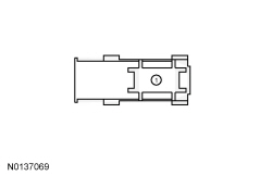 - Is the voltage greater than 11 volts?
| Yes
GO to
E2
.
No
VERIFY the 100A high current fuse is OK. If OK, REPAIR the circuit. If not OK, REFER to the Wiring Diagrams manual to identify the possible cause of the circuit short.
|
|
E2 CONFIRM THE IA KEY ALLOWS VEHICLE ENTRY
|
|
- Connect:
C2280G .
- NOTE:
Verify that the
key is not inside the vehicle before proceeding with this step.
- With the driver door locked and the
key within 1 m (3.28 ft) of the driver door, grab the driver door handle. The driver door handle is equipped with capacitive touch sensors to lock and unlock the door.
- Did the driver door unlock?
| Yes
GO to
E4
.
No
GO to
E3
.
|
|
E3 CHECK THE VEHICLE BATTERY
|
|
- Carry out the Battery Condition Test. REFER to
Section 414-01
.
- Is the battery OK?
| Yes
REFER to
Section 501-14B
to diagnose the IA concern.
No
CORRECT the battery condition and VERIFY correct charging operation.
|
|
E4 ATTEMPT VEHICLE START WHILE MONITORING MESSAGE CENTER
|
|
- With the vehicle in PARK and the
key in the vehicle, press and hold the brake pedal, then press the start/stop switch while monitoring message center messages.
- Did the engine crank?
| Yes
The fault is not present at this time. Using a scan tool, PERFORM PCM
self-test. REFER to the Powertrain Control/Emissions Diagnosis (PC/ED) manual manual to diagnose the no start concern.
No
If NO KEY DETECTED is displayed in the message center, REFER to
Section 419-01B
or
Section 419-01C
to diagnose the
module and interior antenna concern.
If STARTER SYSTEM FAULT is displayed in the message center, REFER to
Section 419-01B
or
Section 419-01C
to diagnose the
concern.
If PRESS BRAKE TO START is displayed in the message center, GO to
E12
.
If no message is displayed in the message center, GO to
E5
.
|
|
E5 CARRY OUT A RFA MODULE SELF-TEST
|
|
NOTE:
The
module is able to carry out a self-test with the ignition in the OFF mode. When the scan tool indicates "Turn the Ignition ON" or "Ignition ON", ignore this command and press or click the "continue" button.
NOTE:
module communication is indicated by the completion of the self-test.
- Enter the following diagnostic mode on the scan tool: Self Test —
Module .
- Record any
module DTCs.
- Did the
module communicate with the scan tool?
| Yes
GO to
E6
.
No
REFER to
Section 418-00
to diagnose the
module communication concern.
|
|
E6 REVIEW RFA MODULE DTC
|
|
- Refer to the results of the
module self-test.
- Are any start/stop switch DTCs and/or
communication DTCs present in the
module?
| Yes
REFER to
Section 419-10
to diagnose the
module DTCs.
No
GO to
E7
.
|
|
E7 CHECK FOR IGNITION RUN MODE
|
|
- NOTE:
The air bag warning indicator in the
illuminates and proves out only if the ignition successfully enters RUN mode.
- With the
key still in the vehicle, press and hold the brake pedal, then press the start/stop switch for at least one second while monitoring the air bag warning indicator in the
.
- Did the air bag warning indicator illuminate for at least 6 seconds and then go out?
| Yes
REFER to
Section 303-06
.
No
If other indicators in the
are illuminated, GO to
E8
.
If there is no response from the
when pressing the start/stop switch,
GO to Pinpoint Test J
.
|
|
E8 ISOLATE THE RUN/START RELAY
|
|
| Yes
GO to
E9
.
No
INSTALL a new RUN/START relay.
|
|
E9 CHECK THE RUN/START RELAY OUTPUT CIRCUIT FOR AN OPEN
|
|
- Disconnect:
C2280E .
- Measure the
resistance
between:
| Positive Lead
| Negative Lead
| | Pin
| Circuit
| Pin
| Circuit
| | RUN/START relay-5
| —
| C2280E-10
| CDC21 (GY/BN)
|
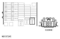 - Is the resistance less than 3 ohms?
| Yes
GO to
E10
.
No
VERIFY
fuse 94 (30A) is OK. If OK, REPAIR the circuit. If not OK, REFER to the Wiring Diagrams manual to identify the possible cause of the circuit short.
|
|
E10 CHECK FOR POWER TO THE RUN/START RELAY
|
|
- Measure the
voltage
between:
| Positive Lead
| Negative Lead
| | Pin
| Circuit
| Pin
| Circuit
| | RUN/START relay-2
| SBB87 (WH/RD)
| —
| Ground
|
 - Is the voltage greater than 11 volts?
| Yes
GO to
E11
.
No
VERIFY
fuse 87 (5A) is OK. If OK, REPAIR the circuit. If not OK, REFER to the Wiring Diagrams manual to identify the possible cause of the circuit short.
|
|
E11 CHECK THE RUN/START RELAY CONTROL CIRCUIT FOR AN OPEN
|
|
- Disconnect:
C2280F .
- Measure the
resistance
between:
| Positive Lead
| Negative Lead
| | Pin
| Circuit
| Pin
| Circuit
| | RUN/START relay-1
| CDC55 (BN/VT)
| C2280F-18
| CDC55 (BN/VT)
|
 - Is the resistance less than 3 ohms?
| Yes
GO to
E14
.
No
REPAIR the circuit.
|
|
E12 CHECK FOR POWER TO THE BRAKE PEDAL POSITION SWITCH
|
|
- Disconnect:
Switch C278 .
- Measure the
voltage
between:
| Positive Lead
| Negative Lead
| | Pin
| Circuit
| Pin
| Circuit
| | C278-1
| SBB59 (BU/RD)
| —
| Ground
|
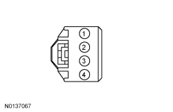 - Is the voltage greater than 11 volts?
| Yes
GO to
E13
.
No
VERIFY
fuse 59 (10A) is OK. If OK, REPAIR the circuit. If not OK, REFER to the Wiring Diagrams manual to identify the possible cause of the circuit short.
|
|
E13 CHECK THE BRAKE PEDAL POSITION SWITCH INPUT TO THE BCM FOR AN OPEN
|
|
- Disconnect:
C2280B .
- Measure the
resistance
between:
| Positive Lead
| Negative Lead
| | Pin
| Circuit
| Pin
| Circuit
| | C278-4
| CCB08 (VT/WH)
| C2280B-28
| CCB08 (VT/WH)
|
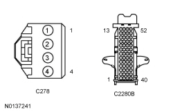 - Is the resistance less than 3 ohms?
| Yes
INSTALL a new stoplamp switch (also referred to as
switch). REFER to
Section 417-01
.
No
REPAIR the circuit.
|
|
E14 CHECK FOR CORRECT BCM OPERATION
|
|
- Disconnect and inspect all
connectors.
- Repair:
- corrosion (install new connector or terminals - clean module pins)
- damaged or bent pins - install new terminals/pins
- pushed-out pins - install new pins as necessary
- Reconnect the
connectors and all previously disconnected exterior system connectors. Make sure they seat and latch correctly.
- Operate the system and determine if the concern is still present.
- Is the concern still present?
| Yes
CHECK
for any applicable TSBs. If a TSB exists for this concern, DISCONTINUE this test and FOLLOW TSB instructions. If no TSBs address this concern, INSTALL a new
. REFER to
Section 419-10
.
No
The system is operating correctly at this time. The concern may have been caused by module connections. ADDRESS the root cause of any connector or pin issues.
|
Pinpoint Test F: No Power in ACC - Vehicles with a Start/Stop Switch
Diagnostic Overview
Diagnostics in this manual assume a certain skill level and knowledge of Ford-specific diagnostic practices. Refer to Diagnostic Methods in
Section 100-00
for information about these practices.
Refer to Wiring Diagrams Cell
13
, Power Distribution/BCM for schematic and connector information.
Normal Operation and Fault Conditions
When in ACC mode, the
provides a ground for the coil (control) side of the RUN/ACC relay located in the
. The RUN/ACC relay is serviced with the
. The
also provides a ground for the coil side of the accessory delay relay located in the
. The accessory delay relay is serviced separately from the
. When the vehicle is in ACC mode, ACCESSORY POWER ACTIVE will be displayed in the message center. To place the vehicle in ACC mode, locate the
key inside the vehicle and press the start/stop switch once without applying the brake pedal.
Possible Sources
- Fuse(s)
- Wiring, terminals or connectors
- RUN/ACC relay (part of
)
- Accessory delay relay
PINPOINT TEST F: NO POWER IN ACC — VEHICLES WITH A START/STOP SWITCH
| Test Step
| Result / Action to Take
|
|---|
|
F1 VERIFY OTHER IGNITION MODES
|
|
- With the
key in the vehicle, press the start/stop switch for at least one second without pressing the brake pedal.
- Does the vehicle enter RUN mode?
| Yes
GO to
F2
.
No
GO to Pinpoint Test E
.
|
|
F2 CHECK THE ACCESSORY DELAY RELAY
|
|
| Yes
GO to
F3
.
No
INSTALL a new accessory delay relay.
|
|
F3 VERIFY BCM FUSE 10 (10A)
|
|
- Verify
fuse 10 (10A) is OK.
- Is
fuse 10 (10A) OK?
| Yes
GO to
F4
.
No
REFER to Wiring Diagrams manual to identify the possible cause of the circuit short.
|
|
F4 CHECK FOR CORRECT BCM OPERATION
|
|
- Disconnect and inspect all
connectors.
- Repair:
- corrosion (install new connector or terminals - clean module pins)
- damaged or bent pins - install new terminals/pins
- pushed-out pins - install new pins as necessary
- Reconnect the
connectors and all previously disconnected exterior system connectors. Make sure they seat and latch correctly.
- Operate the system and determine if the concern is still present.
- Is the concern still present?
| Yes
CHECK
for any applicable TSBs. If a TSB exists for this concern, DISCONTINUE this test and FOLLOW TSB instructions. If no TSBs address this concern, INSTALL a new
. REFER to
Section 419-10
.
No
The system is operating correctly at this time. The concern may have been caused by module connections. ADDRESS the root cause of any connector or pin issues.
|
Pinpoint Test G: The Ignition Key Cannot Be Returned to the OFF Position
Diagnostic Overview
Diagnostics in this manual assume a certain skill level and knowledge of Ford-specific diagnostic practices. Refer to Diagnostic Methods in
Section 100-00
for information about these practices.
Refer to Wiring Diagrams Cell
37
, Shift Interlock for schematic and connector information.
Normal Operation and Fault Conditions
The key removal inhibit solenoid (part of the ignition switch) receives battery voltage from
fuse 26 (5A). When the selector lever is moved into the PARK position, the
(part of the selector lever) opens, interrupting a ground circuit to the key removal inhibit solenoid. The key removal inhibit solenoid deactivates and allows the ignition lock cylinder to be turned to the OFF position and the key to be removed.
Possible Sources
- Wiring, terminals or connectors
- Ignition lock cylinder
- Key removal inhibit solenoid (part of the ignition switch)
- (part of the selector lever)
PINPOINT TEST G: THE IGNITION KEY CANNOT BE RETURNED TO THE OFF POSITION
| Test Step
| Result / Action to Take
|
|---|
|
G1 CHECK FOR AN ENERGIZED KEY REMOVAL INHIBIT SOLENOID
|
|
- Remove
fuse 26 (5A).
- Attempt to turn the ignition lock cylinder to the RUN position and then back to the OFF position and remove the key.
- Can the ignition lock cylinder be turned to the OFF position and can the key be removed?
| Yes
GO to
G3
.
No
GO to
G2
.
|
|
G2 CHECK THE IGNITION SWITCH FOR MECHANICAL DAMAGE
|
|
- Remove the ignition switch. REFER to
Ignition Switch
.
- Attempt to turn the ignition lock cylinder to the OFF position and remove the ignition key.
- Does the ignition lock cylinder turn to the OFF position and can the key be removed?
| Yes
INSTALL a new ignition switch (includes key inhibit solenoid). REFER to
Ignition Switch
.
No
REFER to the mechanical symptom chart in
Section 501-14A
to diagnose the concern.
|
|
G3 CHECK THE KEY REMOVAL INHIBIT SOLENOID CIRCUIT FOR GROUND
|
|
- Select PARK.
- Disconnect: Ignition Switch C250 .
- Measure the
resistance
between:
| Positive Lead
| Negative Lead
| | Pin
| Circuit
| Pin
| Circuit
| | C250-3
| CDC41 (WH/BN)
| —
| Ground
|
 - Is the resistance to ground greater than 10,000 ohms?
| Yes
INSTALL a new ignition switch (includes key removal inhibit solenoid). REFER to
Ignition Switch
.
No
GO to
G4
.
|
|
G4 ISOLATE THE SHORT TO GROUND IN THE KEY REMOVAL INHIBIT SOLENOID CIRCUIT
|
|
- Disconnect: Brake Shift Interlock C3245 .
- Measure the
resistance
between:
| Positive Lead
| Negative Lead
| | Pin
| Circuit
| Pin
| Circuit
| | C250-3
| CDC41 (WH/BN)
| —
| Ground
|
 - Is the resistance to ground greater than 10,000 ohms?
| Yes
INSTALL a new selector lever (includes
). REFER to
Section 307-05
.
No
REPAIR the circuit.
|
Pinpoint Test H: The Ignition Key Can Be Turned to the OFF Position When the Selector Lever is Not in PARK
Diagnostic Overview
Diagnostics in this manual assume a certain skill level and knowledge of Ford-specific diagnostic practices. Refer to Diagnostic Methods in
Section 100-00
for information about these practices.
Refer to Wiring Diagrams Cell
37
, Shift Interlock for schematic and connector information.
Normal Operation and Fault Conditions
The key removal inhibit solenoid (part of the ignition switch) receives battery voltage from
fuse 26 (5A). When the selector lever is moved out of the PARK position, the
(part of the selector lever) closes, providing a ground circuit to the key removal inhibit solenoid. The key removal inhibit solenoid activates and prevents the ignition lock cylinder from being turned to the OFF position and the key from being removed.
Possible Sources
- Wiring, terminals or connectors
- Key removal inhibit solenoid (part of the ignition switch)
- (part of the selector lever)
PINPOINT TEST H: THE IGNITION KEY CAN BE TURNED TO THE OFF POSITION WHEN THE SELECTOR LEVER IS NOT IN PARK
| Test Step
| Result / Action to Take
|
|---|
|
H1 CHECK THE KEY REMOVAL INHIBIT SOLENOID GROUND CIRCUIT FOR AN OPEN
|
|
- Select PARK.
- Disconnect: Ignition Switch C250 .
- Measure the
resistance
between:
| Positive Lead
| Negative Lead
| | Pin
| Circuit
| Pin
| Circuit
| | C250-3
| CDC41 (WH/BN)
| —
| Ground
|
 - Is the resistance less than 3 ohms?
| Yes
INSTALL a new ignition switch (includes key removal inhibit solenoid). REFER to
Ignition Switch
.
No
GO to
H2
.
|
|
H2 CHECK THE KEY REMOVAL INHIBIT SOLENOID CIRCUIT FOR AN OPEN
|
|
- Disconnect: Brake Shift Interlock C3245 .
- Measure the
resistance
between:
| Positive Lead
| Negative Lead
| | Pin
| Circuit
| Pin
| Circuit
| | C3245-1
| CDC41 (WH/BN)
| C250-3
| CDC41 (WH/BN)
|
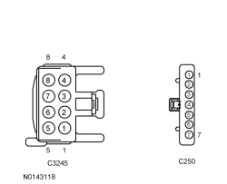 - Is the resistance less than 3 ohms?
| Yes
GO to
H3
.
No
REPAIR the circuit.
|
|
H3 CHECK THE BRAKE SHIFT INTERLOCK ACTUATOR GROUND CIRCUIT FOR AN OPEN
|
|
-
Measure the
resistance
between:
| Positive Lead
| Negative Lead
| | Pin
| Circuit
| Pin
| Circuit
| | C3245-4
| GD375 (BK/BU)
| —
| Ground
|
 - Is the resistance less than 3 ohms?
| Yes
INSTALL a new selector lever (includes
). REFER to
Section 307-05
.
No
REPAIR the circuit.
|
Pinpoint Test I: The Start-Stop Switch Mode Indicator is Always or Never Illuminated
Diagnostic Overview
Diagnostics in this manual assume a certain skill level and knowledge of Ford-specific diagnostic practices. Refer to Diagnostic Methods in
Section 100-00
for information about these practices.
Refer to Wiring Diagrams Cell
13
, Power Distribution/BCM for schematic and connector information.
Normal Operation and Fault Conditions
The
uses a
as circuit protection for the start/stop switch indicator and as an electronic switch to turn the start/stop switch indicator On and Off. The
receives fused battery voltage from
fuse 18 (10A). When the start/stop switch is pressed, a voltage and ground signal are sent to the
. When the vehicle enters RUN or START mode, the
forward biases the
, which provides voltage to the amber LED in the start/stop switch, illuminating the word ENGINE.
DTC Fault Trigger Conditions
| DTC
| Description
| Fault Trigger Conditions
|
|---|
| Start Button Mode Indicator: Circuit Short to Ground
| The
continuously monitors the start/stop switch indicator circuit. This DTC is set if the module detects a short to ground on the indicator circuit. When this DTC sets, the mode indicator circuit is disabled via the
. Once the condition that caused the DTC to set is repaired, the
must pass a self-test in order for the DTC to clear and the system to resume normal operation.
|
| Start Button Mode Indicator: Circuit Short to Battery or Open
| The
continuously monitors the start/stop switch indicator circuit. This DTC is set if the module detects a short to battery or an open on the indicator circuit. When this DTC sets, the mode indicator circuit is disabled via the
. Once the condition that caused the DTC to set is repaired, the
must pass a self-test in order for the DTC to clear and the system to resume normal operation.
|
Possible Sources
- Wiring, terminals or connectors
- Start/stop switch
PINPOINT TEST I: THE START/STOP SWITCH MODE INDICATOR IS ALWAYS/NEVER ILLUMINATED
| Test Step
| Result / Action to Take
|
|---|
|
I1 CHECK FOR BCM DTC
|
|
- Enter the following diagnostic mode on the scan tool: Self Test —
.
- Record all
DTCs.
- Is DTC B1240:11 present?
| Yes
GO to
I2
.
No
If DTC B1240:15 is present, GO to
I3
.
For all other
DTCs, REFER to
Section 419-10
.
If no
DTCs are present, GO to
I5
.
|
|
I2 CHECK THE MODE INDICATOR CIRCUIT FOR A SHORT TO GROUND
|
|
- Ignition OFF.
- Disconnect:
C2280B .
- Disconnect: Start/Stop Switch C2195 .
- Measure the
resistance
between:
| Positive Lead
| Negative Lead
| | Pin
| Circuit
| Pin
| Circuit
| | C2195-2
| CPK36 (VT/BN)
| —
| Ground
|
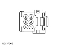 - Is the resistance greater than 10,000 ohms?
| Yes
INSTALL a new start/stop switch. REFER to
Start/Stop Switch
.
No
REPAIR the circuit.
|
|
I3 CHECK THE MODE INDICATOR CIRCUIT FOR A SHORT TO VOLTAGE
|
|
| Yes
REPAIR the circuit.
No
GO to
I4
.
|
|
I4 CHECK THE MODE INDICATOR CIRCUIT FOR AN OPEN
|
|
- Ignition OFF.
- Disconnect:
C2280B .
- Measure the
resistance
between:
| Positive Lead
| Negative Lead
| | Pin
| Circuit
| Pin
| Circuit
| | C2280B-42
| CPK36 (VT/BN)
| C2195-2
| CPK36 (VT/BN)
|
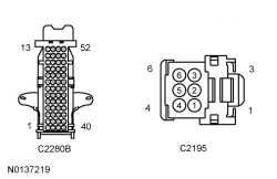 - Is the resistance less than 3 ohms?
| Yes
INSTALL a new start/stop switch. REFER to
Start/Stop Switch
.
No
REPAIR the circuit.
|
|
I5 CHECK START/STOP SWITCH INDICATOR
|
|
- Ignition OFF.
- Disconnect:
C2280B .
- Connect a
fused jumper wire
between:
| Lead 1
| Lead 2
| | Pin
| Circuit
| Pin
| Circuit
| | C2280B-42
| CPK36 (VT/BN)
| —
| Battery positive post
|
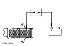 - Does the start/stop switch mode indicator illuminate?
| Yes
REMOVE the fused jumper wire. GO to
I6
.
No
INSTALL a new start/stop switch. REFER to
Start/Stop Switch
.
|
|
I6 CHECK FOR CORRECT BCM OPERATION
|
|
- Disconnect and inspect all
connectors.
- Repair:
- corrosion (install new connector or terminals - clean module pins)
- damaged or bent pins - install new terminals/pins
- pushed-out pins - install new pins as necessary
- Reconnect the
connectors and all previously disconnected exterior system connectors. Make sure they seat and latch correctly.
- Operate the system and determine if the concern is still present.
- Is the concern still present?
| Yes
CHECK
for any applicable TSBs. If a TSB exists for this concern, DISCONTINUE this test and FOLLOW TSB instructions. If no TSBs address this concern, INSTALL a new
. REFER to
Section 419-10
.
No
The system is operating correctly at this time. The concern may have been caused by module connections. ADDRESS the root cause of any connector or pin issues.
|
Pinpoint Test J: B108A:01 or B1142:29
Diagnostic Overview
Diagnostics in this manual assume a certain skill level and knowledge of Ford-specific diagnostic practices. Refer to Diagnostic Methods in
Section 100-00
for information about these practices.
Refer to Wiring Diagrams Cell
13
, Power Distribution/BCM for schematic and connector information.
Normal Operation and Fault Conditions
On vehicles equipped with a conventional ignition switch, fused battery voltage is sent to the ignition switch from
fuse 26 (5A). This voltage is then sent to the
along 1 of 3 circuits, depending on ignition switch position.
On vehicles equipped with a start/stop switch, fused battery voltage is sent to one set of contacts in the start/stop switch from
fuse 26 (5A). When the switch is pressed, this voltage is sent to the
, the
module and the PCM. The other set of contacts in the start/stop switch connects the
to ground. When the switch is pressed, the
detects this ground signal and takes appropriate action, based on other inputs.
DTC Fault Trigger Conditions
| DTC
| Description
| Fault Trigger Conditions
|
|---|
| Start Button: General Electrical Failure
| This DTC sets if the
does not receive any ignition signal during a
self-test or normal operation.
|
| Ignition Status 1: Signal Invalid
| This DTC sets when the
does not receive a valid ignition signal during a
self-test.
|
Possible Sources
- Fuse
- Wiring, terminals or connectors
- Start/stop switch
Visual Inspection and Diagnostic Pre-checks
- Make sure
fuse 26 (5A) is OK.
PINPOINT TEST J: B108A:01 OR B1142:29
| Test Step
| Result / Action to Take
|
|---|
|
J1 IDENTIFY THE IGNITION SYSTEM
|
|
- Verify that the vehicle is equipped with a start/stop switch.
- Is the vehicle equipped with a start/stop switch?
| Yes
GO to
J6
.
No
GO to
J2
.
|
|
J2 CHECK THE IGNITION SWITCH STATE (IGN_SW_STATE) PID
|
|
- Ignition ON.
- Enter the following diagnostic mode on the scan tool: DataLogger —
.
- Monitor the IGN_SW_STATE PID while turning the ignition switch through all 4 positions (OFF, ACC, RUN and START).
- Does the PID match each ignition switch position?
| Yes
GO to
J13
.
No
GO to
J3
.
|
|
J3 CHECK THE ACC CIRCUIT FOR AN OPEN OR SHORT TO VOLTAGE
|
|
- Ignition In ACC.
- Monitor the IGN_SW_STATE PID with the ignition switch in the ACC position.
- Does the PID display "Acc"?
| Yes
GO to
J4
.
No
If the PID displays "Off" or "Unknown", REPAIR circuit CDC33 (VT) for an open.
If the PID displays "Run" or "Start", REPAIR circuit CDC34 (WH/OG) (RUN) or CDC35 (BU/WH) (START) for a short to voltage.
|
|
J4 CHECK THE RUN CIRCUIT FOR AN OPEN OR SHORT TO VOLTAGE
|
|
- Ignition ON.
- Monitor the IGN_SW_STATE PID with the ignition switch in the RUN position.
- Does the PID display "Run"?
| Yes
GO to
J5
.
No
If the PID displays "Off" or "Unknown", REPAIR circuit CDC34 (WH/OG) for an open.
If the PID displays "Acc" or "Start", REPAIR circuit CDC33 (VT) (ACC) or CDC35 (BU/WH) (START) for a short to voltage.
|
|
J5 CHECK THE START CIRCUIT FOR AN OPEN OR SHORT TO VOLTAGE
|
|
- Monitor the IGN_SW_STATE PID with the ignition switch in the START position.
- Does the PID display "Start"?
| Yes
GO to
J13
.
No
If the PID displays "Off" or "Unknown", REPAIR circuit CDC35 (BU/WH) for an open.
If the PID displays "Acc" or "Run", REPAIR circuit CDC33 (VT) (ACC) or CDC34 (WH/OG) (RUN) for a short to voltage.
|
|
J6 CHECK FOR RFA MODULE DTC
|
|
- Enter the following diagnostic mode on the scan tool: Self Test —
module .
- Record all
module DTCs.
- Is DTC B108A:12 present?
| Yes
GO to Pinpoint Test K
.
No
GO to
J7
.
|
|
J7 CHECK THE START/STOP SWITCH
|
|
| Yes
GO to
J8
.
No
INSTALL a new start/stop switch. REFER to
Start/Stop Switch
.
|
|
J8 CHECK FOR VOLTAGE TO THE START/STOP SWITCH
|
|
- Measure the
voltage
between:
| Positive Lead
| Negative Lead
| | Pin
| Circuit
| Pin
| Circuit
| | C2195-4
| SBP26 (YE/RD)
| —
| Ground
|
 - Is the voltage greater than 11 volts?
| Yes
GO to
J9
.
No
VERIFY
fuse 26 (5A) is OK. If OK, REPAIR the circuit. If not OK, REFER to the Wiring Diagrams manual to identify the possible cause of the circuit short.
|
|
J9 CHECK THE START/STOP SWITCH VOLTAGE INPUT CIRCUIT FOR AN OPEN
|
|
- Disconnect:
C2280B .
- Measure the
resistance
between:
| Positive Lead
| Negative Lead
| | Pin
| Circuit
| Pin
| Circuit
| | C2280B-41
| CDC35 (BU/WH)
| C2195-1
| CDC35 (BU/WH)
|
 - Is the resistance less than 3 ohms?
| Yes
GO to
J10
.
No
REPAIR the circuit.
|
|
J10 CHECK THE BCM START/STOP SWITCH GROUND INPUT CIRCUIT FOR AN OPEN
|
|
- Measure the
resistance
between:
| Positive Lead
| Negative Lead
| | Pin
| Circuit
| Pin
| Circuit
| | C2280B-44
| CPK35 (YE)
| C2195-6
| CPK35 (YE)
|
 - Is the resistance less than 3 ohms?
| Yes
GO to
J11
.
No
REPAIR the circuit.
|
|
J11 CHECK THE BCM START/STOP SWITCH GROUND INPUT CIRCUIT FOR A SHORT TO GROUND
|
|
- Measure the
resistance
between:
| Positive Lead
| Negative Lead
| | Pin
| Circuit
| Pin
| Circuit
| | C2195-6
| CPK35 (YE)
| —
| Ground
|
 - Is the resistance to ground greater than 10,000 ohms?
| Yes
GO to
J12
.
No
REPAIR the circuit.
|
|
J12 CHECK THE START/STOP SWITCH GROUND CIRCUIT FOR AN OPEN
|
|
- Measure the
resistance
between:
| Positive Lead
| Negative Lead
| | Pin
| Circuit
| Pin
| Circuit
| | C2195-3
| GD375 (BK/BU)
| —
| Ground
|
 - Is the resistance less than 3 ohms?
| Yes
GO to
J13
.
No
REPAIR the circuit.
|
|
J13 CHECK FOR CORRECT BCM OPERATION
|
|
- Disconnect and inspect all
connectors.
- Repair:
- corrosion (install new connector or terminals - clean module pins)
- damaged or bent pins - install new terminals/pins
- pushed-out pins - install new pins as necessary
- Reconnect the
connectors and all previously disconnected exterior system connectors. Make sure they seat and latch correctly.
- Operate the system and determine if the concern is still present.
- Is the concern still present?
| Yes
CHECK
for any applicable TSBs. If a TSB exists for this concern, DISCONTINUE this test and FOLLOW TSB instructions. If no TSBs address this concern, INSTALL a new
. REFER to
Section 419-10
.
No
The system is operating correctly at this time. The concern may have been caused by module connections. ADDRESS the root cause of any connector or pin issues.
|
Pinpoint Test K: B108A:12
Diagnostic Overview
Diagnostics in this manual assume a certain skill level and knowledge of Ford-specific diagnostic practices. Refer to Diagnostic Methods in
Section 100-00
for information about these practices.
Refer to Wiring Diagrams Cell
13
, Power Distribution/BCM for schematic and connector information.
NOTE:
The
module is only capable of setting DTC B108A:12 as a continuous memory DTC. It is possible for this DTC to be cleared and not return, even if the condition that caused it is still present. If DTC B108A:12 is retrieved, carry out this pinpoint test even if the DTC does not return.
Normal Operation and Fault Conditions
Fused battery voltage is sent to one set of contacts in the start/stop switch from
fuse 26 (5A). When the switch is pressed, this voltage is sent to the
, the
module and the PCM. The other set of contacts in the start/stop switch connects the
to ground. When the switch is pressed, the
detects this ground signal and takes appropriate action, based on other inputs.
DTC Fault Trigger Conditions
| DTC
| Description
| Fault Trigger Conditions
|
|---|
| Start Button: Circuit Short to Battery
| This DTC sets if the
module detects a short to voltage on the start/stop switch input circuit, or if start/stop switch is stuck in the closed position.
|
Possible Sources
- Wiring, terminals or connectors
- Start/stop switch
- PCM
- module
PINPOINT TEST K: B108A:12
| Test Step
| Result / Action to Take
|
|---|
|
K1 CHECK THE START/STOP SWITCH 1 (CRK_FACT_B1) PID
|
|
- Enter the following diagnostic mode on the scan tool: DataLogger —
module .
- Monitor the
module PID Crk_Fact_B1 while pressing and releasing the start/stop switch.
- Does the PID display YES when the start/stop switch is pressed and NO when the start/stop switch is released?
| Yes
GO to
K5
.
No
If the Crk_Fact_B1 PID displays YES at all times, GO to
K2
.
|
|
K2 ISOLATE THE PCM
|
|
- Disconnect: PCM C175B (3.5L
) .
- Disconnect: PCM C1381B (3.5L
) .
- Monitor the
module PID Crk_Fact_B1.
- Does the PID change from YES to NO when the PCM is disconnected?
| Yes
INSTALL a new PCM. REFER to
Section 303-14
.
No
GO to
K3
.
|
|
K3 ISOLATE THE BCM
|
|
- Disconnect:
C2280B .
- Monitor the
module PID Crk_Fact_B1.
- Does the PID change from YES to NO when the
is disconnected?
| Yes
INSTALL a new
. REFER to
Section 419-10
.
No
GO to
K4
.
|
|
K4 ISOLATE THE START/STOP SWITCH
|
|
- Disconnect: Start/Stop Switch C2195 .
- Monitor the
module PID Crk_Fact_B1.
- Does the PID change from YES to NO when the start/stop switch is disconnected?
| Yes
INSTALL a new start/stop switch. REFER to
Start/Stop Switch
.
No
REPAIR circuit CDC35 (BU/WH).
|
|
K5 CHECK FOR CORRECT RFA MODULE OPERATION
|
|
- Disconnect and inspect all
module connectors.
- Repair:
- corrosion (install new connector or terminals - clean module pins)
- damaged or bent pins - install new terminals/pins
- pushed-out pins - install new pins as necessary
- Reconnect the
module connectors and all previously disconnected exterior system connectors. Make sure they seat and latch correctly.
- Operate the system and determine if the concern is still present.
- Is the concern still present?
| Yes
CHECK
for any applicable TSBs. If a TSB exists for this concern, DISCONTINUE this test and FOLLOW TSB instructions. If no TSBs address this concern, INSTALL a new
module. REFER to
Section 419-10
.
No
The system is operating correctly at this time. The concern may have been caused by module connections. ADDRESS the root cause of any connector or pin issues.
|
Pinpoint Test L: C0051:16 or C0051:17
Diagnostic Overview
Diagnostics in this manual assume a certain skill level and knowledge of Ford-specific diagnostic practices. Refer to Diagnostic Methods in
Section 100-00
for information about these practices.
Normal Operation and Fault Conditions
The steering wheel position sensor (also known as the steering wheel rotation sensor) uses 2 optical sensors to monitor the steering wheel position relative to the center position when the ignition is in RUN. The steering wheel position sensor transmits this data to the
which processes the data and transmits it on the
. When either DTC C0051:16 or C0051:17 is set, the
ignores the input from the steering wheel position sensor and transmits a fault message on the
.
DTC Fault Trigger Conditions
| DTC
| Description
| Fault Trigger Conditions
|
|---|
| Steering Wheel Position Sensor: Circuit Voltage Below Threshold
| This DTC sets if the data received by the
from either of the 2 optical sensors is below a predetermined threshold.
|
| Steering Wheel Position Sensor: Circuit Voltage Above Threshold
| If the data received by the
from either of the 2 optical sensors is above a predetermined threshold
|
Possible Sources
- Wiring, terminals or connectors
- Steering wheel rotation sensor
PINPOINT TEST L: C0051:16 OR C0051:17
| Test Step
| Result / Action to Take
|
|---|
|
L1 CHECK FOR SCCM DTC
|
|
- Enter the following diagnostic mode on the scan tool: Self Test —
.
- Record all
DTCs.
- Is DTC B11D9:16 and/or B11D9:17 present?
| Yes
DIAGNOSE DTCs B11D9:16 and 17 before diagnosing DTCs C0051:16 or C0051:17.
For DTC B11D9:16,
GO to Pinpoint Test M
.
For DTC B11D9:17,
GO to Pinpoint Test N
.
No
GO to
L2
.
|
|
L2 CHECK THE STEERING WHEEL ANGLE SENSOR STATUS (SW_ANG_SENS) PID
|
|
- Enter the following diagnostic mode on the scan tool: DataLogger —
.
- Monitor the
PID SW_ANG_SENS.
- Does the PID display CORRECT?
| Yes
The condition that caused the DTC to set is not present at this time. CLEAR the DTCs. DRIVE the vehicle for more than 1 minute at a speed greater than 32 km/h (19.9 mph) and make at least 1 left turn and 1 right turn. If the DTCs do not return, RETURN the vehicle to the customer. If the DTCs return, GO to
L3
No
If the PID displays FAULT, INSTALL a new steering wheel rotation sensor. REFER to
Section 206-09
.
If the PID displays PSCM NOT INITIALIZED, GO to
L3
.
|
|
L3 CHECK FOR CORRECT SCCM OPERATION
|
|
- Disconnect and inspect all
connectors.
- Repair:
- corrosion (install new connector or terminals - clean module pins)
- damaged or bent pins - install new terminals/pins
- pushed-out pins - install new pins as necessary
- Reconnect the
connectors and all previously disconnected exterior system connectors. Make sure they seat and latch correctly.
- Operate the system and determine if the concern is still present.
- Is the concern still present?
| Yes
CHECK
for any applicable TSBs. If a TSB exists for this concern, DISCONTINUE this test and FOLLOW TSB instructions. If no TSBs address this concern, INSTALL a new
. REFER to
Steering Column Control Module (SCCM)
.
No
The system is operating correctly at this time. The concern may have been caused by module connections. ADDRESS the root cause of any connector or pin issues.
|
Pinpoint Test M: B11D9:16
Diagnostic Overview
Diagnostics in this manual assume a certain skill level and knowledge of Ford-specific diagnostic practices. Refer to Diagnostic Methods in
Section 100-00
for information about these practices.
Refer to Wiring Diagrams Cell
42
, Vehicle Dynamic Systems for schematic and connector information.
Normal Operation and Fault Conditions
The
continuously monitors input voltage for correct operation. If voltage outside of defined limits is detected by the
, the applicable DTC sets. DTC B11D9:16 can set if the vehicle battery has been discharged. The vehicle battery may become discharged due to excessive load(s) on the charging system from aftermarket accessories or if the vehicle has been left unattended with the accessories on.
DTC Fault Trigger Conditions
| DTC
| Description
| Fault Trigger Conditions
|
|---|
| Vehicle Battery: Circuit Below Threshold
| This DTC sets in continuous memory if the
detects battery voltage below 8 volts on the battery voltage supply circuit.
|
Possible Sources
- Battery
- Fuse(s)
- Wiring, terminals or connectors
- Charging system
Visual Inspection and Diagnostic Pre-checks
- Make sure the vehicle battery terminals and cables are free of any corrosion and other contaminates.
- Make sure the vehicle battery terminals are tightened to their correct torque specifications.
PINPOINT TEST M: B11D9:16
| Test Step
| Result / Action to Take
|
|---|
|
M1 CHECK FOR SCCM DTC
|
|
- Ignition ON.
- Enter the following diagnostic mode on the scan tool: Self Test —
.
- Enter the following diagnostic mode on the scan tool: Clear DTCs —
.
- Enter the following diagnostic mode on the scan tool: Self Test —
.
- Is DTC B119D:16 still present?
| Yes
GO to
M2
.
No
The system is operating normally at this time. The DTC may have been set previously during battery charging or while jump starting the vehicle.
|
|
M2 CHECK FOR CHARGING SYSTEM DTC IN THE PCM
|
|
- Enter the following diagnostic mode on the scan tool: Self Test — PCM .
- Record all
from the PCM.
- Are any charging system DTCs present in the PCM?
| Yes
REFER to
Section 303-14
to diagnose the charging system DTCs.
No
GO to
M3
.
|
|
M3 CHECK THE BATTERY CONDITION AND STATE OF CHARGE
|
|
- Ignition OFF.
- Carry out the Battery Condition Test. REFER to
Section 414-01
.
- Is the battery OK?
| Yes
GO to
M4
.
No
CORRECT the battery condition.
|
|
M4 CHECK THE SCCM VOLTAGE SUPPLY
|
|
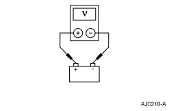
- Measure and record battery voltage.
 - Select PARK.
- Disconnect:
C2414A .
- Disconnect:
C2414B .
- Measure the
voltage
between:
| Positive Lead
| Negative Lead
| | Pin
| Circuit
| Pin
| Circuit
| | C2414A-5
| SBP23 (WH/RD)
| —
| Ground
|
 - Measure the
voltage
between:
| Positive Lead
| Negative Lead
| | Pin
| Circuit
| Pin
| Circuit
| | C2414B-8
| SBP24 (VT/RD)
| —
| Ground
|
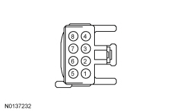 - Are the voltages within 0.2 volt of the recorded battery voltage?
| Yes
GO to
M5
.
No
VERIFY
fuses 23 (15A) and 24 (15A) are OK. If OK, REPAIR the affected circuit(s). If not OK, REFER to the Wiring Diagrams manual to identify the possible causes of the circuit short.
|
|
M5 CHECK THE SCCM GROUND CIRCUIT
|
|
- Disconnect the battery negative cable. REFER to
Section 414-01
.
- Measure the
resistance
between:
| Positive Lead
| Negative Lead
| | Pin
| Circuit
| Pin
| Circuit
| | C2414A-2
| GD375 (BK/BU)
| —
| Ground
|
 - Measure the
resistance
between:
| Positive Lead
| Negative Lead
| | Pin
| Circuit
| Pin
| Circuit
| | C2414B-5
| GD375 (BK/BU)
| —
| Ground
|
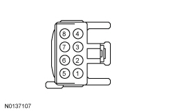 - Are the resistances less than 3 ohms?
| Yes
CONNECT the battery negative cable. GO to
M6
.
No
REPAIR the circuit(s). CONNECT the battery negative cable.
|
|
M6 CHECK FOR CORRECT SCCM OPERATION
|
|
- Disconnect and inspect all
connectors.
- Repair:
- corrosion (install new connector or terminals - clean module pins)
- damaged or bent pins - install new terminals/pins
- pushed-out pins - install new pins as necessary
- Reconnect the
connectors and all previously disconnected exterior system connectors. Make sure they seat and latch correctly.
- Operate the system and determine if the concern is still present.
- Is the concern still present?
| Yes
CHECK
for any applicable TSBs. If a TSB exists for this concern, DISCONTINUE this test and FOLLOW TSB instructions. If no TSBs address this concern, INSTALL a new
. REFER to
Steering Column Control Module (SCCM)
.
No
The system is operating correctly at this time. The concern may have been caused by module connections. ADDRESS the root cause of any connector or pin issues.
|
Pinpoint Test N: B11D9:17
Diagnostic Overview
Diagnostics in this manual assume a certain skill level and knowledge of Ford-specific diagnostic practices. Refer to Diagnostic Methods in
Section 100-00
for information about these practices.
Refer to Wiring Diagrams Cell
13
, Power Distribution/BCM for schematic and connector information.
Normal Operation and Fault Conditions
The
continuously monitors input voltage for correct operation. If voltage outside of defined limits is detected by the
, the applicable DTC sets. DTC B11D9:17 can set if the vehicle has been recently jump started or the vehicle battery has been recently charged.
DTC Fault Trigger Conditions
| DTC
| Description
| Fault Trigger Conditions
|
|---|
| Vehicle Battery: Circuit Above Threshold
| This DTC is set in continuous memory if the
detects battery voltage above 19 volts on the battery voltage supply circuit.
|
Possible Sources
- Wiring, terminals or connectors
- Charging system
PINPOINT TEST N: B11D9:17
| Test Step
| Result / Action to Take
|
|---|
|
N1 CHECK FOR HIGH BATTERY VOLTAGE AND/OR CHARGING SYSTEM DTC IN THE PCM
|
|
- Ignition ON.
- Enter the following diagnostic mode on the scan tool: Self Test — PCM .
- Record all PCM
.
- Are any high battery voltage and/or charging system DTCs present in the PCM?
| Yes
REFER to
Section 303-14
to diagnose an overcharging condition.
No
GO to
N2
.
|
|
N2 CHECK THE BATTERY VOLTAGE
|
|
- Turn off all interior/exterior lights and accessories.
- Start and run the engine at approximately 2,000 rpm for 3 minutes while monitoring the battery voltage.
- Does the battery voltage rise to 16.5 volts or higher?
| Yes
REFER to
Section 414-00
to diagnose an overcharging condition.
No
GO to
N3
.
|
|
N3 RECHECK FOR SCCM DTC B119D:17
|
|
- Using a scan tool, perform
self-test.
- Clear the
DTCs and repeat the self-test.
- Is DTC B11D9:17 present in the
?
| Yes
GO to
N4
.
No
The system is operating normally at this time. The DTC may have been set previously during battery charging or while jump starting the vehicle.
|
|
N4 CHECK FOR CORRECT SCCM OPERATION
|
|
- Disconnect and inspect all
connectors.
- Repair:
- corrosion (install new connector or terminals - clean module pins)
- damaged or bent pins - install new terminals/pins
- pushed-out pins - install new pins as necessary
- Reconnect the
connectors and all previously disconnected exterior system connectors. Make sure they seat and latch correctly.
- Operate the system and determine if the concern is still present.
- Is the concern still present?
| Yes
CHECK
for any applicable TSBs. If a TSB exists for this concern, DISCONTINUE this test and FOLLOW TSB instructions. If no TSBs address this concern, INSTALL a new
. REFER to
Steering Column Control Module (SCCM)
.
No
The system is operating correctly at this time. The concern may have been caused by module connections. ADDRESS the root cause of any connector or pin issues.
|
Pinpoint Test O: B1310:12
Diagnostic Overview
Diagnostics in this manual assume a certain skill level and knowledge of Ford-specific diagnostic practices. Refer to Diagnostic Methods in
Section 100-00
for information about these practices.
Refer to Wiring Diagrams Cell
13
, Power Distribution/BCM for schematic and connector information.
Normal Operation and Fault Conditions
When the ignition is placed in RUN mode, the
provides a ground for the coil (control) side of the RUN/START relay located in the
. The
monitors the RUN/START relay control circuit and sets a DTC if the circuit is shorted to voltage.
DTC Fault Trigger Conditions
| DTC
| Description
| Fault Trigger Conditions
|
|---|
| Run/Start Control: Circuit Short to Battery
| This DTC is set if the
detects a short to battery in the RUN/START relay control circuit during a
self-test or during normal operation.
|
Possible Sources
- Wiring, terminals or connectors
- RUN/START relay
PINPOINT TEST O: B1310:12
| Test Step
| Result / Action to Take
|
|---|
|
O1 CHECK THE RUN/START RELAY
|
|
| Yes
GO to
O2
.
No
INSTALL a new RUN/START relay.
|
|
O2 CHECK THE RUN/START RELAY CONTROL CIRCUIT FOR A SHORT TO VOLTAGE
|
|
- Disconnect:
C2280F .
- Measure the
voltage
between:
| Positive Lead
| Negative Lead
| | Pin
| Circuit
| Pin
| Circuit
| | RUN/START relay-1
| CDC55 (BN/VT)
| —
| Ground
|
 - Is any voltage present?
| Yes
REPAIR the circuit.
No
GO to
O3
.
|
|
O3 CHECK FOR CORRECT BCM OPERATION
|
|
- Disconnect and inspect all
connectors.
- Repair:
- corrosion (install new connector or terminals - clean module pins)
- damaged or bent pins - install new terminals/pins
- pushed-out pins - install new pins as necessary
- Reconnect the
connectors and all previously disconnected exterior system connectors. Make sure they seat and latch correctly.
- Operate the system and determine if the concern is still present.
- Is the concern still present?
| Yes
CHECK
for any applicable TSBs. If a TSB exists for this concern, DISCONTINUE this test and FOLLOW TSB instructions. If no TSBs address this concern, INSTALL a new
. REFER to
Section 419-10
.
No
The system is operating correctly at this time. The concern may have been caused by module connections. ADDRESS the root cause of any connector or pin issues.
|
Component Tests
Ignition Switch — Mechanical
The following conditions can cause difficulty in operating the ignition switch and lock cylinder:
- Burrs on the lock cylinder key
- Insufficient lube on the lock cylinder
- Binding lock cylinder
- Burrs or foreign material around the rack-and-pinion actuator in the lock cylinder housing
- Insufficient lube on the actuator (Do not apply lubricant to the inside of the ignition switch.)
- Binding ignition switch
Carry out the following test to determine if the ignition switch and lock cylinder are operating correctly.
- Inspect the ignition key for any burrs, damage or incorrect cut. Have a new ignition key made as necessary.
- Turn the key to the ACC position and then the RUN position.
- If the ignition key turns to the ACC and RUN position, continue with Step 3.
- If the ignition key will not turn to the ACC and RUN position, continue with Step 4.
NOTE:
The ignition switch and lock cylinder should return from the START position back to the RUN position without assistance.
Turn the ignition key to the START position and release the key.
- If the ignition switch and lock cylinder return from the START position back to the RUN position without assistance, the ignition switch is operating correctly at this time.
- If the ignition switch and lock cylinder do not return from the START position back to the RUN position without assistance, continue with Step 4.
- Remove the ignition lock cylinder. Refer to
Section 501-14A
.
- Rotate the ignition lock cylinder through all of the switch positions.
- If the lock cylinder operates correctly, install a new ignition switch. Refer to
Ignition Switch
.
- If the lock cylinder does not operate correctly, install a new ignition lock cylinder. Refer to
Section 501-14A
.
Ignition Switch — Electrical
Refer to Wiring Diagrams Cell
149
for component testing.
Start/Stop Switch — Electrical
Refer to Wiring Diagrams Cell
149
for component testing.


