SECTION 413-00: Instrument Cluster and Panel Illumination
| 2014 Flex Workshop Manual
|
DIAGNOSIS AND TESTING
| Procedure revision date: 05/02/2013
|
Instrument Cluster and Panel Illumination
Charts
Diagnostics in this manual assume a certain skill level and knowledge of Ford-specific diagnostic practices. Refer to
Section 100-00
for information about these diagnostic practices.
Related Module DTC Chart —
| DTC
| Description
| Action
|
|---|
| B1315:11
| Backlighting (Non Reflective Controls) Illumination Output: Circuit Short to Ground
| GO to Pinpoint Test B
.
|
| B1315:15
| Backlighting (Non Reflective Controls) Illumination Output: Circuit Short To Battery or Open
| GO to Pinpoint Test C
.
|
| All Other DTCs
| —
| REFER to
Section 419-10
.
|
Related Module DTC Chart —
Symptom Chart
Diagnostics in this manual assume a certain skill level and knowledge of Ford-specific diagnostic practices. Refer to
Section 100-00
for information about these diagnostic practices.
Symptom Chart: Instrument Cluster and Panel Illumination
| Condition
| Possible Sources
| Action
|
|---|
- A module does not respond to the scan tool
| - Fuse
- Wiring, terminals or connectors
- Module
| |
- All dimmable illumination does not dim
| - Refer to the Diagnostic Routine
| |
- All dimmable non-networked illumination is inoperative
| - Refer to the Diagnostic Routine
| |
- All dimmable non-networked illumination is always on
| - Refer to the Diagnostic Routine
| |
- The steering wheel switch illumination is inoperative
| - Refer to the Diagnostic Routine
| |
- One or more switch or component illumination is inoperative
| - Refer to the Diagnostic Routine
| |
- The right front or either rear window control switch illumination is inoperative
| | - VERIFY the operation of the power windows.
- If the power windows operate correctly, INSTALL a new window control switch. REFER to
Section 501-11
.
- If the power windows do not operate correctly, REFER to
Section 501-11
.
|
- The left front window control switch illumination is inoperative
| - Wiring, terminals or connectors
- Window control switch
| - VERIFY the operation of the power mirrors.
- If the power mirrors operate correctly, INSTALL a new window control switch. REFER to
Section 501-11
.
|
- The
illumination is inoperative/does not dim
| | - CARRY OUT the network test.
- If the scan tool responds with no communication with the
, REFER to
Section 418-00
.
- If the scan tool communicates with the
, INSTALL a new
. REFER to
Section 413-01
.
|
- The
illumination is inoperative/does not dim
| | - CARRY OUT the network test.
- If the scan tool responds with no communication with the
, REFER to
Section 418-00
.
- If the scan tool communicates with the
, INSTALL a new
. Refer to the appropriate section in Group
415
for the procedure.
|
- The
illumination is inoperative/does not dim
| | - CHECK for normal operation of the audio system.
- If the audio system operates correctly, INSTALL a new
. REFER to
Section 415-00A
.
- If the audio system does not operate correctly, REFER to
Section 415-00A
to diagnose the audio system does not operate correctly from the
.
|
- The
illumination is inoperative/does not dim
| | - CHECK for normal operation of the audio system.
- If the audio system operates correctly, INSTALL a new
. REFER to
Section 415-00B
(8-Inch (203 mm) Touchscreen, 7 Speakers) or
Section 415-00C
(Sony® Sound 8-Inch (203 mm) Touchscreen, 12 Speakers).
- If the audio system does not operate correctly, REFER to
Section 415-00B
(8-Inch (203 mm) Touchscreen, 7 Speakers) or
Section 415-00C
(Sony® Sound 8-Inch (203 mm) Touchscreen, 12 Speakers) to diagnose the audio system does not operate correctly from the
.
|
Pinpoint Tests
Pinpoint Test A: All Dimmable Illumination Does Not Dim
Diagnostic Overview
Diagnostics in this manual assume a certain skill level and knowledge of Ford-specific diagnostic practices. Refer to Diagnostic Methods in
Section 100-00
for information about these practices.
Refer to Wiring Diagrams Cell
71
, Cluster and Panel Illumination for schematic and connector information.
Normal Operation and Fault Conditions
Refer to
Instrument Cluster and Panel Illumination
.
DTC Fault Trigger Conditions
| DTC
| Description
| Fault Trigger Conditions
|
|---|
| Lamp Fade Control: Component Failure
| Sets when the
detects a short to ground from the instrument panel dimmer switch up/down input or dome lamp request input circuits.
|
Possible Sources
- Wiring, terminals or connectors
- Instrument panel dimmer switch
PINPOINT TEST A: ALL DIMMABLE ILLUMINATION DOES NOT DIM
| Test Step
| Result / Action to Take
|
|---|
|
A1 CHECK THE RECORDED RESULTS FROM THE
ON-DEMAND SELF-TEST
|
|
- Ignition ON.
- Using a scan tool, perform the
self-test.
- Is DTC B1124:09 present?
| Yes
GO to
A2
.
No
GO to
A4
.
|
|
A2 CHECK THE INSTRUMENT PANEL DIMMER SWITCH
|
|
- Ignition OFF.
- Disconnect: Instrument Panel Dimmer Switch C2065.
- Ignition ON.
- Using a scan tool, clear the DTCs and perform the
self-test.
- Is DTC B1124:09 still present?
| Yes
GO to
A3
.
No
INSTALL a new instrument panel dimmer switch. REFER to
Instrument Panel Dimmer Switch
.
|
|
A3 CHECK THE INSTRUMENT PANEL DIMMER SWITCH INPUT CIRCUITS FOR A SHORT TO GROUND
|
|
- Ignition OFF.
- Disconnect:
C2414A.
- Measure the
resistance
between:
| Positive Lead
| Negative Lead
| | Pin
| Circuit
| Pin
| Circuit
| | C2065-2
| VLN36 (GY/OG)
| —
| Ground
| | C2065-3
| CLN56 (BN/VT)
| —
| Ground
| | C2065-7
| CLN55 (YE/VT)
| —
| Ground
|
 - Are the resistances greater than 10,000 ohms?
| Yes
GO to
A9
.
No
REPAIR the affected circuit.
|
|
A4 CHECK THE INSTRUMENT PANEL DIMMER SWITCH
|
|
| Yes
GO to
A5
.
No
INSTALL a new instrument panel dimmer switch. REFER to
Instrument Panel Dimmer Switch
.
|
|
A5 CHECK THE INSTRUMENT PANEL DIMMER SWITCH UP AND DOWN INPUT CIRCUITS FOR VOLTAGE
|
|
- Ignition ON.
- Measure the
voltage
between:
| Positive Lead
| Negative Lead
| | Pin
| Circuit
| Pin
| Circuit
| | C2065-3
| CLN56 (BN/VT)
| —
| Ground
| | C2065-7
| CLN55 (YE/VT)
| —
| Ground
|
 - Are the voltages greater than 5 volts?
| Yes
GO to
A7
.
No
GO to
A6
.
|
|
A6 CHECK THE INSTRUMENT PANEL DIMMER SWITCH UP AND DOWN INPUT CIRCUITS FOR AN OPEN
|
|
- Ignition OFF.
- Disconnect:
C2414A.
- Measure the
resistance
between:
| Positive Lead
| Negative Lead
| | Pin
| Circuit
| Pin
| Circuit
| | C2414A-17
| CLN56 (BN/VT)
| C2065-3
| CLN56 (BN/VT)
| | C2414A-18
| CLN55 (YE/VT)
| C2065-7
| CLN55 (YE/VT)
|
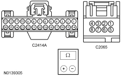 - Are the resistances less than 3 ohms?
| Yes
GO to
A9
.
No
REPAIR the affected circuit.
|
|
A7 CHECK THE INSTRUMENT PANEL DIMMER SWITCH INPUT AND RETURN CIRCUITS FOR A SHORT TO VOLTAGE
|
|
- Ignition OFF.
- Disconnect:
C2414A.
- Ignition ON.
- Measure the
voltage
between:
| Positive Lead
| Negative Lead
| | Pin
| Circuit
| Pin
| Circuit
| | C2065-2
| VLN36 (GY/OG)
| —
| Ground
| | C2065-3
| CLN56 (BN/VT)
| —
| Ground
| | C2065-4
| RLN29 (WH/OG)
| —
| Ground
| | C2065-7
| CLN55 (YE/VT)
| —
| Ground
|
 - Is any voltage present?
| Yes
REPAIR the affected circuit.
No
GO to
A8
.
|
|
A8 CHECK THE INSTRUMENT PANEL DIMMER SWITCH RETURN CIRCUIT FOR AN OPEN
|
|
- Ignition OFF.
- Measure the
resistance
between:
| Positive Lead
| Negative Lead
| | Pin
| Circuit
| Pin
| Circuit
| | C2414A-15
| RLN29 (WH/OG)
| C2065-4
| RLN29 (WH/OG)
|
 - Is the resistance less than 3 ohms?
| Yes
GO to
A9
.
No
REPAIR the circuit.
|
|
A9 CHECK THE INSTRUMENT PANEL DIMMER SWITCH INPUT AND RETURN CIRCUITS FOR A SHORT TOGETHER
|
|
- Measure the
resistance
between:
| Positive Lead
| Negative Lead
| | Pin
| Circuit
| Pin
| Circuit
| | C2065-2
| VLN36 (GY/OG)
| C2065-3
| CLN56 (BN/VT)
| | C2065-2
| VLN36 (GY/OG)
| C2065-4
| RLN29 (WH/OG)
| | C2065-2
| VLN36 (GY/OG)
| C2065-7
| CLN55 (YE/VT)
| | C2065-3
| CLN56 (BN/VT)
| C2065-4
| RLN29 (WH/OG)
| | C2065-3
| CLN56 (BN/VT)
| C2065-7
| CLN55 (YE/VT)
| | C2065-4
| RLN29 (WH/OG)
| C2065-7
| CLN55 (YE/VT)
|
 - Are the resistances greater than 10,000 ohms?
| Yes
GO to
A10
.
No
REPAIR the affected circuits.
|
|
A10 CHECK FOR CORRECT
OPERATION
|
|
- Disconnect and inspect all the
connectors.
- Repair:
- corrosion (install new connector or terminals – clean module pins)
- damaged or bent pins – install new terminals/pins
- pushed-out pins – install new pins as necessary
- Reconnect the
connectors. Make sure they seat and latch correctly.
- Operate the system and determine if the concern is still present.
- Is the concern still present?
| Yes
CHECK On-Line Automotive Service Information System (OASIS) for any applicable
. If a
exists for this concern, DISCONTINUE this test and FOLLOW
instructions. If no
address this concern, INSTALL a new
. REFER to
Section 211-05
.
No
The system is operating correctly at this time. The concern may have been caused by module connections. ADDRESS the root cause of any connector or pin issues.
|
Pinpoint Test B: All Dimmable Non-Networked Illumination Is Inoperative
Diagnostic Overview
Diagnostics in this manual assume a certain skill level and knowledge of Ford-specific diagnostic practices. Refer to Diagnostic Methods in
Section 100-00
for information about these practices.
Refer to Wiring Diagrams Cell
71
, Cluster and Panel Illumination for schematic and connector information.
Normal Operation and Fault Conditions
Refer to
Instrument Cluster and Panel Illumination
.
DTC Fault Trigger Conditions
| DTC
| Description
| Fault Trigger Conditions
|
|---|
| Backlighting (Non Reflective Controls) Illumination Output: Circuit Short To Ground
| Sets when the
detects a short to ground from the backlighting output circuit.
|
Possible Sources
- fuse 12 (15A)
- Wiring, terminals or connectors
PINPOINT TEST B: ALL DIMMABLE NON-NETWORKED ILLUMINATION IS INOPERATIVE
| Test Step
| Result / Action to Take
|
|---|
|
B1 BYPASS THE
|
|
- Ignition OFF.
- Disconnect:
C2280B.
- Connect a
fused jumper wire
between:
| Lead 1
| Lead 2
| | Pin
| Circuit
| Pin
| Circuit
| | C2280B-40
| VLN04 (VT/GY)
| —
| Battery positive
|
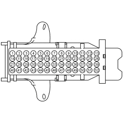 - Do the backlighting components illuminate?
| Yes
REMOVE the jumper wire. GO to
B2
.
No
VERIFY the
fuse 12 (15A) is OK. If OK, REMOVE the jumper wire. REPAIR the circuit. If not OK, REFER to the Wiring Diagrams manual to identify the possible causes of the circuit short.
|
|
B2 CHECK FOR CORRECT
OPERATION
|
|
- Disconnect and inspect all the
connectors.
- Repair:
- corrosion (install new connector or terminals – clean module pins)
- damaged or bent pins – install new terminals/pins
- pushed-out pins – install new pins as necessary
- Reconnect the
connectors. Make sure they seat and latch correctly.
- Operate the system and determine if the concern is still present.
- Is the concern still present?
| Yes
CHECK On-Line Automotive Service Information System (OASIS) for any applicable
. If a
exists for this concern, DISCONTINUE this test and FOLLOW
instructions. If no
address this concern, INSTALL a new
. REFER to
Section 419-10
.
No
The system is operating correctly at this time. The concern may have been caused by module connections. ADDRESS the root cause of any connector or pin issues.
|
Pinpoint Test C: All Dimmable Non-Networked Illumination Is Always On
Diagnostic Overview
Diagnostics in this manual assume a certain skill level and knowledge of Ford-specific diagnostic practices. Refer to Diagnostic Methods in
Section 100-00
for information about these practices.
Refer to Wiring Diagrams Cell
71
, Cluster and Panel Illumination for schematic and connector information.
Normal Operation and Fault Conditions
Refer to
Instrument Cluster and Panel Illumination
.
DTC Fault Trigger Conditions
| DTC
| Description
| Fault Trigger Conditions
|
|---|
| Backlighting (Non Reflective Controls) Illumination Output: Circuit Short To Battery or Open
| Sets when the
detects an open or a short to voltage from the backlighting output circuit.
|
Possible Sources
- Wiring, terminals or connectors
PINPOINT TEST C: ALL DIMMABLE NON-NETWORKED ILLUMINATION IS ALWAYS ON
| Test Step
| Result / Action to Take
|
|---|
|
C1 CHECK THE EXTERIOR LIGHTING
|
|
- Ignition OFF.
- Place the headlamp switch in the OFF position.
- Wait 1 minute and observe the parking lamps.
- Are the parking lights illuminated?
| Yes
REFER to
Section 417-01
.
No
GO to
C2
.
|
|
C2 CHECK THE
BACKLIGHTING OUTPUT CIRCUIT FOR A SHORT TO VOLTAGE
|
|
- Disconnect:
C2280B.
- Ignition ON.
- Do the dimmable backlighted components continue to illuminate?
| Yes
REPAIR circuit VLN04 (VT/GY).
No
GO to
C3
.
|
|
C3 CHECK FOR CORRECT
OPERATION
|
|
- Disconnect and inspect all the
connectors.
- Repair:
- corrosion (install new connector or terminals – clean module pins)
- damaged or bent pins – install new terminals/pins
- pushed-out pins – install new pins as necessary
- Reconnect the
connectors. Make sure they seat and latch correctly.
- Operate the system and determine if the concern is still present.
- Is the concern still present?
| Yes
CHECK On-Line Automotive Service Information System (OASIS) for any applicable
. If a
exists for this concern, DISCONTINUE this test and FOLLOW
instructions. If no
address this concern, INSTALL a new
. REFER to
Section 419-10
.
No
The system is operating correctly at this time. The concern may have been caused by module connections. ADDRESS the root cause of any connector or pin issues.
|
Pinpoint Test D: The Steering Wheel Switch Illumination Is Inoperative
Diagnostic Overview
Diagnostics in this manual assume a certain skill level and knowledge of Ford-specific diagnostic practices. Refer to Diagnostic Methods in
Section 100-00
for information about these practices.
Refer to Wiring Diagrams Cell
71
, Cluster and Panel Illumination for schematic and connector information.
Normal Operation and Fault Conditions
Refer to
Instrument Cluster and Panel Illumination
.
Possible Sources
- Wiring, terminals or connectors
- Steering wheel switch(es)
- Steering wheel harness
- Clockspring
PINPOINT TEST D: THE STEERING WHEEL SWITCH(ES) ILLUMINATION IS INOPERATIVE
| Test Step
| Result / Action to Take
|
|---|
|
D1 CHECK OTHER NON-NETWORK DIMMABLE LIGHTING SOURCES
|
|
- Ignition OFF.
- Place the headlamp switch in the parking lamps on position.
- Using the instrument panel dimmer switch, change the dimmable backlighting to its brightest setting.
- Are all non-networked dimmable backlighting sources inoperative?
| Yes
GO to Pinpoint Test A
.
No
If all steering wheel switches do not illuminate, GO to
D2
.
If an individual steering wheel switch does not illuminate, GO to
D5
.
|
|
D2 CHECK THE HORN OPERATION
|
|
- Push the driver air bag against the steering wheel to activate the horn.
- Does the horn sound?
| Yes
GO to
D3
.
No
REFER to
Section 413-06
.
|
|
D3 CHECK THE STEERING WHEEL BACKLIGHTING VOLTAGE SUPPLY CIRCUIT FOR AN OPEN
|
|
- Disconnect: Clockspring C218A.
- Ignition ON.
- Measure the
voltage
between:
| Positive Lead
| Negative Lead
| | Pin
| Circuit
| Pin
| Circuit
| | C218A-9
| VLN04 (VT/GY)
| —
| Ground
|
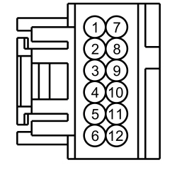 - Is the voltage greater than 11 volts?
| Yes
GO to
D4
.
No
REPAIR the circuit.
|
|
D4 CHECK THE STEERING WHEEL AND HARNESS
|
|
- Connect: Clockspring C218A.
- Remove the driver air bag module. Refer to
Section 501-20B
.
- Disconnect: Clockspring C218B.
- Connect: Battery Ground Cable.
- Place the headlamp switch in the parking lamps on position.
- Using the instrument panel dimmer switch, change the dimmable backlighting to its brightest setting.
- Measure the
component side voltage
between:
| Positive Lead
| Negative Lead
| | Pin
| Circuit
| Pin
| Circuit
| | C218B-9
| VLN04
| —
| Ground
|
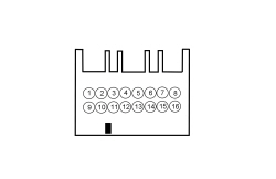 - Is the voltage greater than 11 volts?
| Yes
REPAIR the steering wheel harness for an open or INSTALL a new steering wheel. REFER to
Section 211-04
.
No
INSTALL a new clockspring. REFER to
Section 501-20B
.
|
|
D5 CHECK THE SUSPECT STEERING WHEEL SWITCH FOR VOLTAGE
|
|
- Remove the driver air bag module. Refer to
Section 501-20B
.
- Disconnect: Inoperative LH Steering Wheel Switch C2998 or RH Steering Wheel Switch C2999.
- Connect: Battery Ground Cable.
- Place the headlamp switch in the parking lamps on position.
- Using the instrument panel dimmer switch, change the dimmable backlighting to its brightest setting.
- Measure the
voltage
between:
| Positive Lead
| Negative Lead
| | Pin
| Circuit
| Pin
| Circuit
| | LH Steering Wheel Switch
| | C2998-10
| VLN04
| C2998-5
| RRH02
| | RH Steering Wheel Switch
| | C2999-6
| VLN04
| C2999-1
| RRH02
|
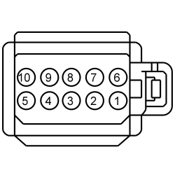 - Is the voltage greater than 11 volts?
| Yes
INSTALL a new LH or RH steering wheel switch. REFER to
Section 211-05
.
No
REPAIR the steering wheel harness for an open or INSTALL a new steering wheel. REFER to
Section 211-04
.
|
Pinpoint Test E: One Or More Switch Or Component Illumination Is Inoperative
Diagnostic Overview
Diagnostics in this manual assume a certain skill level and knowledge of Ford-specific diagnostic practices. Refer to Diagnostic Methods in
Section 100-00
for information about these practices.
Refer to Wiring Diagrams Cell
71
, Cluster and Panel Illumination for schematic and connector information.
Normal Operation and Fault Conditions
Refer to
Instrument Cluster and Panel Illumination
.
Possible Sources
- Wiring, terminals or connectors
- Illuminated switch
- Illuminated component
PINPOINT TEST E: ONE OR MORE ILLUMINATION SOURCE IS INOPERATIVE
| Test Step
| Result / Action to Take
|
|---|
|
E1 CHECK THE VOLTAGE TO THE SINGLE ILLUMINATION
|
|
NOTE:
If the instrument panel dimmer switch illumination is the inoperative source, increase the backlighting brightness to the highest setting before unplugging the instrument panel dimmer switch connector.
- Ignition OFF.
- Disconnect: Inoperative Illumination Source.
- Ignition ON.
- Place the headlamp switch in the parking lamps on position.
- Using the instrument panel dimmer switch, change the dimmable backlighting to its brightest setting.
- Measure the
voltage
between:
| Positive Lead
| Negative Lead
| | Pin
| Circuit
| Pin
| Circuit
| | Active Park Assist Switch
| | C3360-3
| VLN04 (VT/GY)
| —
| Ground
| | Headlamp Switch
| | C205-1
| VLN04 (VT/GY)
| —
| Ground
| | Start/Stop Switch
| | C2195-5
| VLN04 (VT/GY)
| —
| Ground
| | Power Liftgate Switch
| | C2269-3
| VLN04 (VT/GY)
| —
| Ground
| | Instrument Panel Dimmer Switch
| | C2065-1
| VLN04 (VT/GY)
| —
| Ground
| | Floor Shifter Inline
| | C3376F-6
| VLN04 (VT/GY)
| —
| Ground
| | Auxiliary Climate Control Assembly
| | C3198-18
| VLN04 (VT/GY)
| —
| Ground
| | Roof Opening Panel Switch
| | C912-2
| CBP32 (GN/VT)
| —
| Ground
| | LH Door Lock Switch
| | C505-3
| CBP32 (GN/VT)
| —
| Ground
| | RH Door Lock Switch
| | C605-3
| CBP32 (GN/VT)
| —
| Ground
|
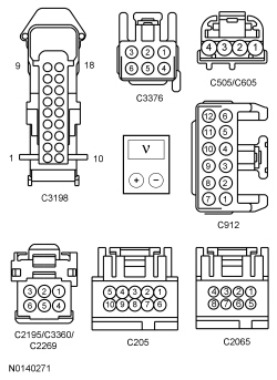 - Is the voltage greater than 11 volts?
| Yes
For start/stop switch, INSTALL a new start/stop switch. REFER to
Section 211-05
.
For instrument panel dimmer switch, INSTALL a new instrument panel dimmer switch. REFER to
Instrument Panel Dimmer Switch
.
For auxiliary climate control assembly, INSTALL a new auxiliary climate control assembly. REFER to
Section 412-01
.
For power liftgate switch, INSTALL a new power liftgate switch.
For roof opening panel switch, INSTALL a new roof opening panel switch.
For LH and RH door lock switches, INSTALL a new door lock switch. REFER to
Section 501-14A
.
For all other components, GO to
E2
.
No
REPAIR the circuit.
|
|
E2 CHECK THE GROUND CIRCUIT TO THE ILLUMINATION SOURCE FOR CONTINUITY
|
|
- Measure the
voltage
between:
| Positive Lead
| Negative Lead
| | Pin
| Circuit
| Pin
| Circuit
| | Active Park Assist Switch
| | C3360-3
| VLN04 (VT/GY)
| C3360-2
| GD375 (BK/BU)
| | Headlamp Switch
| | C205-1
| VLN04 (VT/GY)
| C205-8
| GD375 (BK/BU)
| | Floor Shifter Inline
| | C3376F-6
| VLN04 (VT/GY)
| C3376F-5
| GD375 (BK/BU)
|
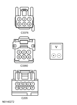 - Is the voltage greater than 11 volts?
| Yes
For active park assist switch, INSTALL a new active park assist switch. REFER to
Section 413-13B
.
For headlamp switch, INSTALL a new headlamp switch. REFER to
Section 417-01
.
For floor shifter, INSTALL a new selector lever bezel. REFER to
Section 307-05
.
No
REPAIR the circuit.
|


