SECTION 413-13A: Parking Aid — Audible
| 2014 Flex Workshop Manual
|
DIAGNOSIS AND TESTING
| Procedure revision date: 05/02/2013
|
Parking Aid
DTC Charts
Diagnostics in this manual assume a certain skill level and knowledge of Ford-specific diagnostic practices. Refer to Diagnostic Methods in
Section 100-00
for information about these practices.
Parking Aid Module (PAM) DTC Chart
| DTC
| Description
| Action
|
|---|
| B129C:12 (with active park assist)
| Left Front Side Sensor: Circuit Short To Battery
| REFER to
Section 413-13C
.
|
| B129C:14 (with active park assist)
| Left Front Side Sensor: Circuit Short To Ground Or Open
| REFER to
Section 413-13C
.
|
| B129C:96 (with active park assist)
| Left Front Side Sensor: Component Internal Failure
| REFER to
Section 413-13C
.
|
| B129D:12 (with active park assist)
| Right Front Side Sensor: Circuit Short To Battery
| REFER to
Section 413-13C
.
|
| B129D:14 (with active park assist)
| Right Front Side Sensor: Circuit Short To Ground Or Open
| REFER to
Section 413-13C
.
|
| B129D:96 (with active park assist)
| Right Front Side Sensor: Component Internal Failure
| REFER to
Section 413-13C
.
|
| B1303:11 (with active park assist)
| Park Assist Switch: Circuit Short To Ground
| REFER to
Section 413-13C
.
|
| B1304:68 (with active park assist)
| Electronic Power Assisted Steering System: Event Information
| REFER to
Section 413-13C
.
|
| B1B44:12
| Right Rear Outer Sensor: Circuit Short To Battery
| GO to Pinpoint Test C
.
|
| B1B44:14
| Right Rear Outer Sensor: Circuit Short To Ground Or Open
| GO to Pinpoint Test B
.
|
| B1B44:96
| Right Rear Outer Sensor: Component Internal Failure
| GO to Pinpoint Test D
.
|
| B1B46:12
| Right Rear Inner Sensor: Circuit Short To Battery
| GO to Pinpoint Test C
.
|
| B1B46:14
| Right Rear Inner Sensor: Circuit Short To Ground Or Open
| GO to Pinpoint Test B
.
|
| B1B46:96
| Right Rear Inner Sensor: Component Internal Failure
| GO to Pinpoint Test D
.
|
| B1B48:12
| Left Rear Outer Sensor: Circuit Short To Battery
| GO to Pinpoint Test C
.
|
| B1B48:14
| Left Rear Outer Sensor: Circuit Short To Ground Or Open
| GO to Pinpoint Test B
.
|
| B1B48:96
| Left Rear Outer Sensor: Component Internal Failure
| GO to Pinpoint Test D
.
|
| B1B50:12
| Left Rear Inner Sensor: Circuit Short To Battery
| GO to Pinpoint Test C
.
|
| B1B50:14
| Left Rear Inner Sensor: Circuit Short To Ground Or Open
| GO to Pinpoint Test B
.
|
| B1B50:96
| Left Rear Inner Sensor: Component Internal Failure
| GO to Pinpoint Test D
.
|
| B1B52:12
| Rear Sounder-Park Aid: Circuit Short To Battery
| GO to Pinpoint Test E
.
|
| B1B52:14
| Rear Sounder-Park Aid: Short To Ground Or Open
| GO to Pinpoint Test E
.
|
| B1B58:11
| Rear Sensor Power Circuit: Circuit Short To Ground
| GO to Pinpoint Test F
.
|
| U0100:00 (with active park assist)
| Lost Communication With ECM/PCM "A": No Sub Type Information
| REFER to
Section 413-13C
.
|
| U0121:00 (with active park assist)
| Lost Communication With Anti-Lock Brake System (ABS) Control Module: No Sub Type Information
| REFER to
Section 413-13C
.
|
| U0131:00 (with active park assist)
| Lost Communication With Power Steering Control Module: No Sub Type Information
| REFER to
Section 413-13C
.
|
| U0140:00 (with active park assist)
| Lost Communication With Body Control Module: No Sub Type Information
| REFER to
Section 413-13C
.
|
| U0155:00 (with active park assist)
| Lost Communication With Instrument Panel Cluster (IPC) Control Module: No Sub Type Information
| REFER to
Section 413-13C
.
|
| U0212:00 (with active park assist)
| Lost Communication With Steering Column Control Module: No Sub Type Information
| REFER to
Section 413-13C
.
|
| U0401:00 (with active park assist)
| Invalid Data Received From ECM/PCM A: No Sub Type Information
| This DTC sets when the Parking Aid Module (PAM) receives invalid network data from the PCM with a faulted signal data input. RETRIEVE and REPAIR all non-network DTCs in the other modules on the network.
|
| U0415:00 (with active park assist)
| Invalid Data Received From Anti-Lock Brake System (ABS) Control Module: No Sub Type Information
| This DTC sets when the
receives invalid network data from the ABS module with a faulted signal data input. RETRIEVE and REPAIR all non-network DTCs in the other modules on the network.
|
| U0420:00 (with active park assist)
| Invalid Data Received From Power Steering Control Module: No Sub Type Information
| This DTC sets when the
receives invalid network data from the Power Steering Control Module (PSCM) with a faulted signal data input. RETRIEVE and REPAIR all non-network DTCs in the other modules on the network.
|
| U0423:00 (with active park assist)
| Invalid Data Received From Instrument Panel Cluster (IPC) Control Module: No Sub Type Information
| This DTC sets when the
receives invalid network data from the Instrument Panel Cluster (IPC) with a faulted signal data input. RETRIEVE and REPAIR all non-network DTCs in the other modules on the network.
|
| U0429:00 (with active park assist)
| Invalid Data Received From Steering Column Control Module: No Sub Type Information
| This DTC sets when the
receives invalid network data from the
with a faulted signal data input. RETRIEVE and REPAIR all non-network DTCs in the other modules on the network.
|
| P1603:55 (without active park assist)
| EEPROM Malfunction: Not Configured
| REFER to
Section 418-01
.
|
| U2024:41
| Control Module Cal-Config Data: General Checksum Failure
| CLEAR the DTCs. REPEAT the
self-test. If DTC U2024:41 is retrieved again, CARRY OUT Programmable Module Installation (PMI). REFER to
Section 418-01
. REPEAT the self-test. If DTC U2024:41 is retrieved again, INSTALL a new
. REFER to
Parking Aid Module (PAM)
.
|
Symptom Chart
Diagnostics in this manual assume a certain skill level and knowledge of Ford-specific diagnostic practices. Refer to Diagnostic Methods in
Section 100-00
for information about these practices.
Symptom Chart
| Condition
| Possible Sources
| Action
|
|---|
- A module does not respond to the scan tool.
| - Fuse
- Wiring, terminals or connectors
| |
- The parking aid is inoperative/does not operate correctly
| - Refer to the Diagnostic Routine
| |
- Continuous or intermittent tone when no obstacles or fault codes are present (certain obstacles may not be detected or recognized due to their shape, size or material)
| - Dirty or iced over parking aid sensor(s)
| - CLEAN the rear bumper and sensors with high-pressure water.
|
| - Parking aid sensor bezel(s) or parking aid sensor(s) locked into the rear bumper incorrectly
| - REMOVE and correctly INSTALL the parking aid sensor(s) and or bezel(s) as necessary.
|
| - Parking aid sensors are not aligned correctly
| |
- The audio output does not reduce when the parking aid tone sounds
| - Refer to the Diagnostic Routine
| |
- The reverse parking aid menu is not available in the Instrument Panel Cluster (IPC) message center and cannot be deactivated
| | - VERIFY that a MyKey® is in use.
|
Pinpoint Tests
Pinpoint Test A: The Parking Aid Is Inoperative/Does Not Operate Correctly
Diagnostic Overview
Diagnostics in this manual assume a certain skill level and knowledge of Ford-specific diagnostic practices. Refer to Diagnostic Methods in
Section 100-00
for information about these practices.
Refer to Wiring Diagrams Cell
131
, Parking Aid for schematic and connector information.
Normal Operation and Fault Conditions
REFER to Parking Aid System Operation in
Parking Aid
.
If a MyKey® restricted key is in use, the parking aid menu is not available in the message center and cannot be deactivated.
Possible Sources
- Wiring, terminals or connectors
- Parking aid sensor alignment
- Bumper cover
PINPOINT TEST A: THE PARKING AID IS INOPERATIVE/DOES NOT OPERATE CORRECTLY
| Test Step
| Result / Action to Take
|
|---|
|
A1 CHECK THE DTCs FROM BOTH THE CONTINUOUS AND ON-DEMAND
SELF-TESTS
|
|
- Using a scan tool, perform the
self-tests.
- Are any
DTCs recorded?
| Yes
REFER to DTC Charts in this section.
No
GO to
A2
.
|
|
A2 CHECK THE PARKING AID SENSORS FOR CORRECT ALIGNMENT
|
|
NOTE:
If the vehicle was in a collision, the parking aid sensors may not be aligned correctly.
NOTE:
The bumper must be clean and free of ice in order to operate correctly.
- Check the rear bumpers and parking aid sensors for correct alignment and signs of collision damage.
- Are the bumpers alignment and parking aid sensor alignment correct?
| Yes
GO to
A3
.
No
REALIGN or INSTALL a rear bumper or align sensors. REFER to
Section 501-19
. If the vehicle was in a collision, further body work may be required to bring the parking aid sensors into correct alignment.
|
|
A3 CHECK THE MESSAGE CENTER FOR CORRECT OPERATION
|
|
- Ignition ON.
- While observing the message center, disable and enable the parking aid system.
- Does the message center display PARK AID OFF when the parking aid system is disabled, and display PARK AID ON when the parking aid system is enabled?
| Yes
GO to
A4
.
No
REFER to
Section 413-01
.
|
|
A4 CHECK FOR CORRECT REVERSE GEAR INPUT
|
|
- Apply the parking brake.
- Ignition ON.
- Select REVERSE.
- Using a scan tool, view
PIDs.
- Monitor the
TRANSGR PID.
- Does the PID indicate the transmission is in reverse?
| Yes
GO to
A6
.
No
GO to
A5
.
|
|
A5 CHECK THE PCM FOR DIGITAL
SENSOR DTCs
|
|
- Check the PCM for DTCs P0705, P0706, P0708 and P0709.
- Are any of these DTCs present?
| Yes
REFER to
Section 307-01
to continue diagnosis of the digital Transmission Range (TR) sensor.
No
INSTALL a new
. REFER to
Parking Aid Module (PAM)
.
|
|
A6 VERIFY THE
OPERATION
|
|
- Test the parking aid system operation.
- Perform the azimuth system check. Refer to
Azimuth System Check
.
- Perform the elevation system check. Refer to
Elevation System Check
.
- Does the parking aid system pass at least one of the above system checks?
| Yes
GO to
A7
.
No
GO to
A8
.
|
|
A7 MONITOR THE
DISTANCE PIDs
|
|
- Using a scan tool, view
PIDs.
- Monitor the
distance PIDs while moving a test object into and out of the azimuth field directly behind each of the sensors:
| PID
| Description
|
|---|
| LRI_DIST
| Left rear inner parking aid sensor distance
| | LRO_DIST
| Left rear outer parking aid sensor distance
| | RRI_DIST
| Right rear inner parking aid sensor distance
| | RRO_DIST
| Right rear outer parking aid sensor distance
|
- Do the PID readings correspond to the approximate distance between sensor and test object?
| Yes
GO to
A8
.
No
INSTALL a new sensor(s) for the one in question. REFER to
Parking Aid Sensor
.
|
|
A8 CHECK FOR CORRECT
OPERATION
|
|
- Disconnect and inspect the
connector.
- Repair:
- corrosion (install new connector or terminals - clean module pins)
- damaged pins - install new terminals/pins
- pushed-out pins - install new pins as necessary
- Reconnect the
connector. Make sure it seats and latches correctly.
- Operate the system and determine if the concern is still present.
- Is the concern still present?
| Yes
CHECK
for any applicable TSBs. If a TSB exists for this concern, DISCONTINUE this test and FOLLOW TSB instructions. If no TSBs address this concern, INSTALL a new
. REFER to
Parking Aid Module (PAM)
.
No
The system is operating correctly at this time. The concern may have been caused by module connections. ADDRESS the root cause of any connector or pin issues.
|
Pinpoint Test B: DTC B1B44:14, B1B46:14, B1B48:14 Or B1B50:14
Diagnostic Overview
Diagnostics in this manual assume a certain skill level and knowledge of Ford-specific diagnostic practices. Refer to Diagnostic Methods in
Section 100-00
for information about these practices.
Refer to Wiring Diagrams Cell
131
, Parking Aid for schematic and connector information.
Normal Operation and Fault Conditions
DTC Fault Trigger Conditions
| DTC
| Description
| Fault Trigger Conditions
|
|---|
| B1B44:14
| Right Rear Outer Sensor: Circuit Short To Ground Or Open
| A continuous and on-demand DTC that sets when any of the right rear outer parking aid sensor circuits are open or the sensor signal line is shorted to ground.
|
| B1B46:14
| Right Rear Inner Sensor: Circuit Short To Ground Or Open
| A continuous and on-demand DTC that sets when any of the right rear inner parking aid sensor circuits are open or the sensor signal line is shorted to ground.
|
| B1B48:14
| Left Rear Outer Sensor: Circuit Short To Ground Or Open
| A continuous and on-demand DTC that sets when any of the left rear outer parking aid sensor circuits are open or the sensor signal line is shorted to ground.
|
| B1B50:14
| Left Rear Inner Sensor: Circuit Short To Ground Or Open
| A continuous and on-demand DTC that sets when any of the left rear inner parking aid sensor circuits are open or the sensor signal line is shorted to ground.
|
Possible Sources
- Wiring, terminals or connectors
- Parking aid sensor
Visual Inspection and Diagnostic Pre-checks
Before disconnecting the
or the sensors, verify that the connectors are properly seated and latched.
PINPOINT TEST B: DTC B1B44:14, B1B46:14, B1B48:14 OR B1B50:14
NOTICE:
Use the correct probe adapter(s) when making measurements. Failure to use the correct probe adapter(s) may damage the connector.
| Test Step
| Result / Action to Take
|
|---|
|
B1 RETRIEVE THE DTCs FROM BOTH THE CONTINUOUS AND ON-DEMAND
SELF-TESTS
|
|
- Using a scan tool, perform the
self-tests.
- Are multiple DTCs recorded?
| Yes
GO to
B2
.
No
GO to
B3
.
|
|
B2 CHECK THE BUMPER WIRING HARNESS
|
|
- Inspect the bumper wiring harness for opens, shorts, grounds, or corrosion.
- Is the bumper wiring harness OK?
| Yes
GO to
B3
.
No
REPAIR or INSTALL a new bumper wiring harness.
|
|
B3 CHECK THE REAR SENSOR CIRCUITRY FOR OPENS
|
|
- Ignition OFF.
- Disconnect: Suspect Parking Aid Sensor C4009, C4010, C4011 and/or C4012.
- Disconnect:
C4014.
- Measure the
resistance
between:
| Positive
| Lead
| Negative
| Lead
| | Pin
| Circuit
| Pin
| Circuit
| | DTC B1B44:14
|
|
| | C4014-9
| LMP07 (BU/WH) or (BU)
| C4011-1
| LMP07 (BU/WH)
| | C4014-16
| VMP17 (YE/OG)
| C4011-2
| VMP17 (YE/OG)
| | C4014-12
| RMP07 (GN/WH) or (GN)
| C4011-3
| RMP07 (GN/WH)
| | DTC B1B46:14
|
|
| | C4014-9
| LMP07 (BU/WH) or (BU)
| C4012-1
| LMP07 (BU/WH)
| | C4014-13
| VMP16 (YE/GY)
| C4012-2
| VMP16 (YE/GY)
| | C4014-12
| RMP07 (GN/WH) or (GN)
| C4012-3
| RMP07 (GN/WH)
| | DTC B1B48:14
|
|
| | C4014-9
| LMP07 (BU/WH) or (BU)
| C4009-1
| LMP07 (BU/WH)
| | C4014-15
| VMP15 (YE/GN)
| C4009-2
| VMP15 (YE/GN)
| | C4014-12
| RMP07 (GN/WH) or (GN)
| C4009-3
| RMP07 (GN/WH)
| | DTC B1B50:14
|
|
| | C4014-9
| LMP07 (BU/WH) or (BU)
| C4010-1
| LMP07 (BU/WH)
| | C4014-14
| VMP14 (WH/OG)
| C4010-2
| VMP14 (WH/OG)
| | C4014-12
| RMP07 (GN/WH) or (GN)
| C4010-3
| RMP07 (GN/WH)
|
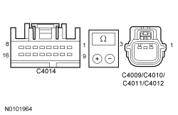 - Are the resistances less than 3 ohms?
| Yes
GO to
B4
.
No
REPAIR the circuit in question.
|
|
B4 CHECK THE REAR SENSOR CIRCUITRY FOR SHORTS TO GROUND
|
|
- Measure the
resistance
between:
| Positive
| Lead
| Negative
| Lead
| | Pin
| Circuit
| Pin
| Circuit
| | DTC B1B44:14
|
|
| | C4011-2
| VMP17 (YE/OG)
| —
| Ground
| | DTC B1B46:14
|
|
| | C4012-2
| VMP16 (YE/GY)
| —
| Ground
| | DTC B1B48:14
|
|
| | C4009-2
| VMP15 (YE/GN)
| —
| Ground
| | DTC B1B50:14
|
|
| | C4010-2
| VMP14 (WH/OG)
| —
| Ground
|
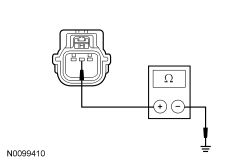 - Are the resistances greater than 10,000 ohms?
| Yes
If all of the parking aid sensors recorded DTCs, GO to
B5
.
If one or more parking aid sensor(s) recorded DTCs, INSTALL a new sensor(s) for the one in question. REFER to
Parking Aid Sensor
.
No
REPAIR the circuit in question.
|
|
B5 CHECK FOR CORRECT
OPERATION
|
|
- Disconnect and inspect the
connector.
- Repair:
- corrosion (install new connector or terminals - clean module pins)
- damaged pins - install new terminals/pins
- pushed-out pins - install new pins as necessary
- Reconnect the
connector. Make sure it seats and latches correctly.
- Operate the system and determine if the concern is still present.
- Is the concern still present?
| Yes
CHECK
for any applicable TSBs. If a TSB exists for this concern, DISCONTINUE this test and FOLLOW TSB instructions. If no TSBs address this concern, INSTALL a new
. REFER to
Parking Aid Module (PAM)
.
No
The system is operating correctly at this time. The concern may have been caused by module connections. ADDRESS the root cause of any connector or pin issues.
|
Pinpoint Test C: DTC B1B44:12, B1B46:12, B1B48:12 Or B1B50:12
Diagnostic Overview
Diagnostics in this manual assume a certain skill level and knowledge of Ford-specific diagnostic practices. Refer to Diagnostic Methods in
Section 100-00
for information about these practices.
Refer to Wiring Diagrams Cell
131
, Parking Aid for schematic and connector information.
Normal Operation and Fault Conditions
The
supplies a reference voltage and signal return to rear parking aid sensors. A fault condition occurs when the
detects a short to voltage on the parking aid sensor signal circuit.
DTC Fault Trigger Conditions
| DTC
| Description
| Fault Trigger Conditions
|
|---|
| B1B44:12
| Right Rear Outer Sensor: Circuit Short To Battery
| A continuous and on-demand DTC that sets when the right rear outer parking aid sensor signal line is shorted to battery voltage.
|
| B1B46:12
| Right Rear Inner Sensor: Circuit Short To Battery
| A continuous and on-demand DTC that sets when the right rear inner parking aid sensor signal line is shorted to battery voltage.
|
| B1B48:12
| Left Rear Outer Sensor: Circuit Short To Battery
| A continuous and on-demand DTC that sets when the left rear outer parking aid sensor signal line is shorted to battery voltage.
|
| B1B50:12
| Left Rear Inner Sensor: Circuit Short To Battery
| A continuous and on-demand DTC that sets when the left rear inner parking aid sensor signal line is shorted to battery voltage.
|
Possible Sources
- Wiring, terminals or connectors
- Parking aid sensor
Visual Inspection and Diagnostic Pre-checks
Before disconnecting the
or the sensors, verify that the connectors are properly seated and latched.
PINPOINT TEST C: DTC B1B44:12, B1B46:12, B1B48:12 OR B1B50:12
NOTICE:
Use the correct probe adapter(s) when making measurements. Failure to use the correct probe adapter(s) may damage the connector.
| Test Step
| Result / Action to Take
|
|---|
|
C1 RETRIEVE THE DTCs FROM BOTH THE CONTINUOUS AND ON-DEMAND
SELF-TESTS
|
|
- Using a scan tool, perform the
self-tests.
- Are multiple DTCs recorded?
| Yes
GO to
C2
.
No
GO to
C3
.
|
|
C2 CHECK THE BUMPER WIRING HARNESS
|
|
- Inspect the bumper wiring harness for opens, shorts, grounds, or corrosion.
- Is the bumper wiring harness OK?
| Yes
GO to
C3
.
No
REPAIR or INSTALL a new bumper wiring harness.
|
|
C3 CHECK THE REAR SENSOR CIRCUITRY FOR SHORTS TO VOLTAGE
|
|
- Ignition OFF.
- Disconnect: Suspect Parking Aid Sensor C4009, C4010, C4011 and/or C4012.
- Disconnect:
C4014.
- Ignition ON.
- Measure the
voltage
between:
| Positive
| Lead
| Negative
| Lead
| | Pin
| Circuit
| Pin
| Circuit
| | DTC B1B44:12
|
|
| | C4011-2
| VMP17 (YE/OG)
| —
| Ground
| | DTC B1B46:12
|
|
| | C4012-2
| VMP16 (YE/GY)
| —
| Ground
| | DTC B1B48:12
|
|
| | C4009-2
| VMP15 (YE/GN)
| —
| Ground
| | DTC B1B50:12
|
|
| | C4010-2
| VMP14 (WH/OG)
| —
| Ground
|
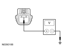 - Is any voltage present?
| Yes
REPAIR the circuit in question.
No
If all sensor DTCs are set, GO to
C5
.
Otherwise, GO to
C4
.
|
|
C4 CHECK THE PARKING AID SENSORS
|
|
- Install a known good parking aid sensor(s) for each of the suspect parking aid sensor(s).
- Using a scan tool, clear the DTCs. Repeat the self-test.
- Test the system for normal operation.
- Is the concern still present?
| Yes
GO to
C5
.
No
If one or more parking aid sensor(s) recorded DTCs, INSTALL a new sensor(s) for the one in question. REFER to
Parking Aid Sensor
.
|
|
C5 CHECK FOR CORRECT
OPERATION
|
|
- Disconnect and inspect the
connector.
- Repair:
- corrosion (install new connector or terminals - clean module pins)
- damaged pins - install new terminals/pins
- pushed-out pins - install new pins as necessary
- Reconnect the
connector. Make sure it seats and latches correctly.
- Operate the system and determine if the concern is still present.
- Is the concern still present?
| Yes
CHECK
for any applicable TSBs. If a TSB exists for this concern, DISCONTINUE this test and FOLLOW TSB instructions. If no TSBs address this concern, INSTALL a new
. REFER to
Parking Aid Module (PAM)
.
No
The system is operating correctly at this time. The concern may have been caused by module connections. ADDRESS the root cause of any connector or pin issues.
|
Pinpoint Test D: DTC B1B44:96, B1B46:96, B1B48:96 Or B1B50:96
Diagnostic Overview
Diagnostics in this manual assume a certain skill level and knowledge of Ford-specific diagnostic practices. Refer to Diagnostic Methods in
Section 100-00
for information about these practices.
Refer to Wiring Diagrams Cell
131
, Parking Aid for schematic and connector information.
Normal Operation and Fault Conditions
Refer to Parking Aid System Operation in
Parking Aid
.
The attenuation time for the rear parking aid sensors is the time required for a sensor to detect the distance to an object expressed in milliseconds (ms). A fault condition occurs when the signal or the attenuation time is out of normal range.
DTC Fault Trigger Conditions
| DTC
| Description
| Fault Trigger Conditions
|
|---|
| B1B44:96
| Right Rear Outer Sensor: Component Internal Failure
| A continuous and on-demand DTC that sets when the right rear outer parking aid sensor has internally failed or has an incorrect attenuation time.
|
| B1B46:96
| Right Rear Inner Sensor: Component Internal Failure
| A continuous and on-demand DTC that sets when the right rear inner parking aid sensor has internally failed or has an incorrect attenuation time.
|
| B1B48:96
| Left Rear Outer Sensor: Component Internal Failure
| A continuous and on-demand DTC that sets when the left rear outer parking aid sensor has internally failed or has an incorrect attenuation time.
|
| B1B50:96
| Left Rear Inner Sensor: Component Internal Failure
| A continuous and on-demand DTC that sets when the left rear inner parking aid sensor has internally failed or has an incorrect attenuation time.
|
Possible Sources
- Wiring, terminals or connectors
- Parking aid sensor
PINPOINT TEST D: DTC B1B44:96, B1B46:96, B1B48:96 OR B1B50:96
| Test Step
| Result / Action to Take
|
|---|
|
D1 CHECK THE DTCs FROM BOTH THE CONTINUOUS AND ON-DEMAND
SELF-TESTS
|
|
- Using a scan tool, perform the
self-tests.
- Are parking aid DTCs other than B1B44:96, B1B46:96, B1B48:96 or B1B50:96 recorded?
| Yes
DIAGNOSE the other DTCs first. REFER to DTC Charts in this section.
No
GO to
D2
.
|
|
D2 CHECK THE PARKING AID SENSOR OPERATION
|
|
NOTE:
Make sure the area around the vehicle is clear of anything that might activate the parking aid system.
- Clean the bumper and sensors with high-pressure water.
- Perform the azimuth system check. Refer to
Azimuth System Check
.
- Perform the elevation system check. Refer to
Elevation System Check
.
- Does the parking aid system pass both system checks?
| Yes
The system is operating correctly at this time. The concern may have been caused by a dirty or blocked parking aid sensor.
No
GO to
D3
.
|
|
D3 INSTALL A KNOWN GOOD SENSOR
|
|
- Install a known good sensor for the suspect parking aid sensor.
- Ignition ON.
- Using a scan tool, clear the DTCs. Repeat the self-test. Operate the system and verify the concern is still present.
- Is the concern still present?
| Yes
GO to
D4
.
No
INSTALL a new parking aid sensor. REFER to
Parking Aid Sensor
.
|
|
D4 CHECK FOR CORRECT
OPERATION
|
|
- Disconnect and inspect the
connector.
- Repair:
- corrosion (install new connector or terminals - clean module pins)
- damaged pins - install new terminals/pins
- pushed-out pins - install new pins as necessary
- Reconnect the
connector. Make sure it seats and latches correctly.
- Operate the system and determine if the concern is still present.
- Is the concern still present?
| Yes
CHECK
for any applicable TSBs. If a TSB exists for this concern, DISCONTINUE this test and FOLLOW TSB instructions. If no TSBs address this concern, INSTALL a new
. REFER to
Parking Aid Module (PAM)
.
No
The system is operating correctly at this time. The concern may have been caused by module connections. ADDRESS the root cause of any connector or pin issues.
|
Pinpoint Test E: DTC B1B52:12 Or DTC B1B52:14
Diagnostic Overview
Diagnostics in this manual assume a certain skill level and knowledge of Ford-specific diagnostic practices. Refer to Diagnostic Methods in
Section 100-00
for information about these practices.
Refer to Wiring Diagrams Cell
131
, Parking Aid for schematic and connector information.
Normal Operation and Fault Conditions
DTC Fault Trigger Conditions
| DTC
| Description
| Fault Trigger Conditions
|
|---|
| B1B52:12
| Rear Sounder-Park Aid: Circuit Short To Battery
| Sets when the sounder circuit is shorted to voltage.
|
| B1B52:14
| Rear Sounder-Park Aid: Circuit Short To Ground Or Open
| Sets when the sounder circuit is open or shorted to ground.
|
Possible Sources
- Wiring, terminals or connectors
- Rear parking aid speaker
Visual Inspection and Diagnostic Pre-checks
Before disconnecting the
or the sensors, verify that the connectors are properly seated and latched.
PINPOINT TEST E: DTC B1B52:12 OR DTC B1B52:14
NOTICE:
Use the correct probe adapter(s) when making measurements. Failure to use the correct probe adapter(s) may damage the connector.
| Test Step
| Result / Action to Take
|
|---|
|
E1 CHECK THE SPEAKER CONNECTOR FOR CORRECT LATCHING
|
|
- Ignition OFF.
- Inspect the parking aid speaker connector C4015 for correct latching by pulling on the latched connector.
- Is the connector latched?
| Yes
GO to
E2
.
No
Correctly latch the connector.
|
|
E2 MEASURE THE PARKING AID SPEAKER RESISTANCE
|
|
- Disconnect: Rear Parking Aid Speaker C4015.
- Measure the
component side resistance
between:
| Positive
| Lead
| Negative
| Lead
| | Pin
| Circuit
| Pin
| Circuit
| | C4015 pin 2
| —
| C4015 pin 1
| —
|
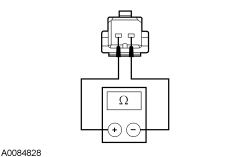 - Is the resistance between 40 and 60 ohms?
| Yes
If DTC B1B52:14 was recorded, GO to
E3
.
If DTC B1B52:12 was recorded, GO to
E6
.
No
INSTALL a new parking aid speaker. REFER to
Parking Aid Module (PAM)
.
|
|
E3 CHECK THE REAR PARKING AID SPEAKER CIRCUITS FOR A SHORT TO GROUND
|
|
- Disconnect:
C4014.
- Measure the
resistance
between:
| Positive
| Lead
| Negative
| Lead
| | Pin
| Circuit
| Pin
| Circuit
| | C4014-2
| CMP09 (BN/BU)
| —
| Ground
| | C4014-6
| RMP09 (BU/GN)
| —
| Ground
|
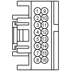 - Are the resistances greater than 10,000 ohms?
| Yes
GO to
E4
.
No
REPAIR the circuit in question.
|
|
E4 CHECK THE REAR PARKING AID SPEAKER CIRCUITS FOR AN OPEN
|
|
- Measure the
resistance
between:
| Positive
| Lead
| Negative
| Lead
| | Pin
| Circuit
| Pin
| Circuit
| | C4014-2
| CMP09 (BN/BU)
| C4015-2
| CMP09 (BN/BU)
| | C4014-6
| RMP09 (BU/GN)
| C4015-1
| RMP09 (BU/GN)
|
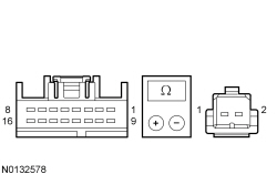 - Are the resistances less than 3 ohms?
| Yes
GO to
E5
.
No
REPAIR the circuit in question.
|
|
E5 CHECK THE PARKING AID SPEAKER CIRCUITS FOR A SHORT TO EACH OTHER
|
|
- Measure the
resistance
between:
| Positive
| Lead
| Negative
| Lead
| | Pin
| Circuit
| Pin
| Circuit
| | C4014-2
| CMP09 (BN/BU)
| C4014-6
| RMP09 (BU/GN)
|
 - Is the resistance greater than 10,000 ohms?
| Yes
GO to
E7
.
No
REPAIR the circuits.
|
|
E6 CHECK THE PARKING AID SPEAKER CIRCUITRY FOR A SHORT TO VOLTAGE
|
|
- Disconnect:
C4014.
- Ignition ON.
- Measure the
voltage
between:
| Positive
| Lead
| Negative
| Lead
| | Pin
| Circuit
| Pin
| Circuit
| | C4014-2
| CMP09 (BN/BU)
| —
| Ground
| | C4014-6
| RMP09 (BU/GN)
| —
| Ground
|
 - Is any voltage present?
| Yes
REPAIR the circuit in question.
No
GO to
E7
.
|
|
E7 CHECK FOR CORRECT
OPERATION
|
|
- Disconnect and inspect the
connector.
- Repair:
- corrosion (install new connector or terminals - clean module pins)
- damaged pins - install new terminals/pins
- pushed-out pins - install new pins as necessary
- Reconnect the
connector. Make sure it seats and latches correctly.
- Operate the system and determine if the concern is still present.
- Is the concern still present?
| Yes
CHECK
for any applicable TSBs. If a TSB exists for this concern, DISCONTINUE this test and FOLLOW TSB instructions. If no TSBs address this concern, INSTALL a new
. REFER to
Parking Aid Module (PAM)
.
No
The system is operating correctly at this time. The concern may have been caused by module connections. ADDRESS the root cause of any connector or pin issues.
|
Pinpoint Test F: DTC B1B58:11
Diagnostic Overview
Diagnostics in this manual assume a certain skill level and knowledge of Ford-specific diagnostic practices. Refer to Diagnostic Methods in
Section 100-00
for information about these practices.
Refer to Wiring Diagrams Cell
131
, Parking Aid for schematic and connector information.
Normal Operation and Fault Conditions
DTC Fault Trigger Conditions
| DTC
| Description
| Fault Trigger Conditions
|
|---|
| B1B58:11
| Rear Sensors Power Circuit: Circuit Short to Ground
| Sets when the sensor voltage supply circuit is shorted to ground or to the signal return circuit.
|
Possible Sources
- Wiring, terminals or connectors
- Parking aid sensor
Visual Inspection and Diagnostic Pre-checks
Before disconnecting the
or the sensors, verify that the connectors are properly seated and latched.
PINPOINT TEST F: DTC B1B58:11
NOTICE:
Use the correct probe adapter(s) when making measurements. Failure to use the correct probe adapter(s) may damage the connector.
| Test Step
| Result / Action to Take
|
|---|
|
F1 CHECK THE BUMPER WIRING HARNESS
|
|
- Inspect the bumper wiring harness for opens, shorts, grounds, or corrosion.
- Is the bumper wiring harness OK?
| Yes
GO to
F2
.
No
REPAIR or INSTALL a new bumper wiring harness.
|
|
F2 CHECK THE REAR LH OUTER SENSOR FOR AN INTERNAL SHORT
|
|
| Yes
GO to
F3
.
No
INSTALL a new rear LH outer parking aid sensor. REFER to
Parking Aid Sensor
.
|
|
F3 CHECK THE REAR RH OUTER SENSOR FOR AN INTERNAL SHORT
|
|
| Yes
GO to
F4
.
No
INSTALL a new rear RH outer parking aid sensor. REFER to
Parking Aid Sensor
.
|
|
F4 CHECK THE REAR LH INNER SENSOR FOR AN INTERNAL SHORT
|
|
| Yes
GO to
F5
.
No
INSTALL a new rear LH inner parking aid sensor. REFER to
Parking Aid Sensor
.
|
|
F5 CHECK THE REAR RH INNER SENSOR FOR AN INTERNAL SHORT
|
|
| Yes
For vehicles equipped with active park assist, GO to
F6
.
Otherwise, GO to
F8
.
No
INSTALL a new rear RH inner parking aid sensor. REFER to
Parking Aid Sensor
.
|
|
F6 CHECK THE ACTIVE PARK ASSIST SENSOR RIGHT FOR AN INTERNAL SHORT
|
|
- Ignition OFF.
- Disconnect: Active Park Assist Sensor Right C1431.
- Ignition ON.
- Using a scan tool, clear the DTCs. Repeat the on-demand self-test.
- Is DTC B1B58:11 still present?
| Yes
GO to
F7
.
No
INSTALL a new active park assist sensor right. REFER to
Section 413-13C
.
|
|
F7 CHECK THE ACTIVE PARK ASSIST SENSOR LEFT FOR AN INTERNAL SHORT
|
|
- Ignition OFF.
- Disconnect: Active Park Assist Sensor Left C1428.
- Ignition ON.
- Using a scan tool, clear the DTCs. Repeat the on-demand self-test.
- Is DTC B1B58:11 still present?
| Yes
GO to
F8
.
No
INSTALL a new active park assist sensor left. REFER to
Section 413-13C
.
|
|
F8 CHECK THE REAR PARKING AID SENSORS VOLTAGE SUPPLY CIRCUIT FOR A SHORT TO GROUND
|
|
- Ignition OFF.
- Disconnect:
C4014.
- Measure the
resistance
between:
| Positive
| Lead
| Negative
| Lead
| | Pin
| Circuit
| Pin
| Circuit
| | C4014-9
| LMP07 (BU/WH) or (BU)
| —
| Ground
|
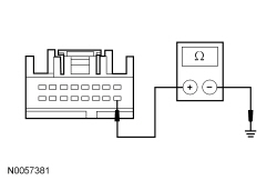 - Is the resistance greater than 10,000 ohms?
| Yes
GO to
F9
.
No
REPAIR the circuit in question.
|
|
F9 CHECK THE REAR PARKING AID SENSORS VOLTAGE SUPPLY CIRCUIT FOR A SHORT TO THE REAR PARKING AID SENSORS GROUND CIRCUIT
|
|
- Ignition OFF.
- Measure the
resistance
between:
| Positive
| Lead
| Negative
| Lead
| | Pin
| Circuit
| Pin
| Circuit
| | C4014-12
| RMP07 (GN/WH) or (GN)
| C4014-9
| LMP07 (BU/WH) or (BU)
|
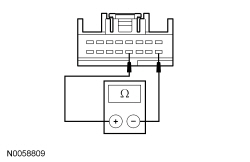 - Is the resistance greater than 10,000 ohms?
| Yes
GO to
F10
.
No
REPAIR the circuit in question.
|
|
F10 CHECK FOR CORRECT
OPERATION
|
|
- Disconnect and inspect the
connector.
- Repair:
- corrosion (install new connector or terminals - clean module pins)
- damaged pins - install new terminals/pins
- pushed-out pins - install new pins as necessary
- Reconnect the
connector. Make sure it seats and latches correctly.
- Operate the system and determine if the concern is still present.
- Is the concern still present?
| Yes
CHECK
for any applicable TSBs. If a TSB exists for this concern, DISCONTINUE this test and FOLLOW TSB instructions. If no TSBs address this concern, INSTALL a new
. REFER to
Parking Aid Module (PAM)
.
No
The system is operating correctly at this time. The concern may have been caused by module connections. ADDRESS the root cause of any connector or pin issues.
|
Pinpoint Test G: The Audio Output Does Not Reduce When The Parking Aid Tone Sounds
Diagnostic Overview
Diagnostics in this manual assume a certain skill level and knowledge of Ford-specific diagnostic practices. Refer to Diagnostic Methods in
Section 100-00
for information about these practices.
Normal Operation and Fault Conditions
Refer to Parking Aid Audible Alert in
Parking Aid
.
Possible Sources
- Wiring, terminals or connectors
PINPOINT TEST G: THE AUDIO OUTPUT DOES NOT REDUCE WHEN THE PARKING AID TONE SOUNDS
| Test Step
| Result / Action to Take
|
|---|
|
G1 CHECK FOR CORRECT PARKING AID SYSTEM OPERATION
|
|
- Apply the parking brake.
- Place an object behind the vehicle within the range of the parking aid sensors.
- Ignition ON.
- Place the transmission in REVERSE (R).
- Verify the parking aid tone is sounding and the
volume is reduced.
- Is the parking aid tone sounding and
volume reduced?
| Yes
The system is operating correctly at this time. The
volume cutback may have faulted due to high network traffic or an intermittent fault condition.
No
GO to
G2
.
|
|
G2 CHECK THE PARKING AID SIGNAL
|
|
- Apply the parking brake.
- Place an object behind the vehicle within the range of the parking aid sensors.
- Ignition ON.
- Place the transmission in REVERSE (R).
- Using a scan tool, view
PIDs.
- Monitor the parking aid input status PID (RPA_STAT) while the parking aid tone is sounding.
- Does the PID read "Enabled" while the parking aid tone is sounding?
| Yes
GO to
G4
.
No
GO to
G3
.
|
|
G3 CHECK FOR COMMUNICATION WITH THE
|
|
- Using a scan tool, perform the network test.
- Does the scan tool communicate with the
?
| Yes
GO to
G4
.
No
REFER to
Section 418-00
to diagnose no communication with the
.
|
|
G4 CHECK FOR CORRECT
OPERATION
|
|
- Disconnect and inspect all the
connectors.
- Repair:
- corrosion (install new connector or terminals - clean module pins)
- damaged pins - install new terminals/pins
- pushed-out pins - install new pins as necessary
- Reconnect the
connectors. Make sure they seat and latch correctly.
- Operate the system and determine if the concern is still present.
- Is the concern still present?
| Yes
CHECK
for any applicable TSBs. If a TSB exists for this concern, DISCONTINUE this test and FOLLOW TSB instructions. If no TSBs address this concern, INSTALL a new
. Refer to the appropriate section in Group
415
for the procedure.
No
The system is operating correctly at this time. The concern may have been caused by module connections. ADDRESS the root cause of any connector or pin issues.
|


