SECTION 417-02: Interior Lighting
| 2014 Flex Workshop Manual
|
DIAGNOSIS AND TESTING
| Procedure revision date: 05/02/2013
|
Interior Lighting
Charts
Diagnostics in this manual assume a certain skill level and knowledge of Ford-specific diagnostic practices. Refer to Diagnostic Methods in
Section 100-00
for information about these practices.
Chart
HVAC Module
Chart
Chart
Symptom Chart
Diagnostics in this manual assume a certain skill level and knowledge of Ford-specific diagnostic practices. Refer to Diagnostic Methods in
Section 100-00
for information about these practices.
Symptom Chart
| Condition
| Possible Sources
| Action
|
|---|
- A module does not respond to the scan tool
| - Fuse
- Wiring, terminals or connectors
- Module
| |
- The courtesy lamps flash on and off
| - The
is not configured correctly
| - This symptom is present due to incomplete or improper
procedures. REPEAT/PERFORM the
procedure as directed by the scan tool. REFER to
Section 418-01
.
|
- The courtesy lamps do not illuminate with a door open
| - Refer to the Pinpoint Test
| |
- The courtesy lamps do not illuminate from the instrument panel dimmer switch
| - Refer to the Pinpoint Test
| |
- The Courtesy Lamps Do Not Illuminate With The Liftgate Open
| - Refer to the Pinpoint Test
| |
- One or more interior courtesy lamp is inoperative
| - Refer to the Pinpoint Test
| |
- One or more puddle lamp is inoperative
| - Refer to the Pinpoint Test
| |
- All the courtesy lamps stay on continuously
| - Refer to the Pinpoint Test
| |
- The puddle lamps stay on continuously
| - Refer to the Pinpoint Test
| |
- The interior courtesy lamps stay on continuously
| - Refer to the Pinpoint Test
| |
- All the demand lamps are inoperative
| - Refer to the Pinpoint Test
| |
- An individual demand lamp is inoperative
| - Refer to the Pinpoint Test
| |
- The battery saver does not deactivate after time-out
| - Refer to the Pinpoint Test
| |
- One or more of the ambient lighting
are inoperative
| - Refer to the Pinpoint Test
| |
- One or more of the ambient lighting
do not cycle through all color combinations
| - Refer to the Pinpoint Test
| |
Pinpoint Tests
Pinpoint Test A: The Courtesy Lamps Do Not Illuminate With A Door Open
Diagnostic Overview
Diagnostics in this manual assume a certain skill level and knowledge of Ford-specific diagnostic practices. Refer to Diagnostic Methods in
Section 100-00
for information about these practices.
Refer to Wiring Diagrams Cell
89
, Interior Lamps for schematic and connector information.
Normal Operation and Fault Conditions
Refer to Courtesy Lamps in
Interior Lighting
.
Possible Sources
- Wiring, terminals or connectors
- Door latch
PINPOINT TEST A: THE COURTESY LAMPS DO NOT ILLUMINATE WITH A DOOR OPEN
NOTE:
Make sure that the dark car feature is not enabled in the
. The dark car feature disables activation of courtesy lamps due to a door unlock, door ajar or removing the key from the ignition cylinder. The feature can be disabled using a scan tool.
| Test Step
| Result / Action to Take
|
|---|
|
A1 CHECK THE COURTESY LAMP OPERATION USING THE INSTRUMENT PANEL DIMMER SWITCH
|
|
- Press and hold the instrument panel dimmer switch to the DOME LAMP ON (second detent up) position for 3 seconds.
- Do the interior courtesy lamps illuminate using the instrument panel dimmer switch?
| Yes
GO to
A2
.
No
GO to Pinpoint Test C
.
|
|
A2 CHECK THE DOOR AJAR SWITCH OPERATION
|
|
- Press and hold the instrument panel dimmer switch to the DOME LAMP OFF (second detent down) position for 3 seconds.
- Disconnect: Suspect Door Latch.
- Do the interior lamps illuminate?
| Yes
INSTALL a new door latch in question. REFER to
Section 501-14A
(without
) or
Section 501-14B
(with
).
No
GO to
A3
.
|
|
A3 CHECK THE SUSPECT DOOR AJAR SWITCH CIRCUIT FOR A SHORT TO GROUND
|
|
- Disconnect:
C2280C.
- Measure the
resistance
between:
| Positive Lead
| Negative Lead
| | Pin
| Circuit
| Pin
| Circuit
| | LH Front Door Ajar Switch
| | C525-5
| CPL26 (GN/VT)
| —
| Ground
| | RH Front Door Ajar Switch
| | C603-5
| CPL31 (WH)
| —
| Ground
| | LH Rear Door Ajar Switch
| | C704-5
| CPL39 (YE)
| —
| Ground
| | RH Rear Door Ajar Switch
| | C804-5
| CPL39 (YE)
| —
| Ground
|
 - Is the resistance greater than 10,000 ohms?
| Yes
GO to
A4
.
No
REPAIR the circuit.
|
|
A4 CHECK FOR CORRECT
OPERATION
|
|
- Disconnect and inspect all the
connectors.
- Repair:
- corrosion (install new connector or terminals – clean module pins)
- damaged or bent pins – install new terminals/pins
- pushed-out pins – install new pins as necessary
- Reconnect the
connectors. Make sure they seat and latch correctly.
- Operate the system and determine if the concern is still present.
- Is the concern still present?
| Yes
CHECK On-Line Automotive Service Information System (OASIS) for any applicable TSBs. If a TSB exists for this concern, DISCONTINUE this test and FOLLOW TSB instructions. If no TSBs address this concern, INSTALL a new
. REFER to
Section 419-10
.
No
The system is operating correctly at this time. The concern may have been caused by module connections. ADDRESS the root cause of any connector or pin issues.
|
Pinpoint Test B: The Courtesy Lamps Do Not Illuminate From The Instrument Panel Dimmer Switch
Diagnostic Overview
Diagnostics in this manual assume a certain skill level and knowledge of Ford-specific diagnostic practices. Refer to Diagnostic Methods in
Section 100-00
for information about these practices.
Refer to Wiring Diagrams Cell
89
, Interior Lamps for schematic and connector information.
Normal Operation and Fault Conditions
Refer to Courtesy Lamps in
Interior Lighting
.
Possible Sources
- Wiring, terminals or connectors
- Instrument panel dimmer switch
PINPOINT TEST B: THE COURTESY LAMPS DO NOT ILLUMINATE FROM THE INSTRUMENT PANEL DIMMER SWITCH
| Test Step
| Result / Action to Take
|
|---|
|
B1 CHECK THE OPERATION OF THE COURTESY LAMPS FROM A DOOR
|
|
- Place the headlamp switch in the OFF position.
- Open any door and observe the interior courtesy lamps.
- Do the interior courtesy lamps illuminate?
| Yes
GO to
B2
.
No
GO to Pinpoint Test A
.
|
|
B2 CHECK THE DIMMABLE BACKLIGHTING ILLUMINATION
|
|
- Turn the headlamps switch to the PARKING LAMPS ON position.
- Monitor the instrument panel dimmable backlighting while pressing (and holding) the instrument panel dimmer switch to the first detent up and then the first detent down.
- Does the instrument cluster illumination intensity change with the instrument panel dimmer switch position?
| Yes
GO to
B3
.
No
REFER to
Section 413-00
to continue diagnosis of the dimmable backlighting illumination.
|
|
B3 CHECK FOR A VOLTAGE SIGNAL TO THE INSTRUMENT PANEL DIMMER SWITCH
|
|
- Ignition OFF.
- Turn the headlamps switch to the OFF position.
- Disconnect: Instrument Panel Dimmer Switch C2065.
- Measure the
voltage
between:
| Positive Lead
| Negative Lead
| | Pin
| Circuit
| Pin
| Circuit
| | C2065-2
| VLN36 (GY/OG)
| —
| Ground
|
 - Is the voltage approximately 5 volts?
| Yes
INSTALL a new instrument panel dimmer switch. REFER to
Section 413-00
.
No
GO to
B4
.
|
|
B4 CHECK THE DOME LAMP REQUEST INPUT CIRCUIT FOR AN OPEN
|
|
- Disconnect:
C2414A.
- Measure the
resistance
between:
| Positive Lead
| Negative Lead
| | Pin
| Circuit
| Pin
| Circuit
| | C2414A-19
| VLN36 (GY/OG)
| C2065-2
| VLN36 (GY/OG)
|
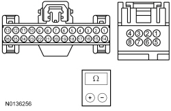 - Is the resistance less than 3 ohms?
| Yes
GO to
B5
.
No
REPAIR the circuit.
|
|
B5 CHECK FOR CORRECT
OPERATION
|
|
- Disconnect and inspect all the
connectors.
- Repair:
- corrosion (install new connector or terminals – clean module pins)
- damaged or bent pins – install new terminals/pins
- pushed-out pins – install new pins as necessary
- Reconnect the
connectors. Make sure they seat and latch correctly.
- Operate the system and determine if the concern is still present.
- Is the concern still present?
| Yes
CHECK On-Line Automotive Service Information System (OASIS) for any applicable TSBs. If a TSB exists for this concern, DISCONTINUE this test and FOLLOW TSB instructions. If no TSBs address this concern, INSTALL a new
. REFER to
Section 211-05
.
No
The system is operating correctly at this time. The concern may have been caused by module connections. ADDRESS the root cause of any connector or pin issues.
|
Pinpoint Test C: One Or More Interior Courtesy Lamp Is Inoperative
Diagnostic Overview
Diagnostics in this manual assume a certain skill level and knowledge of Ford-specific diagnostic practices. Refer to Diagnostic Methods in
Section 100-00
for information about these practices.
Refer to Wiring Diagrams Cell
89
, Interior Lamps for schematic and connector information.
Normal Operation and Fault Conditions
Refer to Courtesy Lamps in
Interior Lighting
.
DTC Fault Trigger Conditions
| DTC
| Description
| Fault Trigger Conditions
|
|---|
| B1313:11
| Interior Lighting Output: Circuit Short To Ground
| Sets when the
detects a short to ground from the courtesy lighting output circuit.
|
| B1313:15
| Interior Lighting Output: Circuit Short To Battery or Open
| Sets when the
detects an open from the courtesy lighting output circuit.
|
Possible Sources
- fuse 12 (15A)
- Wiring, terminals or connectors
- Interior lamp
PINPOINT TEST C: ONE OR MORE INTERIOR COURTESY LAMP IS INOPERATIVE
NOTE:
After any repair:
If
DTC U1000:00 is present, clear the DTCs and repeat the self-test (required to enable the low beam output driver if DTC U1000:00 is present).
If
DTC U3000:49 is present, install a new
. Refer to
Section 419-10
.
| Test Step
| Result / Action to Take
|
|---|
|
C1 CHECK THE OPERATION OF ALL THE INTERIOR COURTESY LAMPS
|
|
- Ignition OFF.
- Press and hold the instrument panel dimmer switch to the DOME LAMP ON (second detent up) position for 3 seconds.
- Are all the interior courtesy lamps inoperative?
| Yes
VERIFY
fuse 12 (15A) is OK. If OK, GO to
C4
. If not OK, REFER to the Wiring Diagrams manual to identify the possible causes of the circuit short.
No
GO to
C2
.
|
|
C2 CHECK FOR VOLTAGE TO THE INTERIOR LAMP
|
|
- Turn the interior courtesy lamps off.
- Disconnect: Inoperative Lamp.
- Press and hold the instrument panel dimmer switch to the DOME LAMP ON (second detent up) position for 3 seconds.
- For front interior lamp, measure the
voltage
between:
| Positive Lead
| Negative Lead
| | Pin
| Circuit
| Pin
| Circuit
| | C929-2
| VLN33 (GY/VT)
| —
| Ground
|
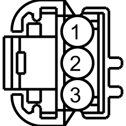
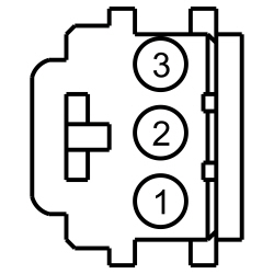 - For second row interior lamp (with roof opening panel), measure the
voltage
between:
| Positive Lead
| Negative Lead
| | Pin
| Circuit
| Pin
| Circuit
| | LH Second Row Lamp
| | C9009-1
| VLN33 (GY/VT)
| —
| Ground
| | RH Second Row Lamp
| | C9010-1
| VLN33 (GY/VT)
| —
| Ground
|
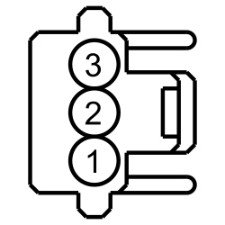
 - For second row (without roof opening panel) and third row interior lamp, measure the
voltage
between:
| Positive Lead
| Negative Lead
| | Pin
| Circuit
| Pin
| Circuit
| | Second Row Lamp
| | C961-1
| VLN33 (GY/VT)
| —
| Ground
| | Third Row Lamp
| | C932-1
| VLN33 (GY/VT)
| —
| Ground
|
 - Is the voltage greater than 11 volts?
| Yes
GO to
C3
.
No
REPAIR the circuit.
|
|
C3 CHECK THE INTERIOR LAMP GROUND CIRCUIT FOR AN OPEN
|
|
- For front interior lamp, measure the
voltage
between:
| Positive Lead
| Negative Lead
| | Pin
| Circuit
| Pin
| Circuit
| | C929-2
| VLN33 (GY/VT)
| C929-1
| GD233 (BK)
|
 - For second row interior lamp (with roof opening panel), measure the
voltage
between:
| Positive Lead
| Negative Lead
| | Pin
| Circuit
| Pin
| Circuit
| | LH Second Row Lamp
| | C9009-1
| VLN33 (GY/VT)
| C9009-2
| GD233 (BK)
| | RH Second Row Lamp
| | C9010-1
| VLN33 (GY/VT)
| C9010-2
| GD233 (BK)
|
 - For second row (without roof opening panel) and third row interior lamp, measure the
voltage
between:
| Positive Lead
| Negative Lead
| | Pin
| Circuit
| Pin
| Circuit
| | Second Row Lamp
| | C961-1
| VLN33 (GY/VT)
| C961-2
| GD233 (BK)
| | Third Row Lamp
| | C932-1
| VLN33 (GY/VT)
| C932-2
| GD233 (BK)
|
 - Is the voltage greater than 11 volts?
| Yes
INSTALL a new interior lamp for the lamp in question. REFER to
Interior Lamp
.
No
REPAIR the circuit.
|
|
C4 BYPASS THE
|
|
- Ignition OFF.
- Disconnect:
C2280A.
- Connect a
fused jumper wire
between:
| Lead 1
| Lead 2
| | Pin
| Circuit
| Pin
| Circuit
| | C2280A-1
| VLN33 (GY/VT)
| —
| Battery positive
|
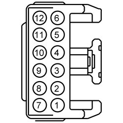 - Do the courtesy lamps illuminate?
| Yes
REMOVE the jumper wire. GO to
C5
.
No
REMOVE the jumper wire. REPAIR the circuit.
|
|
C5 CHECK FOR CORRECT
OPERATION
|
|
- Disconnect and inspect all the
connectors.
- Repair:
- corrosion (install new connector or terminals – clean module pins)
- damaged or bent pins – install new terminals/pins
- pushed-out pins – install new pins as necessary
- Reconnect the
connectors. Make sure they seat and latch correctly.
- Operate the system and determine if the concern is still present.
- Is the concern still present?
| Yes
CHECK On-Line Automotive Service Information System (OASIS) for any applicable TSBs. If a TSB exists for this concern, DISCONTINUE this test and FOLLOW TSB instructions. If no TSBs address this concern, INSTALL a new
. REFER to
Section 419-10
.
No
The system is operating correctly at this time. The concern may have been caused by module connections. ADDRESS the root cause of any connector or pin issues.
|
Pinpoint Test D: One Or More Puddle Lamp Is Inoperative
Diagnostic Overview
Diagnostics in this manual assume a certain skill level and knowledge of Ford-specific diagnostic practices. Refer to Diagnostic Methods in
Section 100-00
for information about these practices.
Refer to Wiring Diagrams Cell
89
, Interior Lamps for schematic and connector information.
Normal Operation and Fault Conditions
Refer to Courtesy Lamps in
Interior Lighting
.
DTC Fault Trigger Conditions
| DTC
| Description
| Fault Trigger Conditions
|
|---|
| B12C2:11
| Puddle Lamp: Circuit Short To Ground
| Sets when the
detects a short to ground from the puddle lamp output circuit.
|
Possible Sources
- fuse 12 (15A)
- Wiring, terminals or connectors
- Puddle lamp
- Exterior mirror
PINPOINT TEST D: ONE OR MORE PUDDLE LAMP IS INOPERATIVE
NOTE:
After any repair:
If
DTC U1000:00 is present, clear the DTCs and repeat the self-test (required to enable the low beam output driver if DTC U1000:00 is present).
If
DTC U3000:49 is present, install a new
. Refer to
Section 419-10
.
| Test Step
| Result / Action to Take
|
|---|
|
D1 DETERMINE IF BOTH PUDDLE LAMPS ARE INOPERATIVE
|
|
- Ignition OFF.
- Press and hold the instrument panel dimmer switch to the DOME LAMP ON (second detent up) position for 3 seconds.
- Are both the puddle lamps inoperative?
| Yes
VERIFY
fuse 12 (15A) is OK. If OK, GO to
D4
. If not OK, REFER to the Wiring Diagrams manual to identify the possible causes of the circuit short.
No
GO to
D2
.
|
|
D2 CHECK FOR VOLTAGE TO THE EXTERIOR MIRROR
|
|
- Press and hold the instrument panel dimmer switch to the DOME LAMP OFF (second detent down) position for 3 seconds.
- Disconnect: LH Exterior Mirror C516 or RH Exterior Mirror C625.
- Press and hold the instrument panel dimmer switch to the DOME LAMP ON (second detent up) position for 3 seconds.
- Measure the
voltage
between:
| Positive Lead
| Negative Lead
| | Pin
| Circuit
| Pin
| Circuit
| | LH Puddle Lamp
| | C516-5
| CLN25 (VT)
| —
| Ground
| | RH Puddle Lamp
| | C625-5
| CLN25 (VT)
| —
| Ground
|
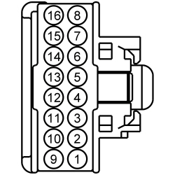 - Is the voltage greater than 11 volts?
| Yes
GO to
D3
.
No
REPAIR the circuit.
|
|
D3 CHECK THE EXTERIOR MIRROR GROUND CIRCUIT FOR AN OPEN
|
|
- Measure the
voltage
between:
| Positive Lead
| Negative Lead
| | Pin
| Circuit
| Pin
| Circuit
| | LH Puddle Lamp
| | C516-5
| CLN25 (VT)
| C516-7
| GD233 (BK)
| | RH Puddle Lamp
| | C625-5
| CLN25 (VT)
| C625-7
| GD348 (BK/YE)
|
 - Is the voltage greater than 11 volts?
| Yes
CHECK the inoperative exterior mirror jumper harness between the vehicle harness and the exterior mirror motor for open circuits and damaged or pushed-out pins. If the jumper harness is not OK, REPAIR the jumper harness. If the jumper harness cannot be repaired, INSTALL a new exterior mirror in question. REFER to
Section 501-09
.
No
REPAIR the circuit.
|
|
D4 BYPASS THE
|
|
- Press and hold the instrument panel dimmer switch to the DOME LAMP OFF (second detent down) position for 3 seconds.
- Disconnect:
C2280C.
- Connect a
fused jumper wire
between:
| Lead 1
| Lead 2
| | Pin
| Circuit
| Pin
| Circuit
| | C2280C-1
| CLN25 (VT)
| —
| Battery positive
|
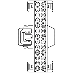 - Do the puddle lamps illuminate?
| Yes
REMOVE the jumper wire. GO to
D5
.
No
REMOVE the jumper wire. REPAIR the circuit.
|
|
D5 CHECK FOR CORRECT
OPERATION
|
|
- Disconnect and inspect all the
connectors.
- Repair:
- corrosion (install new connector or terminals – clean module pins)
- damaged or bent pins – install new terminals/pins
- pushed-out pins – install new pins as necessary
- Reconnect the
connectors. Make sure they seat and latch correctly.
- Operate the system and determine if the concern is still present.
- Is the concern still present?
| Yes
CHECK On-Line Automotive Service Information System (OASIS) for any applicable TSBs. If a TSB exists for this concern, DISCONTINUE this test and FOLLOW TSB instructions. If no TSBs address this concern, INSTALL a new
. REFER to
Section 419-10
.
No
The system is operating correctly at this time. The concern may have been caused by module connections. ADDRESS the root cause of any connector or pin issues.
|
Pinpoint Test E: All The Courtesy Lamps Stay On Continuously
Diagnostic Overview
Diagnostics in this manual assume a certain skill level and knowledge of Ford-specific diagnostic practices. Refer to Diagnostic Methods in
Section 100-00
for information about these practices.
Refer to Wiring Diagrams Cell
89
, Interior Lamps for schematic and connector information.
Refer to Wiring Diagrams Cell
117
, Remote Keyless Entry and Alarm for schematic and connector information.
Normal Operation and Fault Conditions
Refer to Courtesy Lamps in
Interior Lighting
.
DTC Fault Trigger Conditions
| DTC
| Description
| Fault Trigger Conditions
|
|---|
| B1175:01
| Driver Door Ajar Switch: General Electrical Failure
| A continuous and on-demand DTC that sets when the
module detects an open from the LH front door ajar circuit.
|
| B1176:01
| Passenger Door Ajar Switch: General Electrical Failure
| A continuous and on-demand DTC that sets when the
module detects an open from the RH front door ajar circuit.
|
| B11C0:01
| Driver Side Rear Door Ajar Switch: General Electrical Failure
| A continuous and on-demand DTC that sets when the
module detects an open from the LH rear door ajar circuit.
|
| B11C1:01
| Passenger Side Rear Door Ajar Switch: General Electrical Failure
| A continuous and on-demand DTC that sets when the
module detects an open from the RH rear door ajar circuit.
|
| B2718
| Liftgate/Decklid Ajar Output Short to Battery
| Sets when the
detects a short to voltage from the liftgate ajar circuit to the
.
|
| B2721
| Liftgate/Decklid Ajar Output Short to Ground or Open
| Sets when the
detects an open from the liftgate ajar circuit to the
.
|
| B1306:01
| Liftgate Ajar Switch: General Electrical Failure
| A continuous and on-demand DTC that sets when the
module detects an open from the liftgate ajar circuit.
|
Possible Sources
- Wiring, terminals or connectors
- Door ajar switch
- Liftgate ajar switch
PINPOINT TEST E: ALL THE COURTESY LAMPS STAY ON CONTINUOUSLY
| Test Step
| Result / Action to Take
|
|---|
|
E1 CHECK THE DOOR AJAR SWITCH PIDs
|
|
- Ignition ON.
- Using a scan tool, monitor the
ajar switch PIDs (DOOR_SW_LUGG, DOOR_SW_DRVR, DOOR_SW_PSGR, DOOR_SW_LR or DOOR_SW_RR) while opening and closing all the doors and liftgate.
- Do all the liftage and door ajar switch PID values agree with the liftgate and door positions?
| Yes
If the interior courtesy lamps are on,
GO to Pinpoint Test G
.
If the puddle lamps are on,
GO to Pinpoint Test F
.
No
GO to
E2
.
|
|
E2 BYPASS THE SUSPECT AJAR SWITCH OR
|
|
- Disconnect: Suspect Door Ajar Switch (LH or RH doors).
- Disconnect: Liftgate Latch C4185 (manual liftgate).
- Disconnect:
C4174B (power liftgate).
- For LH or RH doors, connect a
fused jumper wire
between:
| Lead 1
| Lead 2
| | Pin
| Circuit
| Pin
| Circuit
| | LH Front Door Ajar Switch
| | C525-5
| CPL26 (GN/VT)
| C525-6
| GD233 (BK)
| | RH Front Door Ajar Switch
| | C603-5
| CPL31 (WH)
| C603-6
| GD348 (BK/YE)
| | LH Rear Door Ajar Switch
| | C704-5
| CPL39 (YE)
| C704-6
| GD348 (BK/YE)
| | RH Rear Door Ajar Switch
| | C804-5
| CPL39 (YE)
| C804-6
| GD348 (BK/YE)
|
 - For manual liftgate, connect a
fused jumper wire
between:
| Lead 1
| Lead 2
| | Pin
| Circuit
| Pin
| Circuit
| | C4185-4
| CPL44 (YE/OG)
| C4185-3
| GD349 (BK/GY)
|
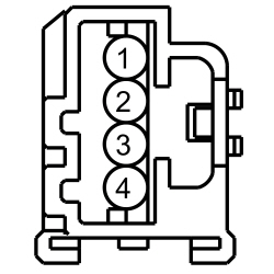 - For power liftgate, connect a
fused jumper wire
between:
| Lead 1
| Lead 2
| | Pin
| Circuit
| Pin
| Circuit
| | C4174B-15
| CPL44 (YE/OG)
| —
| Ground
|
 - Using a scan tool, view
PIDs.
- Monitor the suspect
ajar switch PIDs (DOOR_SW_LUGG, DOOR_SW_DRVR, DOOR_SW_PSGR, DOOR_SW_LR or DOOR_SW_RR).
- Does the PID indicate the door is closed?
| Yes
For LH and RH doors, REMOVE the jumper wire. INSTALL a new door latch or door ajar switch in question. REFER to
Section 501-14A
(without
) or
Section 501-14B
(with
).
For manual liftgate, REMOVE the jumper wire. INSTALL a new liftgate latch. REFER to
Section 501-03
.
For power liftgate, REMOVE the jumper wire. GO to
E6
.
No
For LH and RH doors and manual liftgate, REMOVE the jumper wire. GO to
E3
.
For power liftgate, REMOVE the jumper wire. GO to
E4
.
|
|
E3 BYPASS THE AJAR SWITCH GROUND CIRCUIT
|
|
- For LH or RH doors, connect a
fused jumper wire
between:
| Lead 1
| Lead 2
| | Pin
| Circuit
| Pin
| Circuit
| | LH Front Door Ajar Switch
| | C525-5
| CPL26 (GN/VT)
| —
| Ground
| | RH Front Door Ajar Switch
| | C603-5
| CPL31 (WH)
| —
| Ground
| | LH Rear Door Ajar Switch
| | C704-5
| CPL39 (YE)
| —
| Ground
| | RH Rear Door Ajar Switch
| | C804-5
| CPL39 (YE)
| —
| Ground
|
 - For manual liftgate, connect a
fused jumper wire
between:
| Lead 1
| Lead 2
| | Pin
| Circuit
| Pin
| Circuit
| | C4185-4
| CPL44 (YE/OG)
| —
| Ground
|
 - Using a scan tool, view
PIDs.
- Monitor the suspect
ajar switch PIDs (DOOR_SW_LUGG, DOOR_SW_DRVR, DOOR_SW_PSGR, DOOR_SW_LR or DOOR_SW_RR).
- Does the PID indicate the door is closed?
| Yes
REMOVE the jumper wire. REPAIR the circuit.
No
REMOVE the jumper wire. GO to
E4
.
|
|
E4 CHECK THE AJAR SWITCH INPUT CIRCUIT FOR AN OPEN
|
|
- Ignition OFF.
- Disconnect:
C2280C.
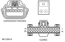
- For LH or RH doors, measure the
resistance
between:
| Positive Lead
| Negative Lead
| | Pin
| Circuit
| Pin
| Circuit
| | LH Front Door Ajar Switch
| | C525-5
| CPL26 (GN/VT)
| C2280C-9
| CPL26 (GN/VT)
| | RH Front Door Ajar Switch
| | C603-5
| CPL31 (WH)
| C2280C-5
| CPL31 (WH)
| | LH Rear Door Ajar Switch
| | C704-5
| CPL39 (YE)
| C2280C-20
| CPL36 (GN)
| | RH Rear Door Ajar Switch
| | C804-5
| CPL39 (YE)
| C2280C-21
| CPL39 (YE)
|
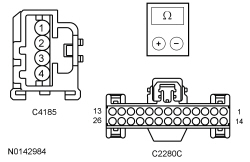
 - For manual liftgate, measure the
resistance
between:
| Lead 1
| Lead 2
| | Pin
| Circuit
| Pin
| Circuit
| | C4185-4
| CPL44 (YE/OG)
| C2280C-19
| CPL44 (YE/OG)
|
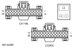
 - For power liftgate, measure the
resistance
between:
| Lead 1
| Lead 2
| | Pin
| Circuit
| Pin
| Circuit
| | C4174B-15
| CPL44 (YE/OG)
| C2280C-19
| CPL44 (YE/OG)
|
 - Is the resistance less than 3 ohms?
| Yes
GO to
E5
.
No
REPAIR the circuit.
|
|
E5 CHECK FOR CORRECT
OPERATION
|
|
- Disconnect and inspect all the
connectors.
- Repair:
- corrosion (install new connector or terminals – clean module pins)
- damaged or bent pins – install new terminals/pins
- pushed-out pins – install new pins as necessary
- Reconnect the
connectors. Make sure they seat and latch correctly.
- Operate the system and determine if the concern is still present.
- Is the concern still present?
| Yes
CHECK On-Line Automotive Service Information System (OASIS) for any applicable TSBs. If a TSB exists for this concern, DISCONTINUE this test and FOLLOW TSB instructions. If no TSBs address this concern, INSTALL a new
. REFER to
Section 419-10
.
No
The system is operating correctly at this time. The concern may have been caused by module connections. ADDRESS the root cause of any connector or pin issues.
|
|
E6 CHECK FOR CORRECT
OPERATION
|
|
- Disconnect and inspect all the
connectors.
- Repair:
- corrosion (install new connector or terminals – clean module pins)
- damaged or bent pins – install new terminals/pins
- pushed-out pins – install new pins as necessary
- Reconnect the
connectors. Make sure they seat and latch correctly.
- Operate the system and determine if the concern is still present.
- Is the concern still present?
| Yes
CHECK On-Line Automotive Service Information System (OASIS) for any applicable TSBs. If a TSB exists for this concern, DISCONTINUE this test and FOLLOW TSB instructions. If no TSBs address this concern, INSTALL a new
. REFER to
Section 501-03
.
No
The system is operating correctly at this time. The concern may have been caused by module connections. ADDRESS the root cause of any connector or pin issues.
|
Pinpoint Test F: The Puddle Lamps Stay On Continuously
Diagnostic Overview
Diagnostics in this manual assume a certain skill level and knowledge of Ford-specific diagnostic practices. Refer to Diagnostic Methods in
Section 100-00
for information about these practices.
Refer to Wiring Diagrams Cell
89
, Interior Lamps for schematic and connector information.
Normal Operation and Fault Conditions
Refer to Courtesy Lamps in
Interior Lighting
.
DTC Fault Trigger Conditions
| DTC
| Description
| Fault Trigger Conditions
|
|---|
| B12C2:15
| Puddle Lamp: Circuit Short To Battery or Open
| Sets when the
detects an open or a short to voltage from the puddle lamp output circuit.
|
Possible Sources
- Wiring, terminals or connectors
PINPOINT TEST F: THE PUDDLE LAMPS STAY ON CONTINUOUSLY
| Test Step
| Result / Action to Take
|
|---|
|
F1 CHECK THE INTERIOR COURTESY LAMPS
|
|
- Ignition OFF.
- Wait 1 minute.
- Are the interior courtesy lamps illuminated?
| Yes
GO to Pinpoint Test E
.
No
GO to
F2
.
|
|
F2 CHECK THE
PUDDLE LAMP OUTPUT CIRCUIT FOR A SHORT TO VOLTAGE
|
|
- Disconnect:
C2280C.
- Ignition ON.
- Do the puddle lamps continue to illuminate?
| Yes
REPAIR circuit CLN25 (VT).
No
GO to
F3
.
|
|
F3 CHECK FOR CORRECT
OPERATION
|
|
- Disconnect and inspect all the
connectors.
- Repair:
- corrosion (install new connector or terminals – clean module pins)
- damaged or bent pins – install new terminals/pins
- pushed-out pins – install new pins as necessary
- Reconnect the
connectors. Make sure they seat and latch correctly.
- Operate the system and determine if the concern is still present.
- Is the concern still present?
| Yes
CHECK On-Line Automotive Service Information System (OASIS) for any applicable TSBs. If a TSB exists for this concern, DISCONTINUE this test and FOLLOW TSB instructions. If no TSBs address this concern, INSTALL a new
. REFER to
Section 419-10
.
No
The system is operating correctly at this time. The concern may have been caused by module connections. ADDRESS the root cause of any connector or pin issues.
|
Pinpoint Test G: The Interior Courtesy Lamps Stay On Continuously
Diagnostic Overview
Diagnostics in this manual assume a certain skill level and knowledge of Ford-specific diagnostic practices. Refer to Diagnostic Methods in
Section 100-00
for information about these practices.
Refer to Wiring Diagrams Cell
89
, Interior Lamps for schematic and connector information.
Normal Operation and Fault Conditions
Refer to Courtesy Lamps in
Interior Lighting
.
DTC Fault Trigger Conditions
| DTC
| Description
| Fault Trigger Conditions
|
|---|
| B1313:15
| Interior Lighting Output: Circuit Short To Battery or Open
| Sets when the
detects an open or a short to voltage from the puddle lamp output circuit.
|
Possible Sources
- Wiring, terminals or connectors
PINPOINT TEST G: THE INTERIOR COURTESY LAMPS STAY ON CONTINUOUSLY
| Test Step
| Result / Action to Take
|
|---|
|
G1 CHECK THE DOOR AJAR SWITCH PIDs
|
|
- Ignition ON.
- Using a scan tool, view
PIDs.
- Monitor the suspect
door ajar switch PIDs (DOOR_SW_DRVR, DOOR_SW_PSGR, DOOR_SW_LR or DOOR_SW_RR) while opening and closing all the doors.
- Do all the door ajar switch PID values agree with the door positions?
| Yes
GO to
G2
.
No
GO to Pinpoint Test E
.
|
|
G2 CHECK THE
INTERIOR COURTESY LAMP OUTPUT CIRCUIT FOR A SHORT TO VOLTAGE
|
|
- Ignition OFF.
- Disconnect:
C2280A.
- Ignition ON.
- Observe the courtesy lamps.
- Do the interior courtesy lamps continue to illuminate?
| Yes
REPAIR circuit VLN33 (GY/VT).
No
GO to
G3
.
|
|
G3 CHECK FOR CORRECT
OPERATION
|
|
- Disconnect and inspect all the
connectors.
- Repair:
- corrosion (install new connector or terminals – clean module pins)
- damaged or bent pins – install new terminals/pins
- pushed-out pins – install new pins as necessary
- Reconnect the
connectors. Make sure they seat and latch correctly.
- Operate the system and determine if the concern is still present.
- Is the concern still present?
| Yes
CHECK On-Line Automotive Service Information System (OASIS) for any applicable TSBs. If a TSB exists for this concern, DISCONTINUE this test and FOLLOW TSB instructions. If no TSBs address this concern, INSTALL a new
. REFER to
Section 419-10
.
No
The system is operating correctly at this time. The concern may have been caused by module connections. ADDRESS the root cause of any connector or pin issues.
|
Pinpoint Test H: All The Demand Lamps Are Inoperative
Diagnostic Overview
Diagnostics in this manual assume a certain skill level and knowledge of Ford-specific diagnostic practices. Refer to Diagnostic Methods in
Section 100-00
for information about these practices.
Refer to Wiring Diagrams Cell
89
, Interior Lamps for schematic and connector information.
Normal Operation and Fault Conditions
Refer to Demand Lamps in
Interior Lighting
.
Possible Sources
- fuse 4 (10A)
- Wiring, terminals or connectors
PINPOINT TEST H: ALL THE DEMAND LAMPS ARE INOPERATIVE
NOTE:
Make sure the battery saver is operating correctly by checking the courtesy lamps first.
| Test Step
| Result / Action to Take
|
|---|
|
H1 BYPASS THE
|
|
- Ignition OFF.
- Disconnect:
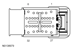
C2280D.
- Connect a
fused jumper wire
between:
| Lead 1
| Lead 2
| | Pin
| Circuit
| Pin
| Circuit
| | C2280D-22
| CLN09 (YE/GN)
| —
| Battery positive
|
 - Do the demand lamps illuminate when switched on?
| Yes
REMOVE the jumper wire. VERIFY the
fuse 4 (10A) is OK. If OK, GO to
H2
. If not OK, REFER to the Wiring Diagrams manual to identify the possible causes of the circuit short.
No
REMOVE the jumper wire. REPAIR the circuit.
|
|
H2 CHECK FOR CORRECT
OPERATION
|
|
- Disconnect and inspect all the
connectors.
- Repair:
- corrosion (install new connector or terminals – clean module pins)
- damaged or bent pins – install new terminals/pins
- pushed-out pins – install new pins as necessary
- Reconnect the
connectors. Make sure they seat and latch correctly.
- Operate the system and determine if the concern is still present.
- Is the concern still present?
| Yes
CHECK On-Line Automotive Service Information System (OASIS) for any applicable TSBs. If a TSB exists for this concern, DISCONTINUE this test and FOLLOW TSB instructions. If no TSBs address this concern, INSTALL a new
. REFER to
Section 419-10
.
No
The system is operating correctly at this time. The concern may have been caused by module connections. ADDRESS the root cause of any connector or pin issues.
|
Pinpoint Test I: An Individual Demand Lamp Is Inoperative
Diagnostic Overview
Diagnostics in this manual assume a certain skill level and knowledge of Ford-specific diagnostic practices. Refer to Diagnostic Methods in
Section 100-00
for information about these practices.
Refer to Wiring Diagrams Cell
89
, Interior Lamps for schematic and connector information.
Normal Operation and Fault Conditions
Refer to Demand Lamps in
Interior Lighting
.
Possible Sources
- Wiring, terminals or connectors
- Demand lamp
PINPOINT TEST I: AN INDIVIDUAL DEMAND LAMP IS INOPERATIVE
| Test Step
| Result / Action to Take
|
|---|
|
I1 CHECK FOR VOLTAGE TO THE DEMAND LAMP
|
|
- Ignition OFF.
- Disconnect: Inoperative Demand Lamp.
- Ignition ON.
- Measure the
voltage
between:
| Positive Lead
| Negative Lead
| | Pin
| Circuit
| Pin
| Circuit
| | LH Vanity Mirror Lamp
| | C907-1
| CLN09 (YE/GN)
| —
| Ground
| | RH Vanity Mirror Lamp
| | C906-1
| CLN09 (YE/GN)
| —
| Ground
| | Front Interior Lamp
| | C929-3
| CLN09 (YE/GN)
| —
| Ground
| | Second Row Lamp (without roof opening panel)
| | C961-3
| CLN09 (YE/GN)
| —
| Ground
| | LH Second Row Lamp (with roof opening panel)
| | C9009-3
| CLN09 (YE/GN)
| —
| Ground
| | RH Second Row Lamp (with roof opening panel)
| | C9010-3
| CLN09 (YE/GN)
| —
| Ground
| | Third Row Lamp
| | C932-3
| CLN09 (YE/GN)
| —
| Ground
|
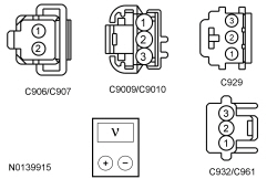 - Is the voltage greater than 11 volts?
| Yes
For inoperative glove compartment lamp only, INSPECT the lamp ground for a loose or corroded connection. If OK, INSTALL a new glove compartment lamp.
For all other demand lamps, GO to
I2
.
No
REPAIR the circuit.
|
|
I2 CHECK THE DEMAND LAMP GROUND CIRCUIT FOR AN OPEN
|
|
- Measure the
voltage
between:
| Positive Lead
| Negative Lead
| | Pin
| Circuit
| Pin
| Circuit
| | LH Vanity Mirror Lamp
| | C907-1
| CLN09 (YE/GN)
| C907-2
| GD233 (BK)
| | RH Vanity Mirror Lamp
| | C906-1
| CLN09 (YE/GN)
| C906-2
| GD233 (BK)
| | Front Interior Lamp
| | C929-3
| CLN09 (YE/GN)
| C929-1
| GD233 (BK)
| | Second Row Lamp (without roof opening panel)
| | C961-3
| CLN09 (YE/GN)
| C961-2
| GD233 (BK)
| | LH Second Row Lamp (with roof opening panel)
| | C9009-3
| CLN09 (YE/GN)
| C9009-2
| GD233 (BK)
| | RH Second Row Lamp (with roof opening panel)
| | C9010-3
| CLN09 (YE/GN)
| C9010-2
| GD233 (BK)
| | Third Row Lamp
| | C932-3
| CLN09 (YE/GN)
| C932-2
| GD233 (BK)
|
 - Is the voltage greater than 11 volts?
| Yes
INSTALL a new demand lamp for the inoperative lamp in question.
No
REPAIR the circuit.
|
Pinpoint Test J: The Battery Saver Does Not Deactivate After Time-Out
Diagnostic Overview
Diagnostics in this manual assume a certain skill level and knowledge of Ford-specific diagnostic practices. Refer to Diagnostic Methods in
Section 100-00
for information about these practices.
Refer to Wiring Diagrams Cell
89
, Interior Lamps for schematic and connector information.
Normal Operation and Fault Conditions
Refer to Battery Saver in
Interior Lighting
.
Possible Sources
- Wiring, terminals or connectors
PINPOINT TEST J: THE BATTERY SAVER DOES NOT DEACTIVATE AFTER TIME-OUT
| Test Step
| Result / Action to Take
|
|---|
|
J1 CHECK THE
IGNITION SWITCH STATE PID
|
|
- Ignition ON.
- Using a scan tool, view
PIDs.
- Monitor the
Ignition Switch PID (IGN_SW_STATE) while changing ignition to OFF.
- Does the ignition PID agree with the ignition state?
| Yes
GO to
J2
.
No
REFER to
Section 211-05
.
|
|
J2 CHECK THE DEMAND LAMP VOLTAGE SUPPLY CIRCUIT FOR A SHORT TO VOLTAGE
|
|
- Ignition OFF.
- Disconnect:
C2280D.
- Ignition ON.
- Operate the demand lamps.
- Do the demand lamps illuminate?
| Yes
REPAIR circuit CLN09 (YE/GN).
No
GO to
J3
.
|
|
J3 CHECK FOR CORRECT
OPERATION
|
|
- Disconnect and inspect all the
connectors.
- Repair:
- corrosion (install new connector or terminals – clean module pins)
- damaged or bent pins – install new terminals/pins
- pushed-out pins – install new pins as necessary
- Reconnect the
connectors. Make sure they seat and latch correctly.
- Operate the system and determine if the concern is still present.
- Is the concern still present?
| Yes
CHECK On-Line Automotive Service Information System (OASIS) for any applicable TSBs. If a TSB exists for this concern, DISCONTINUE this test and FOLLOW TSB instructions. If no TSBs address this concern, INSTALL a new
. REFER to
Section 419-10
.
No
The system is operating correctly at this time. The concern may have been caused by module connections. ADDRESS the root cause of any connector or pin issues.
|
Pinpoint Test K: One Or More Of The Ambient Lighting
Are Inoperative
Diagnostic Overview
Diagnostics in this manual assume a certain skill level and knowledge of Ford-specific diagnostic practices. Refer to Diagnostic Methods in
Section 100-00
for information about these practices.
Refer to Wiring Diagrams Cell
89
, Interior Lamps for schematic and connector information.
Normal Operation and Fault Conditions
Refer to Ambient Lighting in
Interior Lighting
.
Possible Sources
- Wiring, terminals or connectors
- Ambient lighting
harness
- HVAC module
PINPOINT TEST K: ONE OR MORE OF THE AMBIENT LIGHTING
ARE INOPERATIVE
| Test Step
| Result / Action to Take
|
|---|
|
K1 CHECK AMBIENT LIGHTING OPERATION
|
|
- Ignition ON.
- Place the headlamp switch in the parking lamps ON position.
- Observe each of the ambient lamps.
- Are all the ambient lamps inoperative?
| Yes
GO to
K2
.
No
GO to
K7
.
|
|
K2 CHECK FOR COMMUNICATION TO THE HVAC MODULE
|
|
- Ignition ON.
- Using a scan tool, carry out the network test.
- Does the HVAC module pass the network test?
| Yes
GO to
K3
.
No
REFER to
Section 418-00
, The HVAC Module Does Not Respond To The Scan Tool.
|
|
K3 CHECK THE CLIMATE CONTROL OPERATION
|
|
- Check the operation of the climate control system and verify that all of the climate controls operate correctly.
- Does the climate control system operate correctly?
| Yes
GO to
K4
.
No
REFER to
Section 412-00
.
|
|
K4 CHECK THE AMBIENT LIGHTING GROUND CIRCUIT FOR AN OPEN
|
|
- Ignition OFF.
- Disconnect: HVAC Module C228C.
- Disconnect: Negative Battery Cable.
- Measure the
resistance
between:
| Positive Lead
| Negative Lead
| | Pin
| Circuit
| Pin
| Circuit
| | C228C-8
| GD375 (BK/BU)
| —
| Ground
|
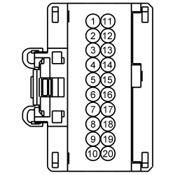 - Is the resistance less than 3 ohms?
| Yes
GO to
K5
.
No
REPAIR the circuit.
|
|
K5 CHECK THE AMBIENT LIGHTING
RETURN CIRCUIT FOR A SHORT TO VOLTAGE
|
|
- Connect: Negative Battery Cable.
- Ignition ON.
- Measure the
voltage
between:
| Positive Lead
| Negative Lead
| | Pin
| Circuit
| Pin
| Circuit
| | C228C-17
| RLN44 (BN)
| —
| Ground
|
 - Is any voltage present?
| Yes
REPAIR the circuit.
No
GO to
K6
.
|
|
K6 CHECK THE AMBIENT LIGHTING
RETURN CIRCUIT FOR AN OPEN
|
|
- Ignition OFF.
- Diode check between:
| Positive Lead
| Negative Lead
| | Pin
| Circuit
| Pin
| Circuit
| | C228C-5
| VLN50 (YE/BU)
| C228C-17
| RLN44 (BN)
|
 - Does the meter indicate the circuit is good?
| Yes
GO to
K8
.
No
REPAIR the affected circuit.
|
|
K7 CHECK THE AMBIENT LIGHTING
RETURN CIRCUIT FOR AN OPEN TO THE
|
|
- Ignition OFF.
- Disconnect: HVAC Module C228C.
- Disconnect: Inoperative Ambient Lighting
Harness Inline Connector.
- Measure the
resistance
between:
| Positive Lead
| Negative Lead
| | Pin
| Circuit
| Pin
| Circuit
| | LH Front Footwell Ambient Lighting
| | C228C-17
| RLN44 (BN)
| C327F-2
| RLN44 (BN)
| | RH Front Footwell Ambient Lighting
| | C228C-17
| RLN44 (BN)
| C3047M-2
| RLN44 (BN)
| | Cupholder Ambient Lighting
| | C228C-17
| RLN44 (BN)
| C313F-2
| RLN44 (BN)
| | Storage Bin, LH and RH Rear Footwell Ambient Lighting
| | C228C-17
| RLN44 (BN)
| C3249M-4
| RLN44 (BN)
|
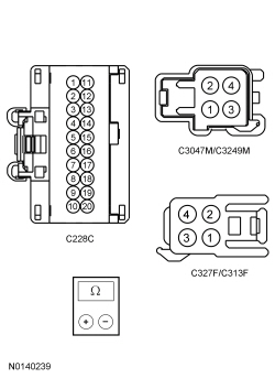 - Is the resistance less than 3 ohms?
| Yes
INSTALL a new ambient lighting harness in question.
No
REPAIR the circuit.
|
|
K8 CHECK FOR CORRECT HVAC MODULE OPERATION
|
|
- Disconnect and inspect all the HVAC module connectors.
- Repair:
- corrosion (install new connector or terminals – clean module pins)
- damaged or bent pins – install new terminals/pins
- pushed-out pins – install new pins as necessary
- Reconnect the HVAC module connectors. Make sure they seat and latch correctly.
- Operate the system and determine if the concern is still present.
- Is the concern still present?
| Yes
CHECK On-Line Automotive Service Information System (OASIS) for any applicable TSBs. If a TSB exists for this concern, DISCONTINUE this test and FOLLOW TSB instructions. If no TSBs address this concern, INSTALL a new HVAC module. REFER to
Section 412-01
.
No
The system is operating correctly at this time. The concern may have been caused by module connections. ADDRESS the root cause of any connector or pin issues.
|
Pinpoint Test L: One Or More Of The Ambient Lighting
Do Not Cycle Through All Color Combinations
Diagnostic Overview
Diagnostics in this manual assume a certain skill level and knowledge of Ford-specific diagnostic practices. Refer to Diagnostic Methods in
Section 100-00
for information about these practices.
Refer to Wiring Diagrams Cell
89
, Interior Lamps for schematic and connector information.
Normal Operation and Fault Conditions
Refer to Ambient Lighting in
Interior Lighting
.
DTC Fault Trigger Conditions
| DTC
| Description
| Fault Trigger Conditions
|
|---|
| B127C:11
| Ambient Lighting Zone 2 Output Red
: Circuit Short To Ground
| Sets when the HVAC module detects a short to ground from a red ambient lighting output circuit.
|
| B127C:12
| Ambient Lighting Zone 2 Output Red
: Circuit Short To Battery
| Sets when the HVAC module detects a short to voltage from a red ambient lighting output circuit.
|
| B127C:13
| Ambient Lighting Zone 2 Output Red
: Circuit Open
| Sets when the HVAC module detects an open from a red ambient lighting output circuit.
|
| B127F:11
| Ambient Lighting Zone 2 Output Green
: Circuit Short To Ground
| Sets when the HVAC module detects a short to ground from a green ambient lighting output circuit.
|
| B127F:12
| Ambient Lighting Zone 2 Output Green
: Circuit Short To Battery
| Sets when the HVAC module detects a short to voltage from a green ambient lighting output circuit.
|
| B127F:13
| Ambient Lighting Zone 2 Output Green
: Circuit Open
| Sets when the HVAC module detects an open from a green ambient lighting output circuit.
|
| B1282:11
| Ambient Lighting Zone 2 Output Blue
: Circuit Short To Ground
| Sets when the HVAC module detects a short to ground from a blue ambient lighting output circuit.
|
| B1282:12
| Ambient Lighting Zone 2 Output Blue
: Circuit Short To Battery
| Sets when the HVAC module detects a short to voltage from a blue ambient lighting output circuit.
|
| B1282:13
| Ambient Lighting Zone 2 Output Blue
: Circuit Open
| Sets when the HVAC module detects an open from a blue ambient lighting output circuit.
|
Possible Sources
- Wiring, terminals or connectors
- HVAC module
- Ambient lighting
harness
PINPOINT TEST L: ONE OR MORE OF THE AMBIENT LIGHTING
DO NOT CYCLE THROUGH ALL COLOR COMBINATIONS
| Test Step
| Result / Action to Take
|
|---|
|
L1 CHECK AMBIENT LIGHTING OPERATION
|
|
- Ignition ON.
- Place the headlamp switch in the parking lamps ON position.
- Observe each of the ambient lamps while changing all the colors.
- Do all the ambient lamps display the same colors?
| Yes
GO to
L2
.
No
GO to
L5
.
|
|
L2 CHECK THE AMBIENT LIGHTING BLUE, GREEN AND RED OUTPUT CIRCUITS FOR A SHORT TO VOLTAGE
|
|
- Ignition OFF.
- Disconnect: HVAC Module C228C.
- Ignition ON.
- Measure the
voltage
between:
| Positive Lead
| Negative Lead
| | Pin
| Circuit
| Pin
| Circuit
| | C228C-5
| VLN50 (YE/BU)
| —
| Ground
| | C228C-6
| VLN49 (YE/GN)
| —
| Ground
| | C228C-7
| VLN48 (YE/OG)
| —
| Ground
|
 - Is any voltage present?
| Yes
REPAIR the affected circuit(s).
No
GO to
L3
.
|
|
L3 CHECK THE AMBIENT LIGHTING BLUE, GREEN AND RED OUTPUT CIRCUITS FOR A SHORT TO GROUND
|
|
- Ignition OFF.
- Measure the
resistance
between:
| Positive Lead
| Negative Lead
| | Pin
| Circuit
| Pin
| Circuit
| | C228C-5
| VLN50 (YE/BU)
| —
| Ground
| | C228C-6
| VLN49 (YE/GN)
| —
| Ground
| | C228C-7
| VLN48 (YE/OG)
| —
| Ground
|
 - Are the resistances greater than 10,000 ohms?
| Yes
GO to
L4
.
No
REPAIR the affected circuit(s).
|
|
L4 CHECK THE AMBIENT LIGHTING BLUE, GREEN AND RED OUTPUT CIRCUITS
|
|
- Diode check between:
| Positive Lead
| Negative Lead
| | Pin
| Circuit
| Pin
| Circuit
| | C228C-5
| VLN50 (YE/BU)
| C228C-17
| RLN44 (BN)
| | C228C-6
| VLN49 (YE/GN)
| C228C-17
| RLN44 (BN)
| | C228C-7
| VLN48 (YE/OG)
| C228C-17
| RLN44 (BN)
|
 - Does the meter indicate the circuits are good?
| Yes
GO to
L6
.
No
REPAIR the affected circuit(s).
|
|
L5 CHECK THE AMBIENT LIGHTING
RETURN CIRCUIT FOR AN OPEN TO THE
|
|
- Disconnect: Inoperative Ambient Lighting
Harness Inline Connector.
- Measure the
resistance
between:
| Positive Lead
| Negative Lead
| | Pin
| Circuit
| Pin
| Circuit
| | LH Front Footwell Ambient Lighting
| | C228C-5
| VLN50 (YE/BU)
| C327F-3
| VLN50 (YE/BU)
| | C228C-6
| VLN49 (YE/GN)
| C327F-4
| VLN49 (YE/GN)
| | C228C-7
| VLN48 (YE/OG)
| C327F-1
| VLN48 (YE/OG)
| | RH Front Footwell Ambient Lighting
| | C228C-5
| VLN50 (YE/BU)
| C3047M-3
| VLN50 (YE/BU)
| | C228C-6
| VLN49 (YE/GN)
| C3047M-4
| VLN49 (YE/GN)
| | C228C-7
| VLN48 (YE/OG)
| C3047M-1
| VLN48 (YE/OG)
| | Cupholder Ambient Lighting
| | C228C-5
| VLN50 (YE/BU)
| C313F-3
| VLN50 (YE/BU)
| | C228C-6
| VLN49 (YE/GN)
| C313F-4
| VLN49 (YE/GN)
| | C228C-7
| VLN48 (YE/OG)
| C313F-1
| VLN48 (YE/OG)
| | Storage Bin, LH and RH Rear Footwell Ambient Lighting
| | C228C-5
| VLN50 (YE/BU)
| C3249M-2
| VLN50 (YE/BU)
| | C228C-6
| VLN49 (YE/GN)
| C3249M-3
| VLN49 (YE/GN)
| | C228C-7
| VLN48 (YE/OG)
| C3249M-1
| VLN48 (YE/OG)
|
 - Are the resistances less than 3 ohms?
| Yes
INSTALL a new ambient lighting harness in question.
No
REPAIR the affected circuit(s).
|
|
L6 CHECK FOR CORRECT HVAC MODULE OPERATION
|
|
- Disconnect and inspect all the HVAC module connectors.
- Repair:
- corrosion (install new connector or terminals – clean module pins)
- damaged or bent pins – install new terminals/pins
- pushed-out pins – install new pins as necessary
- Reconnect the HVAC module connectors. Make sure they seat and latch correctly.
- Operate the system and determine if the concern is still present.
- Is the concern still present?
| Yes
CHECK On-Line Automotive Service Information System (OASIS) for any applicable TSBs. If a TSB exists for this concern, DISCONTINUE this test and FOLLOW TSB instructions. If no TSBs address this concern, INSTALL a new HVAC module. REFER to
Section 412-01
.
No
The system is operating correctly at this time. The concern may have been caused by module connections. ADDRESS the root cause of any connector or pin issues.
|
Pinpoint Test M: The Courtesy Lamps Do Not Illuminate With The Liftgate Open
Diagnostic Overview
Diagnostics in this manual assume a certain skill level and knowledge of Ford-specific diagnostic practices. Refer to Diagnostic Methods in
Section 100-00
for information about these practices.
Refer to Wiring Diagrams Cell
89
, Interior Lamps for schematic and connector information.
Normal Operation and Fault Conditions
Refer to Courtesy Lamps in
Interior Lighting
.
DTC Fault Trigger Conditions
| DTC
| Description
| Fault Trigger Conditions
|
|---|
| B2721
| Liftgate/Decklid Ajar Output Short to Ground or Open
| Sets when the
detects a short to ground from the
liftgate ajar input circuit.
|
Possible Sources
- Wiring, terminals or connectors
- Liftgate latch
PINPOINT TEST M: THE COURTESY LAMPS DO NOT ILLUMINATE WITH THE LIFTGATE OPEN
NOTE:
Make sure that the dark car feature is not enabled in the
. The dark car feature disables activation of courtesy lamps due to a door unlock, door ajar or removing the key from the ignition cylinder. The feature can be disabled using a scan tool.
| Test Step
| Result / Action to Take
|
|---|
|
M1 CHECK THE COURTESY LAMP OPERATION FROM ANY DOOR
|
|
- Ignition OFF.
- Open any door and observe the courtesy lamps.
- Do the courtesy lamps illuminate?
| Yes
GO to
M2
.
No
GO to Pinpoint Test A
.
|
|
M2 CHECK THE
OR THE LIFTGATE LATCH
|
|
- Disconnect: Liftgate Latch C4185 (manual liftgate).
- Disconnect:
C4174B (power liftgate).
- Do the courtesy lamps illuminate?
| Yes
GO to
M4
.
No
GO to
M3
.
|
|
M3 CHECK THE LIFTGATE AJAR INPUT CIRCUIT FOR A SHORT TO GROUND
|
|
- Disconnect:
C2280C.
- Measure the
resistance
between:
| Positive Lead
| Negative Lead
| | Pin
| Circuit
| Pin
| Circuit
| | C2280C-19
| CPL44 (YE/OG)
| —
| Ground
|
 - Is the resistance greater than 10,000 ohms?
| Yes
GO to
M5
.
No
REPAIR the circuit.
|
|
M4 CHECK FOR CORRECT
OPERATION
|
|
- Disconnect and inspect all the
connectors.
- Repair:
- corrosion (install new connector or terminals – clean module pins)
- damaged or bent pins – install new terminals/pins
- pushed-out pins – install new pins as necessary
- Reconnect the
connectors. Make sure they seat and latch correctly.
- Operate the system and determine if the concern is still present.
- Is the concern still present?
| Yes
CHECK On-Line Automotive Service Information System (OASIS) for any applicable TSBs. If a TSB exists for this concern, DISCONTINUE this test and FOLLOW TSB instructions. If no TSBs address this concern, INSTALL a new
. REFER to
Section 501-03
.
No
The system is operating correctly at this time. The concern may have been caused by module connections. ADDRESS the root cause of any connector or pin issues.
|
|
M5 CHECK FOR CORRECT
OPERATION
|
|
- Disconnect and inspect all the
connectors.
- Repair:
- corrosion (install new connector or terminals – clean module pins)
- damaged or bent pins – install new terminals/pins
- pushed-out pins – install new pins as necessary
- Reconnect the
connectors. Make sure they seat and latch correctly.
- Operate the system and determine if the concern is still present.
- Is the concern still present?
| Yes
CHECK On-Line Automotive Service Information System (OASIS) for any applicable TSBs. If a TSB exists for this concern, DISCONTINUE this test and FOLLOW TSB instructions. If no TSBs address this concern, INSTALL a new
. REFER to
Section 419-10
.
No
The system is operating correctly at this time. The concern may have been caused by module connections. ADDRESS the root cause of any connector or pin issues.
|


