SECTION 419-01B: Anti-Theft — Passive Anti-Theft System (PATS), Without Intelligent Access (IA)
| 2014 Flex Workshop Manual
|
DIAGNOSIS AND TESTING
| Procedure revision date: 05/02/2013
|
Anti-Theft
DTC Charts
Diagnostics in this manual assume a certain skill level and knowledge of Ford-specific diagnostic practices. Refer to Diagnostic Methods in
Section 100-00
for information about these practices.
DTC Chart
PCM DTC Chart
Symptom Chart
Diagnostics in this manual assume a certain skill level and knowledge of Ford-specific diagnostic practices. Refer to Diagnostic Methods in
Section 100-00
for information about these practices.
Symptom Chart: Passive Anti-Theft System (PATS)
| Condition
| Possible Sources
| Action
|
|---|
- The engine does not start
| - Refer to the Diagnostic Routine
| |
- STARTING SYSTEM FAULT is displayed in the message center
| | - RETRIEVE and DIAGNOSE all
DTCs in the
. REFER to the Related Module DTC Chart:
.
|
- All keys are lost, the perimeter alarm is active and unable to program new keys
| - Unable to enter security access
| |
Pinpoint Tests
Pinpoint Test A: The Engine Does Not Start
Diagnostic Overview
Diagnostics in this manual assume a certain skill level and knowledge of Ford-specific diagnostic practices. Refer to Diagnostic Methods in
Section 100-00
for information about these practices.
Normal Operation and Fault Conditions
Refer to System Operation - Passive Anti-Theft System (PATS) in
Anti-Theft
.
Refer to Component Description - Integrated Keyhead Transmitter (IKT) in
Anti-Theft
.
Refer to Component Description - Passive Anti-Theft System (PATS) Transceiver in
Anti-Theft
.
Possible Sources:
- Driveability system concern
- Starting system concern
- concern
PINPOINT TEST A: THE ENGINE DOES NOT START
| Test Step
| Result / Action to Take
|
|---|
|
A1 CHECK FOR COMMUNICATION WITH THE PCM AND THE
|
|
- Ignition ON.
- Using a scan tool, perform the network test.
- Does the PCM and the
pass the network test?
| Yes
GO to
A2
.
No
REFER to
Section 418-00
to diagnose the PCM or the
not responding to the scan tool.
|
|
A2 CHECK FOR
DTCs
|
|
- Using a scan tool, perform the
self-test.
- Are any
DTCs present?
| Yes
REFER to the
DTC Chart.
No
The no-start condition is not caused by the
. REFER to the Powertrain Control/Emissions Diagnosis (PC/ED) manual to diagnose the cause of the no-start condition.
|
Pinpoint Test B: B10D7:05
Diagnostic Overview
Diagnostics in this manual assume a certain skill level and knowledge of Ford-specific diagnostic practices. Refer to Diagnostic Methods in
Section 100-00
for information about these practices.
Normal Operation and Fault Conditions
When the
enters a key programming state, it activates the transceiver to read the key in the ignition key cylinder. If a valid
key is used and there are no concerns with the
, the key is programmed into the
memory.
DTC Fault Trigger Conditions
| DTC
| Description
| Fault Trigger Conditions
|
|---|
| PATS Key: System Programming Failure
| Sets when a
key is not successfully programmed into the
.
|
Possible Sources:
- key not programmed
Visual Inspection and Diagnostic Pre-checks
- Inspect the
key for damage.
- Verify the correct key is used.
PINPOINT TEST B: B10D7:05
Pinpoint Test C: B10D7:87 or B10D7:8F
Diagnostic Overview
Diagnostics in this manual assume a certain skill level and knowledge of Ford-specific diagnostic practices. Refer to Diagnostic Methods in
Section 100-00
for information about these practices.
Normal Operation and Fault Conditions
When the ignition transitions to RUN or START, the
activates the transceiver to read the key in the ignition key cylinder. If the
does not receive a
key code or if the code is invalid, the
does not allow the engine does not start.
DTC Fault Trigger Conditions
| DTC
| Description
| Fault Trigger Conditions
|
|---|
| PATS Key: Missing Message
| Sets when the
does not read a
key when the ignition transitions to RUN.
|
| PATS Key: Erratic
| Sets when the
receives a partial or corrupt
key read.
|
Possible Sources:
- key
- transceiver
Visual Inspection and Diagnostic Pre-checks
- Inspect the
key for damage.
- Verify the correct key is used.
PINPOINT TEST C: B10D7:87 OR B10D7:8F
NOTE:
This pinpoint test requires a second programmed
keys. If only one key is available, a second programmed
key must be obtained.
Pinpoint Test D: B10D9:87
Diagnostic Overview
Diagnostics in this manual assume a certain skill level and knowledge of Ford-specific diagnostic practices. Refer to Diagnostic Methods in
Section 100-00
for information about these practices.
Refer to Wiring Diagrams Cell
112
, Passive Anti-Theft System for schematic and connector information.
Normal Operation and Fault Conditions
The
supplies voltage to the
transceiver. When the ignition changes to RUN or START, the
initiates the key interrogation sequence. The
starts the interrogation sequence by generating a signal and sending that signal to the transceiver on the transmit (TX) circuit. When the transceiver receives the signal from the
, it reads the
key and generates a challenge response to the
signal. The transceiver sends the challenge response back to the
on the receive (RX) circuit.
DTC Fault Trigger Conditions
| DTC
| Description
| Fault Trigger Conditions
|
|---|
| PATS Transponder: Missing Message
| Sets when the
does not receive a response from the
transceiver.
|
Possible Sources:
- Fuse
- Wiring, terminals or connectors
- transceiver
Visual Inspection and Diagnostic Pre-checks
- Verify the
fuse 18 (10A) is OK.
PINPOINT TEST D: B10D9:87
NOTICE:
Use the correct probe adapter(s) when making measurements. Failure to use the correct probe adapter(s) may damage the connector.
| Test Step
| Result / Action to Take
|
|---|
|
D1 REVIEW THE
DTCs FROM THE ON-DEMAND SELF-TEST
|
|
- Review the
DTCs from the on-demand self-test.
- Is DTC C113A:11 or DTC C113A:15 present?
| Yes
GO to Pinpoint Test E
.
No
GO to
D2
.
|
|
D2 CHECK THE
TRANSCEIVER VOLTAGE SUPPLY CIRCUIT FOR AN OPEN
|
|
- Ignition OFF.
- Disconnect:
Transceiver C252.
- Ignition ON.
- Measure the voltage between the
transceiver C252-1, circuit CE436 (VT/OG), harness side and ground.
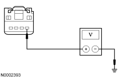 - Is the voltage greater than 11 volts?
| Yes
GO to
D3
.
No
VERIFY the
fuse 18 (10A) is OK. If OK, REPAIR the circuit. If not OK, REFER to the Wiring Diagrams manual to identify the possible causes of the circuit short.
|
|
D3 CHECK THE
TRANSCEIVER GROUND CIRCUIT FOR AN OPEN
|
|
- Measure the voltage between the
transceiver C252-1, circuit CE436 (VT/OG), harness side and the
transceiver C252-2, circuit GD374 (BK/WH).
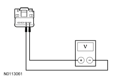 - Is the voltage greater than 11 volts?
| Yes
GO to
D4
.
No
REPAIR the circuit.
|
|
D4 CHECK THE
TRANSCEIVER CIRCUITS FOR A SHORT TO VOLTAGE
|
|
- Ignition OFF.
- Disconnect:
C2280B.
- Ignition ON.
- Measure the voltage between the
transceiver C252-3, circuit VRT24 (YE/OG), harness side and ground; and between the
transceiver C252-4, circuit VRT23 (VT/GY), harness side and ground.
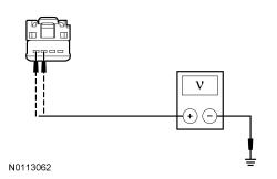 - Is any voltage present?
| Yes
REPAIR the circuit in question.
No
GO to
D5
.
|
|
D5 CHECK THE
TRANSCEIVER CIRCUITS FOR A SHORT TO GROUND
|
|
- Ignition OFF.
- Measure the resistance between the
transceiver C252-3, circuit VRT24 (YE/OG), harness side and ground; and between the
transceiver C252-4, circuit VRT23 (VT/GY), harness side and ground.
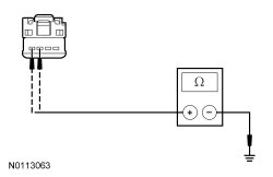 - Are the resistances greater than 10,000 ohms?
| Yes
GO to
D6
.
No
REPAIR the circuit in question.
|
|
D6 CHECK THE
TRANSCEIVER CIRCUITS FOR AN OPEN
|
|
- Measure the resistance between the
, harness side and the
transceiver, harness side as follows:
| Connector-Pin
| Circuit
| Transceiver Connector-Pin
|
|---|
| C2280B-37
| VRT24 (YE/OG)
| C252-3
| | C2280B-36
| VRT23 (VT/GY)
| C252-4
|
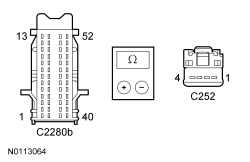 - Are the resistances less than 3 ohms?
| Yes
INSTALL a new
transceiver. REFER to
Passive Anti-Theft System (PATS) Transceiver
. CLEAR the DTCs and REPEAT the
self-test. If DTC B10D9:87 is retrieved again, GO to
D7
.
No
REPAIR the circuit in question.
|
|
D7 CHECK FOR CORRECT
OPERATION
|
|
- Disconnect and inspect all the
connectors.
- Repair:
- corrosion (install new connector or terminals – clean module pins)
- damaged or bent pins – install new terminals/pins
- pushed-out pins – install new pins as necessary
- Reconnect the
connectors. Make sure they seat correctly.
- Operate the system and determine if the concern is still present.
- Is the concern still present?
| Yes
CHECK On-Line Automotive Service Information System (OASIS) for any applicable
. If a
exists for this concern, DISCONTINUE this test and FOLLOW
instructions. If no
address this concern, INSTALL a new
. REFER to
Section 419-10
.
No
The system is operating correctly at this time. The concern may have been caused by module connections. ADDRESS the root cause of any connector or pin issues.
|
Pinpoint Test E: C113A:11 or C113A:15
Diagnostic Overview
Diagnostics in this manual assume a certain skill level and knowledge of Ford-specific diagnostic practices. Refer to Diagnostic Methods in
Section 100-00
for information about these practices.
Refer to Wiring Diagrams Cell
112
, Passive Anti-Theft System for schematic and connector information.
Normal Operation and Fault Conditions
The wakeup control circuit wakes up the PCM prior to engine cranking. The PCM needs to wake up prior to a crank request so that it has time to go through its initialization. The wakeup control circuit also powers the
transceiver. The wakeup control circuit is controlled by the
. The wakeup control circuit is
protected.
The
activates the wakeup control circuit when:
- the driver door is opened,
- a remote start request is received (if equipped with factory remote start),
- the brake pedal is applied,
- a key is inserted into the ignition key cylinder, or
- the ignition is in RUN or START.
DTC Fault Trigger Conditions
| DTC
| Description
| Fault Trigger Conditions
|
|---|
| Wakeup Control: Circuit Short To Ground
| Sets when the
detects a short to ground from the wakeup control output circuit.
|
| Wakeup Control: Circuit Short To Battery or Open
| Sets when the
detects an open or short to voltage from the wakeup control output circuit.
|
Possible Sources:
- Wiring, terminals or connectors
- transceiver
- PCM
Visual Inspection and Diagnostic Pre-checks
- Verify the
fuse 18 (10A) is OK.
PINPOINT TEST E: C113A:11 OR C113A:15
| Test Step
| Result / Action to Take
|
|---|
|
E1 REVIEW THE
DTCs FROM THE SELF-TEST
|
|
- Review the DTCs from the
self-test.
- Is DTC C113A:11 present?
| Yes
GO to
E2
.
No
GO to
E5
.
|
|
E2 ISOLATE THE PCM AS THE CAUSE FOR A SHORT TO GROUND
|
|
- Ignition OFF.
- Disconnect: PCM C175B (3.5L Ti-VCT) or C1381B (2.0L GTDI or 3.5L GTDI).
- Ignition ON.
- Using a scan tool, clear the
DTCs.
- Using a scan tool, perform the
self-test.
- Is DTC C113A:11 still present?
| Yes
GO to
E3
.
No
GO to
E9
.
|
|
E3 ISOLATE THE
TRANSCEIVER AS THE CAUSE FOR A SHORT TO GROUND
|
|
- Ignition OFF.
- Disconnect:
Transceiver C252.
- Ignition ON.
- Using a scan tool, clear the
DTCs.
- Using a scan tool, perform the
self-test.
- Is DTC C113A:11 still present?
| Yes
GO to
E4
.
No
INSTALL a new
transceiver. REFER to
Passive Anti-Theft System (PATS) Transceiver
.
|
|
E4 CHECK THE WAKEUP CONTROL OUTPUT CIRCUIT FOR A SHORT TO GROUND
|
|
- Ignition OFF.
- Disconnect:
C2280F.
- Measure the resistance between the
C2280F-5, circuit CE436 (VT/OG), harness side and ground.
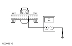 - Is the resistance greater than 10,000 ohms?
| Yes
GO to
E10
.
No
REPAIR the circuit.
|
|
E5 CHECK THE WAKEUP CONTROL CIRCUIT FOR AN OPEN OR SHORT TO VOLTAGE
|
|
- Attempt to start the engine.
- Does the engine start?
| Yes
GO to
E7
.
No
GO to
E6
.
|
|
E6 CHECK THE WAKEUP CONTROL CIRCUIT FOR AN OPEN
|
|
- Ignition OFF.
- Disconnect:
Transceiver C252.
- Disconnect:
C2280F.
- Measure the resistance between the
transceiver C252-1, circuit CE436 (VT/OG), harness side and the
C2280F-5, circuit CE436 (VT/OG), harness side.
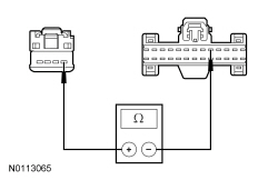 - Is the resistance less than 5 ohms?
| Yes
GO to
E10
.
No
REPAIR the circuit.
|
|
E7 ISOLATE THE
AS THE CAUSE FOR A SHORT TO VOLTAGE
|
|
- Ignition OFF.
- Disconnect:
Transceiver C252.
- Disconnect:
C2280F.
- Ignition ON.
- Measure the voltage between the
transceiver C252-1, circuit CE436 (VT/OG), harness side and ground.
 - Is any voltage present?
| Yes
GO to
E8
.
No
GO to
E10
.
|
|
E8 CHECK THE WAKEUP CONTROL OUTPUT CIRCUIT FOR A SHORT TO VOLTAGE
|
|
- Ignition OFF.
- Disconnect: PCM C175B (3.5L Ti-VCT) or C1381B (2.0L GTDI or 3.5L GTDI).
- Ignition ON.
- Measure the voltage between the
transceiver C252-1, circuit CE436 (VT/OG), harness side and ground.
 - Is any voltage present?
| Yes
REPAIR the circuit.
No
GO to
E9
.
|
|
E9 CHECK FOR CORRECT PCM OPERATION
|
|
- Disconnect and inspect all the PCM connectors.
- Repair:
- corrosion (install new connector or terminals – clean module pins)
- damaged or bent pins – install new terminals/pins
- pushed-out pins – install new pins as necessary
- Reconnect the PCM connectors. Make sure they seat correctly.
- Operate the system and determine if the concern is still present.
- Is the concern still present?
| Yes
CHECK On-Line Automotive Service Information System (OASIS) for any applicable
. If a
exists for this concern, DISCONTINUE this test and FOLLOW
instructions. If no
address this concern, INSTALL a new PCM. REFER to
Section 303-14
.
No
The system is operating correctly at this time. The concern may have been caused by module connections. ADDRESS the root cause of any connector or pin issues.
|
|
E10 CHECK FOR CORRECT
OPERATION
|
|
- Disconnect and inspect all the
connectors.
- Repair:
- corrosion (install new connector or terminals – clean module pins)
- damaged or bent pins – install new terminals/pins
- pushed-out pins – install new pins as necessary
- Reconnect the
connectors. Make sure they seat correctly.
- Operate the system and determine if the concern is still present.
- Is the concern still present?
| Yes
CHECK On-Line Automotive Service Information System (OASIS) for any applicable
. If a
exists for this concern, DISCONTINUE this test and FOLLOW
instructions. If no
address this concern, INSTALL a new
. REFER to
Section 419-10
.
No
The system is operating correctly at this time. The concern may have been caused by module connections. ADDRESS the root cause of any connector or pin issues.
|


