SECTION 419-04: Side And Rear Vision
| 2014 Flex Workshop Manual
|
DIAGNOSIS AND TESTING
| Procedure revision date: 05/02/2013
|
Blind Spot Monitoring
DTC Charts
Diagnostics in this manual assume a certain skill level and knowledge of Ford-specific diagnostic practices. Refer to Diagnostic Methods in
Section 100-00
for information about these practices.
Side Obstacle Detection Control Module - Left (SOD-L) and Side Obstacle Detection Control Module - Right (SOD-R) DTC Chart
| DTC
| Description
| Action
|
|---|
| B11D6:11
| Driver Display Alert LED: Circuit Short To Ground
| GO to Pinpoint Test D
.
|
| B11D6:15
| Driver Display Alert LED: Circuit Short To Battery Or Open
| If the LED is not illuminated,
GO to Pinpoint Test D
.
If the LED is always on,
GO to Pinpoint Test I
.
|
| U0140:00
| Lost Communication With Body Control Module: No Sub Type Information
| GO to Pinpoint Test J
.
|
| U0423:00
| Invalid Data Received From Instrument Panel Cluster Control Module: No Sub Type Information
| DTC U0423:00 is set when the
or
receives invalid network data from the
. RETRIEVE and REPAIR all non-network DTCs in the
. REFER to
Section 413-01
.
|
| U2100:00
| Initial Configuration Not Complete: No Sub Type Information
| The Side Obstacle Detection Control Module - Left (SOD-L) or Side Obstacle Detection Control Module - Right (SOD-R) is not configured. REFER to
Section 418-01
for Programmable Module Installation (PMI) to configure the
or
.
|
| U3000:44
| Control Module: Data Memory Failure
| GO to Pinpoint Test H
.
|
| U3000:45
| Control Module: Program Memory Failure
| GO to Pinpoint Test H
.
|
| U3000:46
| Control Module: Calibration/Parameter Memory Failure
| GO to Pinpoint Test H
.
|
| U3000:48
| Control Module: Supervision Software Failure
| GO to Pinpoint Test H
.
|
| U3000:49
| Control Module: Internal Electronic Failure
| GO to Pinpoint Test H
.
|
| U3000:4A
| Control Module: Incorrect Component Installed
| GO to Pinpoint Test H
.
|
Symptom Chart
Diagnostics in this manual assume a certain skill level and knowledge of Ford-specific diagnostic practices. Refer to Diagnostic Methods in
Section 100-00
for information about these practices.
Symptom Chart
| Condition
| Possible Sources
| Action
|
|---|
- is inoperative/does not operate correctly
| - Refer to the Diagnostic Routine
| |
| - Refer to the Diagnostic Routine
| |
- has no message center warning message and the exterior mirror
/
LED is not illuminated
| - Refer to the Diagnostic Routine
| |
- The
system is inoperative/does not operate correctly or poor performance and no warning LED indicators present
| - Refer to the Diagnostic Routine
| |
- The
system has poor performance
| - Refer to the Diagnostic Routine
| |
- The
system has no message center warning message and the exterior mirror
/
LED is not illuminated
| - Refer to the Diagnostic Routine
| |
- The exterior mirror
/
LED does not illuminate when the tone sounds for the
system
| - Refer to the Diagnostic Routine
| |
- An exterior mirror
/
LED is constantly on
| - Refer to the Diagnostic Routine
| |
- The left or right exterior mirror Blind Spot Information System (BLIS®)/Cross Traffic Alert (CTA) LED appears dim or does not illuminate with no DTC or message in the Instrument Panel Cluster (IPC) message center present
| - Refer to the Diagnostic Routine
| |
- The left or right exterior mirror
/
LED is constantly on and a message in the
message center is present, but no DTCs are recorded
| - Refer to the Diagnostic Routine
| |
- The
or
does not respond to the scan tool
| - Wiring, terminals and connectors
| - REFER to
Section 418-00
, The
Does Not Respond To The Scan Tool or The
Does Not Respond To The Scan Tool.
|
- The
does not respond to the scan tool or cannot be configured
| - Refer to the Diagnostic Routine
| |
- The
message center displays a blocked sensor message
| - Refer to the Diagnostic Routine
| |
- The
or the
system cannot be turned off in the
message center
| - Refer to the Diagnostic Routine
| |
| | - VERIFY if a MyKey® is in use.
|
Pinpoint Tests
Pinpoint Test A:
Is Inoperative Or Does Not Operate Correctly
Diagnostic Overview
Diagnostics in this manual assume a certain skill level and knowledge of Ford-specific diagnostic practices. Refer to Diagnostic Methods in
Section 100-00
for information about these practices.
Normal Operation and Fault Conditions
Refer to
in
Blind Spot Monitoring
.
Possible Sources
- Wiring, terminals and connectors
- Build up or debris on the rear bumper cover sides
- system is not configured on with the scan tool
- Vehicle speed signal (speedometer inoperative)
PINPOINT TEST A:
IS INOPERATIVE OR DOES NOT OPERATE CORRECTLY
NOTICE:
Use the correct probe adapter(s) when making measurements. Failure to use the correct probe adapter(s) may damage the connector.
| Test Step
| Result / Action to Take
|
|---|
|
A1 CHECK THE
/
LED OPERATION
|
|
- Start the engine.
- Observe the left and right exterior mirror
/
LEDs.
- Do the left and right
/
LEDs illuminate and turn off after 3 seconds?
| Yes
GO to
A2
.
No
GO to Pinpoint Test D
.
|
|
A2 VERIFY
OPERATION
|
|
- Drive the vehicle and test
to verify the customers concern.
- Does
operate correctly?
| Yes
The fault may have been caused by an intermittent condition such as poor weather conditions or customers perception of how
operates, REFER to the Owner's Literature.
No
GO to
A3
.
|
|
A3 CHECK FOR
AND
OBSTRUCTIONS
|
|
- Check the lower rear side bumper cover fascia for a build up of mud, bumper stickers or any obstruction.
- Are any obstructions present?
| Yes
CLEAN and REMOVE all obstructions from the lower rear side bumper cover fascia and lower rear bumper cover splash shield.
No
GO to
A4
.
|
|
A4 CHECK FOR DAMAGE TO THE LOWER REAR SIDE BUMPER COVER OR THE
AND
|
|
- Check the lower rear side bumper cover fascia and the
and
mounting bracket for damage.
- Is any damage present?
| Yes
REPAIR or INSTALL any damaged parts.
No
GO to
A5
.
|
|
A5 VERIFY THE
AND
PASS THE NETWORK TEST
|
|
- Using a scan tool, perform the network test.
- Do the
and/or
pass the network test?
| Yes
GO to
A6
.
No
For the
, REFER to
Section 418-00
, The
Does Not Respond To The Scan Tool.
For the
,
GO to Pinpoint Test E
.
|
|
A6 VERIFY
CONFIGURATION
|
|
| Yes
GO to
A7
.
No
ENABLE
in the
and
using the scan tool programmable parameters menu.
|
|
A7 CHECK THE DTCs FROM BOTH THE CONTINUOUS AND ON-DEMAND
AND
SELF-TESTS
|
|
- Using a scan tool, perform the
and
self-tests.
- Are any
and
DTCs recorded?
| Yes
REFER to DTC Charts in this section.
No
For an inoperative
, GO to
A8
.
For an inoperative
, GO to
A9
.
|
|
A8 CHECK FOR CORRECT
OPERATION
|
|
- Disconnect the
connector.
- Repair:
- corrosion (install new connector or terminals - clean module pins)
- damaged pins - install new terminals/pins
- pushed-out pins - install new pins as necessary
- Reconnect the
connector and make sure it seats and latches correctly.
- Operate the system and determine if the concern is still present.
- Is the concern still present?
| Yes
CHECK
for any applicable TSBs. If a TSB exists for this concern, DISCONTINUE this test and FOLLOW TSB instructions. If no TSBs address this concern, INSTALL a new
. REFER to
Side Obstacle Detection (SOD) Module
.
No
The system is operating correctly at this time. The concern may have been caused by module connections. ADDRESS the root cause of any connector or pin issues.
|
|
A9 CHECK FOR CORRECT
OPERATION
|
|
- Disconnect the
connector.
- Repair:
- corrosion (install new connector or terminals - clean module pins)
- damaged pins - install new terminals/pins
- pushed-out pins - install new pins as necessary
- Reconnect the
connector and make sure it seats and latches correctly.
- Operate the system and determine if the concern is still present.
- Is the concern still present?
| Yes
CHECK
for any applicable TSBs. If a TSB exists for this concern, DISCONTINUE this test and FOLLOW TSB instructions. If no TSBs address this concern, INSTALL a new
. REFER to
Side Obstacle Detection (SOD) Module
.
No
The system is operating correctly at this time. The concern may have been caused by module connections. ADDRESS the root cause of any connector or pin issues.
|
Pinpoint Test B: The
System Is Inoperative Or Does Not Operate Correctly
Diagnostic Overview
Diagnostics in this manual assume a certain skill level and knowledge of Ford-specific diagnostic practices. Refer to Diagnostic Methods in
Section 100-00
for information about these practices.
Normal Operation and Fault Conditions
Refer to
System in
Blind Spot Monitoring
.
Refer to Exterior Mirror Indication in
Blind Spot Monitoring
.
Refer to System Diagram in
Blind Spot Monitoring
.
Refer to Network Message Chart in
Blind Spot Monitoring
.
NOTE:
The
system is turned off for one key cycle only when using the message center switches. Permanently disabling the
system is carried out in the Integrated Diagnostic System (IDS) programmable parameters menu.
The
and
are identical modules except that the
uses an address ground pin for configuration. The address ground is necessary so that the
system can decipher between the right and the left module.
Possible Sources
- Wiring, terminals and connectors
- Build up or debris on the rear bumper cover sides
- system is not configured on with the scan tool
- Vehicle speed signal
PINPOINT TEST B: THE
SYSTEM IS INOPERATIVE OR DOES NOT OPERATE CORRECTLY
NOTICE:
Use the correct probe adapter(s) when making measurements. Failure to use the correct probe adapter(s) may damage the connector.
| Test Step
| Result / Action to Take
|
|---|
|
B1 VERIFY THE
/
LED OPERATION
|
|
- Start the engine.
- Observe the left and right exterior mirror
/
LEDs.
- Do the left and right
/
LEDs illuminate and turn off after 3 seconds?
| Yes
GO to
B2
.
No
GO to Pinpoint Test D
.
|
|
B2 VERIFY THE
SYSTEM OPERATION
|
|
- NOTE:
The
system only operates in reverse (R) while backing out of a front-in parking space.
- Test the
system to verify the customers concern.
- Does the
system operate correctly?
| Yes
The fault may have been caused by an intermittent condition such as poor weather conditions or customers perception of how the
system operates. REFER to the Owner's Literature.
No
GO to
B3
.
|
|
B3 CHECK FOR
AND
OBSTRUCTIONS
|
|
- Check the lower rear side bumper cover fascia and lower rear bumper cover splash shield for a build up of mud, bumper stickers or any obstruction.
- Are any obstructions present?
| Yes
CLEAN and REMOVE all obstructions from the lower rear side bumper cover fascia and lower rear bumper cover splash shield.
No
GO to
B4
.
|
|
B4 CHECK FOR DAMAGE TO THE LOWER REAR SIDE BUMPER COVER OR THE
AND
|
|
- Check the lower rear side bumper cover fascia and the
and
mounting bracket for damage.
- Is any damage present?
| Yes
REPAIR or INSTALL any damaged parts.
No
GO to
B5
.
|
|
B5 VERIFY THE
AND
PASS THE NETWORK TEST
|
|
- Using a scan tool, perform the network test.
- Do the
and
pass the network test?
| Yes
GO to
B6
.
No
For the
, REFER to
Section 418-00
, The
Does Not Respond To The Scan Tool.
For the
,
GO to Pinpoint Test E
.
|
|
B6 VERIFY THE
SYSTEM CONFIGURATION
|
|
| Yes
GO to
B7
.
No
ENABLE the
system in the
and
using the scan tool programmable parameters menu.
|
|
B7 CHECK THE DTCs FROM BOTH THE CONTINUOUS AND ON-DEMAND
AND
SELF-TESTS
|
|
- Using a scan tool, perform the
and
self-tests.
- Are any
and
DTCs recorded?
| Yes
REFER to DTC Charts in this section.
No
GO to
B8
.
|
|
B8 CHECK THE DTCs FROM BOTH THE CONTINUOUS AND ON-DEMAND
SELF-TESTS
|
|
- Using a scan tool, perform the
self-test.
- Are any
DTCs recorded?
| Yes
REFER to
Section 413-13A
. REPAIR all
DTCs and TEST the
system for normal operation.
No
For an inoperative
, GO to
B9
.
For an inoperative
, GO to
B10
.
|
|
B9 CHECK FOR CORRECT
OPERATION
|
|
- Disconnect the
connector.
- Repair:
- corrosion (install new connector or terminals - clean module pins)
- damaged pins - install new terminals/pins
- pushed-out pins - install new pins as necessary
- Reconnect the
connector and make sure it seats and latches correctly.
- Operate the system and determine if the concern is still present.
- Is the concern still present?
| Yes
CHECK
for any applicable TSBs. If a TSB exists for this concern, DISCONTINUE this test and FOLLOW TSB instructions. If no TSBs address this concern, INSTALL a new
. REFER to
Side Obstacle Detection (SOD) Module
.
No
The system is operating correctly at this time. The concern may have been caused by module connections. ADDRESS the root cause of any connector or pin issues.
|
|
B10 CHECK FOR CORRECT
OPERATION
|
|
- Disconnect the
connector.
- Repair:
- corrosion (install new connector or terminals - clean module pins)
- damaged pins - install new terminals/pins
- pushed-out pins - install new pins as necessary
- Reconnect the
connector and make sure it seats and latches correctly.
- Operate the system and determine if the concern is still present.
- Is the concern still present?
| Yes
CHECK
for any applicable TSBs. If a TSB exists for this concern, DISCONTINUE this test and FOLLOW TSB instructions. If no TSBs address this concern, INSTALL a new
. REFER to
Side Obstacle Detection (SOD) Module
.
No
The system is operating correctly at this time. The concern may have been caused by module connections. ADDRESS the root cause of any connector or pin issues.
|
Pinpoint Test C: An Exterior Mirror LED Is Constantly On and An
Message Is Present
Diagnostic Overview
Diagnostics in this manual assume a certain skill level and knowledge of Ford-specific diagnostic practices. Refer to Diagnostic Methods in
Section 100-00
for information about these practices.
Normal Operation and Fault Conditions
Refer to Exterior Mirror Indication in
Blind Spot Monitoring
.
Refer to System Diagram in
Blind Spot Monitoring
.
Refer to Network Message Chart in
Blind Spot Monitoring
.
Possible Sources
- Wiring, terminals and connectors
- Speedometer inoperative
PINPOINT TEST C: AN EXTERIOR MIRROR LED IS CONSTANTLY ON AND AN
MESSAGE IS PRESENT
NOTICE:
Use the correct probe adapter(s) when making measurements. Failure to use the correct probe adapter(s) may damage the connector.
| Test Step
| Result / Action to Take
|
|---|
|
C1 VERIFY THE
AND
PASS THE NETWORK TEST
|
|
- Using a scan tool, perform the network test.
- Do the
and
pass the network test?
| Yes
GO to
C2
.
No
For the
, REFER to
Section 418-00
, The
Does Not Respond To The Scan Tool.
For the
,
GO to Pinpoint Test E
.
|
|
C2 CHECK FOR
DTCs
|
|
- Using a scan tool, perform the
self-test.
- Are DTCs present?
| Yes
REFER to
Section 413-13A
.
No
GO to Pinpoint Test B
.
|
Pinpoint Test D: DTC B11D6:11 Or DTC B11D6:15
Diagnostic Overview
Diagnostics in this manual assume a certain skill level and knowledge of Ford-specific diagnostic practices. Refer to Diagnostic Methods in
Section 100-00
for information about these practices.
Refer to Wiring Diagrams Cell
136
, Vehicle Emergency Messaging System for schematic and connector information.
Normal Operation and Fault Conditions
DTC Fault Trigger Conditions
| DTC
| Description
| Fault Trigger Conditions
|
|---|
| B11D6:11
| Driver Display Alert LED: Circuit Short To Ground
| Sets when the
or
detect a short to ground on the exterior mirror
/
LED supply circuit.
|
| B11D6:15
| Driver Display Alert LED: Circuit Short To Battery or Open
| Sets when the
or
detect an open on the exterior mirror
/
LED supply circuit.
|
Possible Sources
- Wiring, terminals and connectors
- Exterior mirror
/
LED
PINPOINT TEST D: DTC B11D6:11 OR DTC B11D6:15
NOTICE:
Use the correct probe adapter(s) when making measurements. Failure to use the correct probe adapter(s) may damage the connector.
NOTE:
Failure to disconnect the battery when instructed will result in false resistance readings. Refer to
Section 414-01
.
| Test Step
| Result / Action to Take
|
|---|
|
D1 CHECK THE DTCs FROM THE
AND
SELF-TESTS
|
|
- For a LH concern, using a scan tool, perform the
self-test.
- For a RH concern, using a scan tool, perform the
self-test.
- Are any
or
DTCs recorded?
| Yes
For DTC B11D6:11, GO to
D2
.
For DTC B11D6:15, GO to
D5
.
For all other DTCs, REFER to DTC Charts in this section.
No
GO to
D6
.
|
|
D2 CHECK THE EXTERIOR MIRROR
/
LED FOR A SHORT TO GROUND
|
|
- Ignition OFF.
- Disconnect: Left Exterior Mirror
/
LED C516 (LH concern).
- Disconnect: Right Exterior Mirror
/
LED C625 (RH concern).
- Ignition ON.
- NOTE:
It is normal for DTC B11D6:15 to set when carrying out this step. It can be ignored.
- For a LH concern, using a scan tool, clear the
DTCs. Repeat the self-test.
- For a RH concern, using a scan tool, clear the
DTCs. Repeat the self-test.
- Is DTC B11D6:11 retrieved?
| Yes
GO to
D3
.
No
INSTALL a new exterior mirror glass for the LED in question. REFER to
Section 501-09
.
|
|
D3 CHECK THE EXTERIOR MIRROR FOR A SHORT TO GROUND
|
|
- Ignition OFF.
- Disconnect: Left Exterior Mirror C516 (LH concern).
- Disconnect: Right Exterior Mirror C625 (RH concern).
- Ignition ON.
- NOTE:
It is normal for DTC B11D6:15 to set when carrying out this step. It can be ignored.
- For a LH concern, using a scan tool, clear the
DTCs. Repeat the self-test.
- For a RH concern, using a scan tool, clear the
DTCs. Repeat the self-test.
- Is DTC B11D6:11 retrieved?
| Yes
GO to
D4
.
No
INSTALL a new exterior mirror for the one in question. REFER to
Section 501-09
.
|
|
D4 CHECK THE EXTERIOR MIRROR
/
LED SUPPLY CIRCUIT FOR A SHORT TO GROUND
|
|
- Ignition OFF.
- Disconnect:
C4230 (LH concern).
- Disconnect:
C4229 (RH concern).
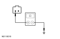
- Measure the
resistance
between:
| Positive
| Lead
| Negative
| Lead
| | Pin
| Circuit
| Pin
| Circuit
| |
|
| | C4230-6
| CRB06 (GN/WH)
| —
| Ground
| |
|
| | C4229-6
| CRB07 (BN)
| —
| Ground
|
 - Is the resistance greater than 10,000 ohms?
| Yes
For a LH concern, GO to
D11
.
For a RH concern, GO to
D12
.
No
REPAIR the circuit.
|
|
D5 CHECK THE SUSPECTED EXTERIOR MIRROR
/
LED FOR ILLUMINATION
|
|
- Ignition OFF.
- Disconnect:
C4230 (LH concern).
- Disconnect:
C4229 (RH concern).
- Connect a
fused jumper wire
between:
| Positive
| Lead
| Negative
| Lead
| | Pin
| Circuit
| Pin
| Circuit
| |
|
| | C4230-5
| CBP34 (VT/BN)
| C4230-6
| CRB06 (GN/WH)
| |
|
| | C4229-5
| CBP34 (VT/BN)
| C4229-6
| CRB07 (BN)
|
- Does the LED in question illuminate?
| Yes
For a LH concern, GO to
D11
.
For a RH concern, GO to
D12
.
No
GO to
D6
.
|
|
D6 CHECK THE EXTERIOR MIRROR GLASS
/
LED FOR AN OPEN
|
|
- Ignition OFF.
- Disconnect: Left Exterior Mirror
/
LED C516 (LH concern).
- Disconnect: Right Exterior Mirror
/
LED C625 (RH concern).
- Measure the
component side resistance
between:
| Positive
| Lead
| Negative
| Lead
| | Pin
| Circuit
| Pin
| Circuit
| |
|
| | C516-1
| —
| C516-2
| —
| |
|
| | C625-1
| —
| C625-2
| —
|
 - Is the resistance less than 2000 ohms?
| Yes
GO to
D7
.
No
INSTALL a new exterior mirror glass for the LED in question. REFER to
Section 501-09
.
|
|
D7 CHECK THE EXTERIOR MIRROR
/
LED SUPPLY CIRCUIT FOR AN OPEN
|
|
- Measure the
resistance
between:
| Positive
| Lead
| Negative
| Lead
| | Pin
| Circuit
| Pin
| Circuit
| |
|
| | C4230-6
| CRB06 (GN/WH)
| C516-1
| —
| |
|
| | C4229-6
| CRB07 (BN)
| C625-1
| —
|
 - Is the resistance greater than 3 ohms?
| Yes
GO to
D9
.
No
GO to
D8
.
|
|
D8 CHECK THE EXTERIOR MIRROR FOR AN OPEN
|
|
- Disconnect: Left Exterior Mirror C516 (LH concern).
- Disconnect: Right Exterior Mirror C625 (RH concern).
- Measure the
resistance
between:
| Positive
| Lead
| Negative
| Lead
| | Pin
| Circuit
| Pin
| Circuit
| |
|
| | C4230-6
| CRB06 (GN/WH)
| C516-15
| CRB06 (GN/WH)
| |
|
| | C4229-6
| CRB07 (BN)
| C625-15
| CRB07 (BN)
|
 - Is the resistance less than 3 ohms?
| Yes
INSTALL a new exterior mirror for the one in question. REFER to
Section 501-09
.
No
REPAIR the circuit in question.
|
|
D9 CHECK THE EXTERIOR MIRROR
/
LED GROUND CIRCUIT FOR AN OPEN
|
|
- Disconnect: Negative Battery Cable.
- Measure the
resistance
between:
| Positive
| Lead
| Negative
| Lead
| | Pin
| Circuit
| Pin
| Circuit
| |
|
| | C516-2
| —
| —
| Ground
| |
|
| | C625-2
| —
| —
| Ground
|
 - Is the resistance less than 3 ohms?
| Yes
For a LH concern, GO to
D11
.
For a RH concern, GO to
D12
.
No
GO to
D10
.
|
|
D10 CHECK THE EXTERIOR MIRROR GROUND CIRCUIT FOR AN OPEN
|
|
- Disconnect: Left Exterior Mirror C516 (LH concern).
- Disconnect: Right Exterior Mirror C625 (RH concern).
- Measure the
resistance
between:
| Positive
| Lead
| Negative
| Lead
| | Pin
| Circuit
| Pin
| Circuit
| |
|
| | C516-16
| GD233 (BK)
| —
| Ground
| |
|
| | C625-16
| GD348 (BK/YE)
| —
| Ground
|
 - Is the resistance less than 3 ohms?
| Yes
INSTALL a new exterior mirror for the one in question. REFER to
Section 501-09
.
No
REPAIR the circuit in question.
|
|
D11 CHECK FOR CORRECT
OPERATION
|
|
- Disconnect the
connector.
- Repair:
- corrosion (install new connector or terminals - clean module pins)
- damaged pins - install new terminals/pins
- pushed-out pins - install new pins as necessary
- Reconnect the
connector and make sure it seats and latches correctly.
- Operate the system and determine if the concern is still present.
- Is the concern still present?
| Yes
CHECK
for any applicable TSBs. If a TSB exists for this concern, DISCONTINUE this test and FOLLOW TSB instructions. If no TSBs address this concern, INSTALL a new
. REFER to
Side Obstacle Detection (SOD) Module
.
No
The system is operating correctly at this time. The concern may have been caused by module connections. ADDRESS the root cause of any connector or pin issues.
|
|
D12 CHECK FOR CORRECT
OPERATION
|
|
- Disconnect the
connector.
- Repair:
- corrosion (install new connector or terminals - clean module pins)
- damaged pins - install new terminals/pins
- pushed-out pins - install new pins as necessary
- Reconnect the
connector and make sure it seats and latches correctly.
- Operate the system and determine if the concern is still present.
- Is the concern still present?
| Yes
CHECK
for any applicable TSBs. If a TSB exists for this concern, DISCONTINUE this test and FOLLOW TSB instructions. If no TSBs address this concern, INSTALL a new
. REFER to
Side Obstacle Detection (SOD) Module
.
No
The system is operating correctly at this time. The concern may have been caused by module connections. ADDRESS the root cause of any connector or pin issues.
|
Pinpoint Test E: The
Does Not Respond To The Scan Tool Or Cannot Be Configured
Diagnostic Overview
Diagnostics in this manual assume a certain skill level and knowledge of Ford-specific diagnostic practices. Refer to Diagnostic Methods in
Section 100-00
for information about these practices.
Refer to Wiring Diagrams Cell
136
, Vehicle Emergency Messaging System for schematic and connector information.
Normal Operation and Fault Conditions
The
uses an address ground pin for configuration. The address ground is necessary so
or the
system can decipher between the
and the
during configuration. The
communicates over the
.
PINPOINT TEST E: THE
DOES NOT RESPOND TO THE SCAN TOOL OR CANNOT BE CONFIGURED
NOTICE:
Use the correct probe adapter(s) when making measurements. Failure to use the correct probe adapter(s) may damage the connector.
NOTE:
Failure to disconnect the battery when instructed will result in false resistance readings. Refer to
Section 414-01
.
| Test Step
| Result / Action to Take
|
|---|
|
E1 VERIFY THE
PASS THE NETWORK TEST
|
|
- Using a scan tool, perform the network test.
- Does the
pass the network test?
| Yes
The system is operating correctly at this time. The concern may have been caused by high network traffic or an intermittent problem.
No
GO to
E2
.
|
|
E2 CHECK THE
ADDRESS GROUND CIRCUIT FOR AN OPEN
|
|
- Disconnect: Negative Battery Cable.
- Disconnect:
C4229.
- Measure the
resistance
between:
| Positive
| Lead
| Negative
| Lead
| | Pin
| Circuit
| Pin
| Circuit
| | C4229-1
| GD351 (BK/GN)
| —
| Ground
|
- Is the resistance less than 3 ohms?
| Yes
CONFIGURE the
. REFER to
Section 418-01
.
No
REPAIR the circuit.
|
Pinpoint Test F: The Instrument Panel Cluster (IPC) Message Center Displays A Blocked Sensor Message
Diagnostic Overview
Diagnostics in this manual assume a certain skill level and knowledge of Ford-specific diagnostic practices. Refer to Diagnostic Methods in
Section 100-00
for information about these practices.
Refer to Wiring Diagrams Cell
136
, Vehicle Emergency Messaging System for schematic and connector information.
Normal Operation and Fault Conditions
A blocked sensor message indicates that there is an obstruction on the rear bumper cover fascia that does not allow the radar from the
and
to penetrate.
Refer to
and
Message Display in
Blind Spot Monitoring
.
Possible Sources
- Dirt, ice, or snow covered rear bumper fascia quarter panel
PINPOINT TEST F: THE
MESSAGE CENTER DISPLAYS A BLOCKED SENSOR MESSAGE
NOTICE:
Use the correct probe adapter(s) when making measurements. Failure to use the correct probe adapter(s) may damage the connector.
| Test Step
| Result / Action to Take
|
|---|
|
F1 INSPECT REAR BUMPER FASCIA COVER AND MODULE BRACKETS FOR DAMAGE
|
|
- Inspect for damage on the rear bumper fascia cover and module brackets.
- Is the rear bumper fascia cover and module brackets for damaged?
| Yes
For the rear bumper cover, REPAIR or REPLACE the rear bumper cover as necessary. REFER to
Section 501-19
.
For the
or the
bracket, REPAIR or REPLACE the
or the
bracket. REFER to
Side Obstacle Detection (SOD) Module
.
No
GO to
F2
.
|
|
F2 INSPECT THE
AND
FOR DEBRIS, MUD, SNOW OR ICE
|
|
- Inspect for debris, mud, snow or ice on the rear bumper fascia cover and
and
module housing.
- Is the rear bumper fascia cover and radar unit obstructed or blocked due to the concerns above?
| Yes
REMOVE and CLEAN the rear bumper fascia cover and module as necessary. Once the vehicle is cleaned, complete one key cycle and test drive the vehicle. The blocked module needs to detect an unblocked situation or 2 good detected vehicles or targets before clearing.
No
For an inoperative
, GO to
F3
.
For an inoperative
, GO to
F4
.
|
|
F3 CHECK FOR CORRECT
OPERATION
|
|
- Disconnect the
connector.
- Repair:
- corrosion (install new connector or terminals - clean module pins)
- damaged pins - install new terminals/pins
- pushed-out pins - install new pins as necessary
- Reconnect the
connector and make sure it seats and latches correctly.
- Operate the system and determine if the concern is still present.
- Is the concern still present?
| Yes
CHECK
for any applicable TSBs. If a TSB exists for this concern, DISCONTINUE this test and FOLLOW TSB instructions. If no TSBs address this concern, INSTALL a new
. REFER to
Side Obstacle Detection (SOD) Module
.
No
The system is operating correctly at this time. The concern may have been caused by module connections. ADDRESS the root cause of any connector or pin issues.
|
|
F4 CHECK FOR CORRECT
OPERATION
|
|
- Disconnect the
connector.
- Repair:
- corrosion (install new connector or terminals - clean module pins)
- damaged pins - install new terminals/pins
- pushed-out pins - install new pins as necessary
- Reconnect the
connector and make sure it seats and latches correctly.
- Operate the system and determine if the concern is still present.
- Is the concern still present?
| Yes
CHECK
for any applicable TSBs. If a TSB exists for this concern, DISCONTINUE this test and FOLLOW TSB instructions. If no TSBs address this concern, INSTALL a new
. REFER to
Side Obstacle Detection (SOD) Module
.
No
The system is operating correctly at this time. The concern may have been caused by module connections. ADDRESS the root cause of any connector or pin issues.
|
Pinpoint Test G: The Blind Spot Information System (BLIS®) and Cross Traffic Alert (CTA) System Cannot Be Turned Off In The Instrument Panel Cluster (IPC) Message Center
Diagnostic Overview
Diagnostics in this manual assume a certain skill level and knowledge of Ford-specific diagnostic practices. Refer to Diagnostic Methods in
Section 100-00
for information about these practices.
Refer to Wiring Diagrams Cell
136
, Vehicle Emergency Messaging System for schematic and connector information.
Normal Operation and Fault Conditions
The
and/or
system are turned off for one key cycle only when using the message center switches. Permanently disabling the
and/or
system is carried out in the Integrated Diagnostic System (IDS) programmable parameters menu.
Refer to
and
Message Display in
Blind Spot Monitoring
.
Possible Sources
- Wiring, terminals and connectors
PINPOINT TEST G: THE
AND
SYSTEM CANNOT BE TURNED OFF IN THE
MESSAGE CENTER
| Test Step
| Result / Action to Take
|
|---|
|
G1 VERIFY WHETHER A MYKEY® RESTRICTED KEY IS IN USE
|
|
- Verify if a MyKey® restricted key in use.
- Is a MyKey® restricted key is in use?
| Yes
The system is operating correctly at this time. INFORM the customer of normal operation. REFER to the Owners Literature.
No
GO to
G2
.
|
|
G2 CHECK THE DTCs FROM THE
SELF-TEST
|
|
- Using a scan tool, perform the
self-test.
- Are any DTCs recorded?
| Yes
REFER to
Section 413-01
.
No
GO to
G3
.
|
|
G3 CHECK THE DTCs FROM THE
AND
SELF-TESTS
|
|
- Using a scan tool, perform the
and
self-tests.
- Are any DTCs recorded?
| Yes
REFER to DTC Charts in this section.
No
GO to
G4
.
|
|
G4 CHECK THE MESSAGE CENTER FOR CORRECT OPERATION
|
|
- Check the message center for correct operation while turning the
and
system off and on.
- Does the message center operate correctly?
| Yes
The system is operating correctly at this time.
No
REFER to
Section 413-01
to diagnose the
message center is not operating correctly.
|
Pinpoint Test H: DTC U3000:44, 45, 46, 48, 49 or 4A
Diagnostic Overview
Diagnostics in this manual assume a certain skill level and knowledge of Ford-specific diagnostic practices. Refer to Diagnostic Methods in
Section 100-00
for information about these practices.
Refer to Wiring Diagrams Cell
136
, Vehicle Emergency Messaging System for schematic and connector information.
Normal Operation and Fault Conditions
On each ignition cycle, the
and
run a self-diagnostic check during which the exterior mirror
/
LEDs illuminate for 3 seconds then turn off indicating the system is operational. If a DTC fault is present, a system fault message is observed in the message center.
DTC Fault Trigger Conditions
| DTC
| Description
| Fault Trigger Conditions
|
|---|
| U3000:44
| Control Module: Data Memory Failure
| This DTC sets when the
or
detects an internal RAM memory failure.
|
| U3000:45
| Control Module: Program Memory Failure
| This DTC sets when the
or
detects an internal software failure.
|
| U3000:46
| Control Module: Calibration/Parameter Memory Failure
| This DTC sets when the
or
detects a failure with the EEPROM.
|
| U3000:48
| Control Module: Supervision Software Failure
| This DTC sets when the
or
detects a calibration failure.
|
| U3000:49
| Control Module: Internal Electronic Failure
| This DTC sets when the
or
detects an internal electronic communication failure.
|
| U3000:4A
| Control Module: Incorrect Component Installed
| This DTC sets when the
or
detects a weak or no sample radar signal.
|
PINPOINT TEST H: DTC U3000:44, 45, 46, 48, 49 OR 4A
| Test Step
| Result / Action to Take
|
|---|
|
H1 CHECK THE
and
FOR DTCs
|
|
- Ignition ON.
- Using a scan tool, clear the
and
DTCs.
- Ignition OFF.
- Wait 5 seconds
- Ignition ON.
- Using a scan tool, perform the
and
module self-tests.
- Are any U3000 DTCs present?
| Yes
INSTALL a new
or
. REFER to
Side Obstacle Detection (SOD) Module
.
No
The system is operating correctly at this time. The concern may have been caused by an intermittent problem.
|
Pinpoint Test I: An Exterior Mirror
/
LED Is Constantly On
Refer to Wiring Diagrams Cell
136
, Vehicle Emergency Messaging System for schematic and connector information.
Normal Operation and Fault Conditions
Refer to Exterior Mirror Indication in
Blind Spot Monitoring
.
DTC Fault Trigger Conditions
| DTC
| Description
| Fault Trigger Conditions
|
|---|
| B11D6:15
| Driver Display Alert LED: Circuit Short To Battery or Open
| This DTC sets when the
or
detect a short to battery voltage on the exterior mirror
/
LED supply circuit.
|
Possible Sources
- Wiring, terminals and connectors
- Exterior mirror
/
LED
PINPOINT TEST I: AN EXTERIOR MIRROR
/
LED IS CONSTANTLY ON
| Test Step
| Result / Action to Take
|
|---|
|
I1 VERIFY THE CUSTOMER'S CONCERN
|
|
- Carry out the diagnostic system check.
- Start the engine.
- Observe the left and right exterior mirror
/
LEDs.
- Do the left and right exterior mirror
/
LEDs illuminate and turn off after 3 seconds?
| Yes
The system is operating correctly at this time. The concern may have been caused by an intermittent problem. TEST the system for normal operation.
No
GO to
I2
.
|
|
I2 CHECK THE DTCs FROM
AND
SELF-TESTS
|
|
- Using a scan tool, perform the
and
self-tests.
- Are any
and
DTCs recorded?
| Yes
For DTC B11D6:15, GO to
I3
.
For all other DTCs, REFER to DTC Charts in this section.
No
GO to
I3
.
|
|
I3 CHECK THE EXTERIOR MIRROR
/
LED SUPPLY CIRCUIT FOR A SHORT TO VOLTAGE
|
|
- Ignition OFF.
- Disconnect:
C4230 (LH concern).
- Disconnect:
C4229 (RH concern).
- Ignition ON.
- Measure the
voltage
between:
| Positive
| Lead
| Negative
| Lead
| | Pin
| Circuit
| Pin
| Circuit
| |
|
| | C4230-6
| CRB06 (GN/WH)
| —
| Ground
| |
|
| | C4229-6
| CRB07 (BN)
| —
| Ground
|
- Is any voltage present?
| Yes
GO to
I4
.
No
For a LH concern, GO to
I5
. For a RH concern, GO to
I6
.
|
|
I4 CHECK THE EXTERIOR MIRROR FOR A SHORT TO VOLTAGE
|
|
- Ignition OFF.
- Disconnect: Left Exterior Mirror C516 (LH concern).
- Disconnect: Right Exterior Mirror C622 (RH concern).
- Ignition ON.
- Measure the
voltage
between:
| Positive
| Lead
| Negative
| Lead
| | Pin
| Circuit
| Pin
| Circuit
| |
|
| | C4230-6
| CRB06 (GN/WH)
| —
| Ground
| |
|
| | C4229-6
| CRB07 (BN)
| —
| Ground
|
- Is any voltage present?
| Yes
REPAIR the circuit.
No
INSTALL a new exterior mirror for the one in question. REFER to
Section 501-09
.
|
|
I5 CHECK FOR CORRECT
OPERATION
|
|
- Disconnect the
connector.
- Repair:
- corrosion (install new connector or terminals - clean module pins)
- damaged pins - install new terminals/pins
- pushed-out pins - install new pins as necessary
- Reconnect the
connector and make sure it seats and latches correctly.
- Operate the system and determine if the concern is still present.
- Is the concern still present?
| Yes
CHECK
for any applicable TSBs. If a TSB exists for this concern, DISCONTINUE this test and FOLLOW TSB instructions. If no TSBs address this concern, INSTALL a new
. REFER to
Side Obstacle Detection (SOD) Module
.
No
The system is operating correctly at this time. The concern may have been caused by module connections. ADDRESS the root cause of any connector or pin issues.
|
|
I6 CHECK FOR CORRECT
OPERATION
|
|
- Disconnect the
connector.
- Repair:
- corrosion (install new connector or terminals - clean module pins)
- damaged pins - install new terminals/pins
- pushed-out pins - install new pins as necessary
- Reconnect the
connector and make sure it seats and latches correctly.
- Operate the system and determine if the concern is still present.
- Is the concern still present?
| Yes
CHECK
for any applicable TSBs. If a TSB exists for this concern, DISCONTINUE this test and FOLLOW TSB instructions. If no TSBs address this concern, INSTALL a new
. REFER to
Side Obstacle Detection (SOD) Module
.
No
The system is operating correctly at this time. The concern may have been caused by module connections. ADDRESS the root cause of any connector or pin issues.
|
Pinpoint Test J: DTC U0140:00
Diagnostic Overview
Diagnostics in this manual assume a certain skill level and knowledge of Ford-specific diagnostic practices. Refer to Diagnostic Methods in
Section 100-00
for information about these practices.
Normal Operation and Fault Conditions
Refer to Network Message Chart in
Blind Spot Monitoring
.
DTC Fault Trigger Conditions
| DTC
| Description
| Fault Trigger Conditions
|
|---|
| U0140:00
| Lost Communication With Body Control Module: No Sub Type Information
| Set by the
and
when network messages are missing from the
with the ignition in RUN.
|
PINPOINT TEST J: DTC U0140:00
| Test Step
| Result / Action to Take
|
|---|
|
J1 VERIFY THE CUSTOMER CONCERN
|
|
- Ignition ON.
- Verify that there is an observable symptom present.
- Is an observable symptom present?
| Yes
GO to
J2
.
No
The system is operating normally at this time. The DTC may have been set due to high network traffic or an intermittent fault condition.
|
|
J2 CHECK THE COMMUNICATION NETWORK
|
|
- Ignition ON.
- Using a scan tool, perform the network test.
- Does the
pass the network test?
| Yes
GO to
J3
.
No
REFER to
Section 418-00
, The
Does Not Respond To The Scan Tool.
|
|
J3 RECHECK THE
OR THE
DTCs
|
|
- Using a scan tool, perform the
or the
self-tests.
- Is DTC U0140:00 still present?
| Yes
GO to
J4
.
No
The system is operating correctly at this time. The DTC may have been set due to high network traffic or an intermittent fault condition.
|
|
J4 CHECK FOR LOST COMMUNICATION DTCs
|
|
- Ignition ON.
- Clear continuous DTCs from all modules.
- Ignition OFF.
- Ignition ON.
- Wait at least 10 seconds.
- Retrieve all continuous DTCs from all modules.
- Is DTC U0140:00 set in any module?
| Yes
GO to
J5
.
No
If DTC U0140:00 only sets in
, GO to
J6
. If DTC U0140:00 only sets in
, GO to
J7
.
|
|
J5 CHECK FOR CORRECT
OPERATION
|
|
- Disconnect the
connectors.
- Repair:
- corrosion (install new connector or terminals - clean module pins)
- damaged pins - install new terminals/pins
- pushed-out pins - install new pins as necessary
- Reconnect the
connectors and make sure they seat and latch correctly.
- Operate the system and determine if the concern is still present.
- Is the concern still present?
| Yes
CHECK
for any applicable TSBs. If a TSB exists for this concern, DISCONTINUE this test and FOLLOW TSB instructions. If no TSBs address this concern, INSTALL a new
. REFER to
Section 419-10
.
No
The system is operating correctly at this time. The concern may have been caused by module connections. ADDRESS the root cause of any connector or pin issues.
|
|
J6 CHECK FOR CORRECT
OPERATION
|
|
- Disconnect the
connector.
- Repair:
- corrosion (install new connector or terminals - clean module pins)
- damaged pins - install new terminals/pins
- pushed-out pins - install new pins as necessary
- Reconnect the
connector and make sure it seats and latches correctly.
- Operate the system and determine if the concern is still present.
- Is the concern still present?
| Yes
CHECK
for any applicable TSBs. If a TSB exists for this concern, DISCONTINUE this test and FOLLOW TSB instructions. If no TSBs address this concern, INSTALL a new
. REFER to
Side Obstacle Detection (SOD) Module
.
No
The system is operating correctly at this time. The concern may have been caused by module connections. ADDRESS the root cause of any connector or pin issues.
|
|
J7 CHECK FOR CORRECT
OPERATION
|
|
- Disconnect the
connector.
- Repair:
- corrosion (install new connector or terminals - clean module pins)
- damaged pins - install new terminals/pins
- pushed-out pins - install new pins as necessary
- Reconnect the
connector and make sure it seats and latches correctly.
- Operate the system and determine if the concern is still present.
- Is the concern still present?
| Yes
CHECK
for any applicable TSBs. If a TSB exists for this concern, DISCONTINUE this test and FOLLOW TSB instructions. If no TSBs address this concern, INSTALL a new
. REFER to
Side Obstacle Detection (SOD) Module
.
No
The system is operating correctly at this time. The concern may have been caused by module connections. ADDRESS the root cause of any connector or pin issues.
|