
SGT27000

NUD105-R025D
SECTION 501-03: Body Closures
| 2014 Flex Workshop Manual
|
DIAGNOSIS AND TESTING
| Procedure revision date: 05/02/2013
|
 | Circuit Tester/Test Light
SGT27000 |
 | Flex Probe Kit
NUD105-R025D |
DTC Charts
Diagnostics in this manual assume a certain skill level and knowledge of Ford-specific diagnostic practices. Refer to Diagnostic Methods in Section 100-00 for information about these practices.
BCM DTC Chart
| DTC | Description | Action |
|---|---|---|
| B12E8:11 | Liftgate/Tailgate Control/Release Switch: Circuit Short To Ground | GO to Pinpoint Test B . |
| All other DTCs | — | REFER to Section 419-10 . |
RFA Module DTC Chart
| DTC | Description | Action |
|---|---|---|
| B113E:11 | External Boot/Trunk Release Switch: Circuit Short To Ground | GO to Pinpoint Test B . |
| All other DTCs | — | REFER to Section 419-10 . |
LTM DTC Chart
| DTC | Description | Action |
|---|---|---|
| B107D | Obstacle Detected While Closing | GO to Pinpoint Test D . |
| B1105 | Rear Open/Close Switch Active During Self Test | GO to Pinpoint Test B . |
| B1179 | Latch Motor Circuit Short to Battery | GO to Pinpoint Test A . |
| B117A | Latch Motor Circuit Short to Ground | GO to Pinpoint Test A . |
| B117B | Latch Motor Circuit Open | GO to Pinpoint Test A . |
| B117C | Latch Centering Switch Invalid | GO to Pinpoint Test J . |
| B1317 | Battery Voltage High | GO to Pinpoint Test N . |
| B1318 | Battery Voltage Low | GO to Pinpoint Test O . |
| B1342 | ECU Is Faulted | CLEAR the DTCs. REPEAT the self-test. If DTC B1342 returns, INSTALL a new LTM . REFER to Liftgate/Trunk Module (LTM) . |
| B2019 | Liftgate Exceeded Time Allowed to Cinch Door | GO to Pinpoint Test C . |
| B201A | Power System Disabled Due to High Manual Closing Speed | GO to Pinpoint Test H . |
| B236A | Chime Output Circuit Open | GO to Pinpoint Test I . |
| B2418 | Sensor Power Short to Ground | GO to Pinpoint Test K . |
| B2419 | Sensor 1 Invalid | GO to Pinpoint Test K . |
| B2420 | Sensor 2 Invalid | GO to Pinpoint Test K . |
| B2552 | Vbatt 2 Circuit Open | GO to Pinpoint Test A . |
| B2699 | Left Pinch Strip Open or Short to Battery | GO to Pinpoint Test F . |
| B2700 | Right Pinch Strip Open or Short to Battery | GO to Pinpoint Test F . |
| B2701 | Left Pinch Strip Stuck Active | GO to Pinpoint Test F . |
| B2702 | Right Pinch Strip Stuck Active | GO to Pinpoint Test F . |
| B2703 | Open/Close Switch Stuck Active | GO to Pinpoint Test B . |
| B2718 | Liftgate/Decklid Ajar Output Short to Battery | REFER to Section 417-02 . |
| B2721 | Liftgate/Decklid Ajar Output Short to Ground or Open | REFER to Section 417-02 . |
| B2819 | Gate Motor Circuit Short to Battery | GO to Pinpoint Test A . |
| B2903 | Chime Output Circuit Short to Battery | GO to Pinpoint Test I . |
| B2908 | Latch Switch Invalid | GO to Pinpoint Test L . |
| B2935 | Drive Unit Failure | GO to Pinpoint Test M . |
| B2936 | Gate Motor Open | GO to Pinpoint Test A . |
| B2937 | Gate Motor Short to Ground | GO to Pinpoint Test A . |
| B2940 | Chime Output Circuit Short to Ground | GO to Pinpoint Test I . |
| U0140 | Lost Communication With Body Control Module (GEM) | GO to Pinpoint Test P . |
| U0155 | Lost Communication With Instrument Panel Cluster (IC) Control Module | GO to Pinpoint Test Q . |
| U2050 | No Application Present | CLEAR the DTCs. REPEAT the self-test. If DTC U2050 returns, INSTALL a new LTM . REFER to Liftgate/Trunk Module (LTM) . |
| U2051 | One or More Calibration Files Missing / Corrupt | CLEAR the DTCs. REPEAT the self-test. If DTC U2051 returns, INSTALL a new LTM . REFER to Liftgate/Trunk Module (LTM) . |
| U2471 | Unexpected PRNDL State | VERIFY the transmission gear selector (PRNDL) is in PARK. CLEAR the DTCs. REPEAT the self-test. If DTC U2471 is retrieved again, RETRIEVE and FOLLOW non-network DTCs from the IPC module. REFER to Section 413-01 . If no DTCs are present, INSTALL a new LTM . REFER to Liftgate/Trunk Module (LTM) . |
| U2472 | Unexpected Ignition State | VERIFY the ignition is ON. CLEAR the DTCs. REPEAT the self-test. If DTC U2472 is retrieved again, RETRIEVE and FOLLOW non-network DTCs from the BCM . REFER to Section 419-10 . If no DTCs are present, INSTALL a new LTM . REFER to Liftgate/Trunk Module (LTM) . |
| U2473 | Unexpected Vehicle Speed (VSS) | CLEAR the DTCs. REPEAT the self-test. If DTC U2473 is retrieved again, RETRIEVE and FOLLOW non-network DTCs from the IPC . REFER to Section 413-01 . If no related DTCs, INSTALL a new LTM . REFER to Liftgate/Trunk Module (LTM) . |
Symptom Chart
Diagnostics in this manual assume a certain skill level and knowledge of Ford-specific diagnostic practices. Refer to Diagnostic Methods in Section 100-00 for information about these practices.
| Condition | Possible Sources | Action |
|---|---|---|
|
| |
|
| |
|
|
|
|
|
|
|
| |
|
|
|
|
|
|
|
| |
|
| |
|
| |
|
| |
|
| |
|
| |
|
|
|
Pinpoint Tests
Pinpoint Test A: The Power Liftgate is Inoperative
Diagnostics in this manual assume a certain skill level and knowledge of Ford-specific diagnostic practices. Refer to Diagnostic Methods in Section 100-00 for information about these practices.
Refer to Wiring Diagrams Cell 109 , Power Liftgate for schematic and connector information.
Refer to System Operation - Power Liftgate in Body Closures .
Refer to Component Description - Power Liftgate Latch in Body Closures .
Refer to Component Description - Power Liftgate Motor in Body Closures .
LTM DTC Fault Trigger Conditions
| DTC | Description | Fault Trigger Conditions |
|---|---|---|
| B1179 | Latch Motor Circuit Short to Battery | Sets when the LTM detects a short to voltage from the latch motor circuit(s). |
| B117A | Latch Motor Circuit Short to Ground | Sets when the LTM detects a short to ground from the latch motor circuit(s). |
| B117B | Latch Motor Circuit Open | Sets when the LTM detects an open from the latch motor circuit(s). The LTM determines an open is present when it detects no current change upon latch motor activation. |
| B2552 | Vbatt 2 Circuit Open | Sets when the LTM detects less than 4 volts from the high current voltage feed circuit and the logic voltage feed circuit is greater than 8 volts. |
| B2819 | Gate Motor Circuit Short to Battery | Sets when the LTM detects a short to battery from a power liftgate motor circuit. |
| B2936 | Gate Motor Open | Sets when the LTM detects an open from a power liftgate motor circuit. The LTM determines an open is present when it detects no current change upon liftgate motor activation. |
| B2937 | Gate Motor Short to Ground | Sets when the LTM detects a short to ground from a power liftgate motor circuit. |
Visual Inspection and Diagnostic Pre-checks
| Test Step | Result / Action to Take | ||||||||||||||||||||||||
|---|---|---|---|---|---|---|---|---|---|---|---|---|---|---|---|---|---|---|---|---|---|---|---|---|---|
| A1 CHECK THE OPERATION OF ALL THE POWER LIFTGATE INPUTS | |||||||||||||||||||||||||
NOTE: Make sure the power liftgate is enabled in the vehicle message center. | Yes
GO to Symptom Chart . No GO to A2 . | ||||||||||||||||||||||||
| A2 RETRIEVE THE DTCs FROM THE LTM | |||||||||||||||||||||||||
| Yes
For DTC B2552, GO to A3 . For DTC B1179, B117A, B117B, B2819, B2936, or B2937, GO to A7 . For all other LTM DTCs, REFER to the LTM DTC Chart in this section. No GO to A3 . | ||||||||||||||||||||||||
| A3 CHECK THE LTM VOLTAGE SUPPLY CIRCUITS FOR AN OPEN | |||||||||||||||||||||||||
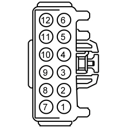 | Yes
GO to A4 . No VERIFY BCM fuse 8 (10A) or BJB fuse 7 (30A) is OK. If OK, REPAIR the circuit in question. If not OK, REFER to the Wiring Diagrams manual to identify the possible causes of the circuit short. | ||||||||||||||||||||||||
| A4 CHECK THE LTM GROUND CIRCUIT FOR AN OPEN | |||||||||||||||||||||||||
 | Yes
GO to A5 . No REPAIR the circuit. | ||||||||||||||||||||||||
| A5 CHECK THE DETENT AND FORKBOLT SWITCH PIDs | |||||||||||||||||||||||||
| Yes
GO to A6 . No GO to Pinpoint Test L . | ||||||||||||||||||||||||
| A6 CHECK THE LIFTGATE POSITION SENSOR (OPT_SEN_1) AND (OPT_SEN_2) PIDs | |||||||||||||||||||||||||
| Yes
GO to A7 . No GO to Pinpoint Test K . | ||||||||||||||||||||||||
| A7 CHECK THE MOTOR AND LATCH CIRCUITS FOR A SHORT TO VOLTAGE | |||||||||||||||||||||||||
 | Yes
REPAIR the circuit in question. No GO to A8 . | ||||||||||||||||||||||||
| A8 CHECK THE MOTOR AND LATCH CIRCUITS FOR A SHORT TO GROUND | |||||||||||||||||||||||||
 | Yes
GO to A9 . No REPAIR the circuit in question. | ||||||||||||||||||||||||
| A9 CHECK THE MOTOR AND LATCH CIRCUITS FOR AN OPEN | |||||||||||||||||||||||||
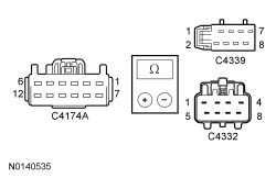 | Yes
GO to A10 . No REPAIR the circuit in question. | ||||||||||||||||||||||||
| A10 CHECK THE UNLATCH OPERATION | |||||||||||||||||||||||||

 | Yes
REMOVE the jumper wire. LEAVE the liftgate unlatched. GO to A11 . No REMOVE the jumper wire. INSTALL a new power liftgate latch. REFER to Section 501-14A or Section 501-14B . | ||||||||||||||||||||||||
| A11 CHECK THE POWER LIFTGATE MOTOR OPERATION | |||||||||||||||||||||||||

 | Yes
GO to A12 . No INSTALL a new power liftgate motor. REFER to Power Liftgate Motor . | ||||||||||||||||||||||||
| A12 CHECK FOR CORRECT LTM OPERATION | |||||||||||||||||||||||||
| Yes
CHECK On-Line Automotive Service Information System (OASIS) for any applicable TSBs . If a TSB exists for this concern, DISCONTINUE this test and FOLLOW TSB instructions. If no TSBs address this concern, INSTALL a new LTM . REFER to Liftgate/Trunk Module (LTM) . No The system is operating correctly at this time. The concern may have been caused by module connections. ADDRESS the root cause of any connector or pin issues. | ||||||||||||||||||||||||
Pinpoint Test B: The Power Liftgate Is Inoperative From Any Power Liftgate Control Switch
Diagnostics in this manual assume a certain skill level and knowledge of Ford-specific diagnostic practices. Refer to Diagnostic Methods in Section 100-00 for information about these practices.
Refer to Wiring Diagrams Cell 109 , Power Liftgate for schematic and connector information.
Refer to System Operation - Power Liftgate in Body Closures .
Refer to Component Description - Front Power Liftgate Switch in Body Closures .
Refer to Component Description - Rear Power Liftgate Switch in Body Closures .
Refer to Component Description - Liftgate Release Switch in Body Closures .
Refer to Component Description - Liftgate/Trunk Module (LTM) in Body Closures .
LTM DTC Fault Trigger Conditions
| DTC | Description | Fault Trigger Conditions |
|---|---|---|
| B1105 | Rear Open/Close Switch Active During Self Test | Sets when the LTM detects a short to ground from the rear power liftgate switch input circuit. |
| B2703 | Open/Close Switch Stuck Active | Sets when the LTM detects a short to ground from the front power liftgate switch input circuit. |
BCM DTC Fault Trigger Conditions
| DTC | Description | Fault Trigger Conditions |
|---|---|---|
| B12E8:11 | Liftgate/Tailgate Control/Release Switch: Circuit Short To Ground | Sets when the BCM detects a short to ground from the liftgate release switch input circuit. |
RFA Module DTC Fault Trigger Conditions
| DTC | Description | Fault Trigger Conditions |
|---|---|---|
| B113E:11 | External Boot/Trunk Release Switch: Circuit Short To Ground | Sets when the RFA module detects a short to ground from the liftgate release switch input circuit. |
| Test Step | Result / Action to Take | ||||||||||||||||||||||||||||||||||||||||||||||||
|---|---|---|---|---|---|---|---|---|---|---|---|---|---|---|---|---|---|---|---|---|---|---|---|---|---|---|---|---|---|---|---|---|---|---|---|---|---|---|---|---|---|---|---|---|---|---|---|---|---|
| B1 CHECK THE OPERATION OF THE POWER LIFTGATE FROM ALL THE SWITCH INPUTS | |||||||||||||||||||||||||||||||||||||||||||||||||
NOTE: Make sure the power liftgate is enabled in the message center. | Yes
GO to B2 . No GO to Pinpoint Test A . | ||||||||||||||||||||||||||||||||||||||||||||||||
| B2 CHECK FOR LIFTGATE SWITCH DTCs FROM THE LTM | |||||||||||||||||||||||||||||||||||||||||||||||||
| Yes
GO to B3 . No If not equipped with IA , GO to B5 . If equipped with IA , GO to B8 . | ||||||||||||||||||||||||||||||||||||||||||||||||
| B3 CHECK THE POWER LIFTGATE SWITCH FOR A SHORT TO GROUND | |||||||||||||||||||||||||||||||||||||||||||||||||
| Yes
GO to B4 . No INSTALL a new front or rear power liftgate switch in question. | ||||||||||||||||||||||||||||||||||||||||||||||||
| B4 CHECK THE POWER LIFTGATE SWITCH INPUT CIRCUIT FOR A SHORT TO GROUND | |||||||||||||||||||||||||||||||||||||||||||||||||
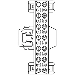
 | Yes
GO to B16 . No REPAIR the circuit in question. | ||||||||||||||||||||||||||||||||||||||||||||||||
| B5 CHECK FOR DTC B12E8:11 FROM THE BCM | |||||||||||||||||||||||||||||||||||||||||||||||||
| Yes
GO to B6 . No GO to B11 . | ||||||||||||||||||||||||||||||||||||||||||||||||
| B6 CHECK THE LIFTGATE RELEASE SWITCH FOR A SHORT TO GROUND (WITHOUT IA ) | |||||||||||||||||||||||||||||||||||||||||||||||||
| Yes
GO to B7 . No INSTALL a new liftgate release switch. REFER to Section 501-14A . | ||||||||||||||||||||||||||||||||||||||||||||||||
| B7 CHECK THE LIFTGATE RELEASE SWITCH INPUT CIRCUIT FOR A SHORT TO GROUND (WITHOUT IA ) | |||||||||||||||||||||||||||||||||||||||||||||||||
 | Yes
GO to B15 . No REPAIR the circuit. | ||||||||||||||||||||||||||||||||||||||||||||||||
| B8 CHECK FOR DTC B113E:11 FROM THE RFA MODULE | |||||||||||||||||||||||||||||||||||||||||||||||||
| Yes
GO to B9 . No GO to B11 . | ||||||||||||||||||||||||||||||||||||||||||||||||
| B9 CHECK THE LIFTGATE RELEASE SWITCH FOR A SHORT TO GROUND (WITH IA ) | |||||||||||||||||||||||||||||||||||||||||||||||||
| Yes
GO to B10 . No INSTALL a new liftgate release switch. REFER to Section 501-14B . | ||||||||||||||||||||||||||||||||||||||||||||||||
| B10 CHECK THE LIFTGATE RELEASE SWITCH INPUT CIRCUIT FOR A SHORT TO GROUND (WITH IA ) | |||||||||||||||||||||||||||||||||||||||||||||||||
 | Yes
GO to B14 . No REPAIR the circuit. | ||||||||||||||||||||||||||||||||||||||||||||||||
| B11 BYPASS THE SUSPECT SWITCH | |||||||||||||||||||||||||||||||||||||||||||||||||
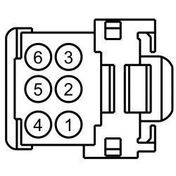
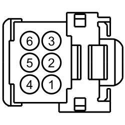
 | Yes
INSTALL a new switch in question. No GO to B12 . | ||||||||||||||||||||||||||||||||||||||||||||||||
| B12 CHECK THE POWER LIFTGATE SWITCH GROUND CIRCUIT FOR AN OPEN | |||||||||||||||||||||||||||||||||||||||||||||||||


 | Yes
GO to B13 . No REPAIR the circuit. | ||||||||||||||||||||||||||||||||||||||||||||||||
| B13 CHECK THE POWER LIFTGATE SWITCH INPUT CIRCUIT FOR AN OPEN | |||||||||||||||||||||||||||||||||||||||||||||||||
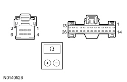

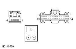
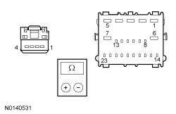 | Yes
For a front or rear liftgate switch, GO to B16 . For the liftgate release switch on vehicles not equipped with IA , GO to B15 . For the liftgate release switch on vehicles equipped with IA , GO to B14 . No REPAIR the circuit. | ||||||||||||||||||||||||||||||||||||||||||||||||
| B14 CHECK FOR CORRECT RFA MODULE OPERATION | |||||||||||||||||||||||||||||||||||||||||||||||||
| Yes
CHECK On-Line Automotive Service Information System (OASIS) for any applicable TSBs . If a TSB exists for this concern, DISCONTINUE this test and FOLLOW TSB instructions. If no TSBs address this concern, INSTALL a new RFA module. REFER to Section 419-10 . No The system is operating correctly at this time. The concern may have been caused by module connections. ADDRESS the root cause of any connector or pin issues. | ||||||||||||||||||||||||||||||||||||||||||||||||
| B15 CHECK FOR CORRECT BCM OPERATION | |||||||||||||||||||||||||||||||||||||||||||||||||
| Yes
CHECK On-Line Automotive Service Information System (OASIS) for any applicable TSBs . If a TSB exists for this concern, DISCONTINUE this test and FOLLOW TSB instructions. If no TSBs address this concern, INSTALL a new BCM . REFER to Section 419-10 . No The system is operating correctly at this time. The concern may have been caused by module connections. ADDRESS the root cause of any connector or pin issues. | ||||||||||||||||||||||||||||||||||||||||||||||||
| B16 CHECK FOR CORRECT LTM OPERATION | |||||||||||||||||||||||||||||||||||||||||||||||||
| Yes
CHECK On-Line Automotive Service Information System (OASIS) for any applicable TSBs . If a TSB exists for this concern, DISCONTINUE this test and FOLLOW TSB instructions. If no TSBs address this concern, INSTALL a new LTM . REFER to Liftgate/Trunk Module (LTM) . No The system is operating correctly at this time. The concern may have been caused by module connections. ADDRESS the root cause of any connector or pin issues. | ||||||||||||||||||||||||||||||||||||||||||||||||
Pinpoint Test C: The Power Liftgate Stops In The Secondary Latch Position
Diagnostics in this manual assume a certain skill level and knowledge of Ford-specific diagnostic practices. Refer to Diagnostic Methods in Section 100-00 for information about these practices.
Refer to System Operation - Power Liftgate in Body Closures .
Refer to Component Description - Power Liftgate Latch in Body Closures .
LTM DTC Fault Trigger Conditions
| DTC | Description | Fault Trigger Conditions |
|---|---|---|
| B2019 | Liftgate Exceeded Time Allowed to Cinch Door | Sets when the LTM detects the liftgate cinching sequence has been active for more than 5 seconds. |
| Test Step | Result / Action to Take | ||||||||||||
|---|---|---|---|---|---|---|---|---|---|---|---|---|---|
| C1 CHECK THE MANUAL OPERATION OF THE LIFTGATE | |||||||||||||
| Yes
GO to C2 . No REPAIR as necessary. | ||||||||||||
| C2 CHECK THE LIFTGATE LATCH AND STRIKER ALIGNMENT | |||||||||||||
NOTE: Make sure to inspect the underside of the striker bridge for witness marks. | Yes
GO to C3 . No ALIGN the liftgate and striker. REFER to Liftgate Alignment . | ||||||||||||
| C3 CHECK THE DETENT AND FORKBOLT SWITCH PIDs | |||||||||||||
| Yes
GO to C4 . No GO to Pinpoint Test L . | ||||||||||||
| C4 CHECK FOR CORRECT LTM OPERATION | |||||||||||||
| Yes
CHECK On-Line Automotive Service Information System (OASIS) for any applicable TSBs . If a TSB exists for this concern, DISCONTINUE this test and FOLLOW TSB instructions. If no TSBs address this concern, INSTALL a new LTM . REFER to Liftgate/Trunk Module (LTM) . No The system is operating correctly at this time. The concern may have been caused by module connections. ADDRESS the root cause of any connector or pin issues. |
Pinpoint Test D: The Power Liftgate Reverses During The Power Close Operation
Diagnostics in this manual assume a certain skill level and knowledge of Ford-specific diagnostic practices. Refer to Diagnostic Methods in Section 100-00 for information about these practices.
Refer to System Operation - Power Liftgate in Body Closures .
| Test Step | Result / Action to Take | ||||||||||||
|---|---|---|---|---|---|---|---|---|---|---|---|---|---|
| D1 CHECK THE MANUAL OPERATION OF THE LIFTGATE | |||||||||||||
| Yes
GO to D2 . No REPAIR as necessary. | ||||||||||||
| D2 CHECK THE LIFTGATE POSITION SENSOR (OPT_SEN_1) AND (OPT_SEN_2) PIDs | |||||||||||||
| Yes
GO to D3 . No GO to Pinpoint Test K . | ||||||||||||
| D3 CHECK THE DETENT AND FORKBOLT SWITCH PIDs | |||||||||||||
| Yes
GO to D4 . No GO to Pinpoint Test L . | ||||||||||||
| D4 CHECK FOR CORRECT LTM OPERATION | |||||||||||||
| Yes
CHECK On-Line Automotive Service Information System (OASIS) for any applicable TSBs . If a TSB exists for this concern, DISCONTINUE this test and FOLLOW TSB instructions. If no TSBs address this concern, INSTALL a new LTM . REFER to Liftgate/Trunk Module (LTM) . No The system is operating correctly at this time. The concern may have been caused by module connections. ADDRESS the root cause of any connector or pin issues. |
Pinpoint Test E: The Power Liftgate Pinch Strip Does Not Stop Or Reverse The Liftgate
Diagnostics in this manual assume a certain skill level and knowledge of Ford-specific diagnostic practices. Refer to Diagnostic Methods in Section 100-00 for information about these practices.
Refer to System Operation - Power Liftgate in Body Closures .
Refer to Component Description - Pinch Switch Strip in Body Closures .
LTM DTC Fault Trigger Conditions
| DTC | Description | Fault Trigger Conditions |
|---|---|---|
| B107D | Obstacle Detected While Closing | Sets when the LTM detects an obstacle during a power close. |
Visual Inspection and Diagnostic Pre-checks
| Test Step | Result / Action to Take |
|---|---|
| E1 CHECK FOR PINCH STRIP RELATED DTCs FROM THE LTM | |
| Yes
GO to Pinpoint Test F . No GO to E2 . |
| E2 CHECK THE LIFTGATE LEFT/RIGHT PINCH STRIP INPUT | |
| Yes
GO to E3 . No INSTALL a new pinch strip switch in question. REFER to Pinch Strip Switch . |
| E3 CHECK FOR CORRECT LTM OPERATION | |
| Yes
CHECK On-Line Automotive Service Information System (OASIS) for any applicable TSBs . If a TSB exists for this concern, DISCONTINUE this test and FOLLOW TSB instructions. If no TSBs address this concern, INSTALL a new LTM . REFER to Liftgate/Trunk Module (LTM) . No The system is operating correctly at this time. The concern may have been caused by module connections. ADDRESS the root cause of any connector or pin issues. |
Pinpoint Test F: The Power Liftgate Does Not Power Close (Power Open OK)
Diagnostics in this manual assume a certain skill level and knowledge of Ford-specific diagnostic practices. Refer to Diagnostic Methods in Section 100-00 for information about these practices.
Refer to Wiring Diagrams Cell 109 , Power Liftgate for schematic and connector information.
Refer to System Operation - Power Liftgate in Body Closures .
Refer to Component Description - Pinch Strip Switch in Body Closures .
LTM DTC Fault Trigger Conditions
| DTC | Description | Fault Trigger Conditions |
|---|---|---|
| B2699 | Left Pinch Strip Open or Short to Battery | Sets when the LTM detects more than 3.7 volts from the left pinch strip input circuit. |
| B2700 | Right Pinch Strip Open or Short to Battery | Sets when the LTM detects more than 3.7 volts from the right pinch strip input circuit. |
| B2701 | Left Pinch Strip Stuck Active | Sets when the LTM detects less than 0.5 volt from the left pinch strip input circuit. |
| B2702 | Right Pinch Strip Stuck Active | Sets when the LTM detects than 0.5 volt from the right pinch strip input circuit. |
Visual Inspection and Diagnostic Pre-checks
| Test Step | Result / Action to Take | ||||||||||||||||
|---|---|---|---|---|---|---|---|---|---|---|---|---|---|---|---|---|---|
| F1 CHECK THE MANUAL OPERATION OF THE LIFTGATE | |||||||||||||||||
| Yes
GO to F2 . No REPAIR or ALIGN as necessary. REFER to Liftgate Alignment . | ||||||||||||||||
| F2 CHECK THE LIFTGATE PINCH STRIP INPUT TO THE LTM | |||||||||||||||||
| Yes
GO to F11 . No GO to F3 . | ||||||||||||||||
| F3 CHECK FOR A VOLTAGE SIGNAL TO THE SUSPECT PINCH STRIP SWITCH | |||||||||||||||||
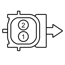 | Yes
GO to F7 . No GO to F4 . | ||||||||||||||||
| F4 CHECK THE PINCH STRIP SIGNAL CIRCUIT FOR A SHORT TO VOLTAGE | |||||||||||||||||
 | Yes
REPAIR the circuit. No GO to F5 . | ||||||||||||||||
| F5 CHECK THE PINCH STRIP SIGNAL CIRCUIT FOR A SHORT TO GROUND | |||||||||||||||||
 | Yes
GO to F6 . No REPAIR the circuit. | ||||||||||||||||
| F6 CHECK THE PINCH STRIP SIGNAL CIRCUIT FOR AN OPEN | |||||||||||||||||
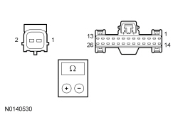 | Yes
GO to F12 . No REPAIR the circuit. | ||||||||||||||||
| F7 CHECK THE SUSPECT PINCH STRIP RESISTANCE | |||||||||||||||||
 | Yes
GO to F8 . No INSTALL a new pinch strip switch in question. REFER to Pinch Strip Switch . | ||||||||||||||||
| F8 CHECK THE PINCH STRIP RETURN CIRCUIT | |||||||||||||||||
 | Yes
INSTALL a new pinch strip switch in question. REFER to Pinch Strip Switch . No GO to F9 . | ||||||||||||||||
| F9 CHECK THE PINCH STRIP RETURN CIRCUIT FOR SHORT TO VOLTAGE | |||||||||||||||||
 | Yes
GO to F10 . No REPAIR the circuit. | ||||||||||||||||
| F10 CHECK THE PINCH STRIP RETURN CIRCUIT FOR AN OPEN | |||||||||||||||||
 | Yes
GO to F12 . No REPAIR the circuit. | ||||||||||||||||
| F11 CHECK THE DETENT AND FORKBOLT SWITCH PIDs | |||||||||||||||||
| Yes
GO to F12 . No GO to Pinpoint Test L . | ||||||||||||||||
| F12 CHECK FOR CORRECT LTM OPERATION | |||||||||||||||||
| Yes
CHECK On-Line Automotive Service Information System (OASIS) for any applicable TSBs . If a TSB exists for this concern, DISCONTINUE this test and FOLLOW TSB instructions. If no TSBs address this concern, INSTALL a new LTM . REFER to Liftgate/Trunk Module (LTM) . No The system is operating correctly at this time. The concern may have been caused by module connections. ADDRESS the root cause of any connector or pin issues. | ||||||||||||||||
Pinpoint Test G: The Power Liftgate Does Not Power Open (Power Close OK)
Diagnostics in this manual assume a certain skill level and knowledge of Ford-specific diagnostic practices. Refer to Diagnostic Methods in Section 100-00 for information about these practices.
Refer to System Operation - Power Liftgate in Body Closures .
| Test Step | Result / Action to Take |
|---|---|
| G1 RETRIEVE THE DTCs FROM THE LTM | |
| Yes
REFER to the LTM DTC Chart in this section. No GO to G2 . |
| G2 CHECK THE MANUAL UNLATCH OPERATION OF THE LIFTGATE | |
| Yes
GO to G3 . No INSTALL a new power liftgate latch. REFER to Section 501-14A . |
| G3 CHECK THE MANUAL OPERATION OF THE LIFTGATE | |
| Yes
GO to G4 . No REPAIR or ALIGN as necessary. REFER to Liftgate Alignment . |
| G4 CHECK THE LIFTGATE LATCH AND STRIKER ALIGNMENT | |
| Yes
GO to Pinpoint Test A . No ALIGN the liftgate and striker. REFER to Liftgate Alignment . |
Pinpoint Test H: The Power Liftgate Closes (With A Continuous Chime) Immediately After A Power Open
Diagnostics in this manual assume a certain skill level and knowledge of Ford-specific diagnostic practices. Refer to Diagnostic Methods in Section 100-00 for information about these practices.
Refer to Wiring Diagrams Cell 109 , Power Liftgate for schematic and connector information.
Refer to System Operation - Power Liftgate in Body Closures .
LTM DTC Fault Trigger Conditions
| DTC | Description | Fault Trigger Conditions |
|---|---|---|
| B201A | Power System Disabled Due to High Manual Closing Speed | Sets when the LTM detects excessive closing movement on 11 successive power open requests. When DTC B201A sets, power liftgate operation is disabled until the DTC is cleared. |
| Test Step | Result / Action to Take |
|---|---|
| H1 CHECK THE LIFTGATE ASSIST CYLINDERS | |
| Yes
GO to H2 . No INSTALL new liftgate assist cylinders. CLEAR the DTCs. INITIALIZE the power liftgate. REFER to Power Liftgate Initialization . |
| H2 CHECK FOR LIFTGATE SWITCH DTCs FROM THE LTM | |
| Yes
INSTALL a new LTM . REFER to Liftgate/Trunk Module (LTM) . No The system is operating normal at this time. The concern may have been caused by an incorrectly initialized power liftgate or previous weight on the liftgate. |
Pinpoint Test I: The Power Liftgate Chime Is Inoperative
Diagnostics in this manual assume a certain skill level and knowledge of Ford-specific diagnostic practices. Refer to Diagnostic Methods in Section 100-00 for information about these practices.
Refer to Wiring Diagrams Cell 109 , Power Liftgate for schematic and connector information.
Refer to System Operation - Power Liftgate in Body Closures .
LTM DTC Fault Trigger Conditions
| DTC | Description | Fault Trigger Conditions |
|---|---|---|
| B236A | Chime Output Circuit Open | Sets when the LTM detects greater than 2.26 volts from the chime circuits when the chime is not activate. |
| B2903 | Chime Output Circuit Short to Battery | Sets when the LTM detects greater than 2.34 volts from the chime circuits when the chime is not activate. |
| B2940 | Chime Output Circuit Short to Ground | Sets when the LTM detects less than 0.82 volt from the chime circuits when the chime is activate. |
| Test Step | Result / Action to Take | ||||||||||||||||
|---|---|---|---|---|---|---|---|---|---|---|---|---|---|---|---|---|---|
| I1 CHECK THE POWER LIFTGATE CHIME CIRCUITS FOR A SHORT TO VOLTAGE | |||||||||||||||||
 | Yes
REPAIR the circuit in question. No GO to I2 . | ||||||||||||||||
| I2 CHECK THE POWER LIFTGATE CHIME CIRCUITS FOR A SHORT TO GROUND | |||||||||||||||||
 | Yes
GO to I3 . No REPAIR the circuit in question. | ||||||||||||||||
| I3 CHECK THE POWER LIFTGATE CHIME CIRCUITS FOR AN OPEN | |||||||||||||||||
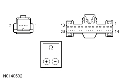 | Yes
INSTALL a new power liftgate motor. REFER to Power Liftgate Motor . TEST the system for normal operation. If the concern is still present, GO to I4 . No REPAIR the circuit in question. | ||||||||||||||||
| I4 CHECK FOR CORRECT LTM OPERATION | |||||||||||||||||
| Yes
CHECK On-Line Automotive Service Information System (OASIS) for any applicable TSBs . If a TSB exists for this concern, DISCONTINUE this test and FOLLOW TSB instructions. If no TSBs address this concern, INSTALL a new LTM . REFER to Liftgate/Trunk Module (LTM) . No The system is operating correctly at this time. The concern may have been caused by module connections. ADDRESS the root cause of any connector or pin issues. | ||||||||||||||||
Pinpoint Test J: DTC B117C
Diagnostics in this manual assume a certain skill level and knowledge of Ford-specific diagnostic practices. Refer to Diagnostic Methods in Section 100-00 for information about these practices.
Refer to Wiring Diagrams Cell 109 , Power Liftgate for schematic and connector information.
Refer to System Operation - Power Liftgate in Body Closures .
Refer to Component Description - Power Liftgate Latch in Body Closures .
LTM DTC Fault Trigger Conditions
| DTC | Description | Fault Trigger Conditions |
|---|---|---|
| B117C | Latch Centering Switch Invalid | Sets when the LTM detects the sector gear open/close switch(es) are not in the correct state at the beginning of self-test, or no sector gear switch transition during releasing/cinching. |
| Test Step | Result / Action to Take | ||||||||||||||||
|---|---|---|---|---|---|---|---|---|---|---|---|---|---|---|---|---|---|
| J1 RETRIEVE THE DTCs FROM THE LTM | |||||||||||||||||
| Yes
GO to J2 . No DIAGNOSE all other LTM DTCs first. REFER to the LTM DTC Chart in this section. | ||||||||||||||||
| J2 CHECK THE SECTOR GEAR SWITCH INPUT CIRCUITS FOR VOLTAGE | |||||||||||||||||
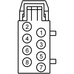 | Yes
INSTALL a new power liftgate latch. REFER to Section 501-14A . CLEAR the DTCs. REPEAT the LTM self-test. If DTC B117C returns, GO to J5 . No GO to J3 . | ||||||||||||||||
| J3 CHECK THE SECTOR GEAR SWITCH INPUT CIRCUITS FOR A SHORT TO GROUND | |||||||||||||||||
 | Yes
GO to J4 . No REPAIR the circuit in question. | ||||||||||||||||
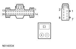
| J4 CHECK THE POWER LIFTGATE CHIME CIRCUITS FOR AN OPEN | |||||||||||||||||
 | Yes
INSTALL a new power liftgate latch. REFER to Section 501-14A . CLEAR the DTCs. REPEAT the LTM self-test. If DTC B117C returns, GO to J5 . No REPAIR the circuit in question. | ||||||||||||||||
| J5 CHECK FOR CORRECT LTM OPERATION | |||||||||||||||||
| Yes
CHECK On-Line Automotive Service Information System (OASIS) for any applicable TSBs . If a TSB exists for this concern, DISCONTINUE this test and FOLLOW TSB instructions. If no TSBs address this concern, INSTALL a new LTM . REFER to Liftgate/Trunk Module (LTM) . No The system is operating correctly at this time. The concern may have been caused by module connections. ADDRESS the root cause of any connector or pin issues. | ||||||||||||||||
Pinpoint Test K: DTC B2418, B2419 Or B2420
Diagnostics in this manual assume a certain skill level and knowledge of Ford-specific diagnostic practices. Refer to Diagnostic Methods in Section 100-00 for information about these practices.
Refer to Wiring Diagrams Cell 109 , Power Liftgate for schematic and connector information.
Refer to System Operation - Power Liftgate in Body Closures .
Refer to Component Description - Power Liftgate Motor in Body Closures .
LTM DTC Fault Trigger Conditions
| DTC | Description | Fault Trigger Conditions |
|---|---|---|
| B2418 | Sensor Power Short to Ground | Sets when the LTM detects less than 5 volts from the position sensor power circuit. |
| B2419 | Sensor 1 Invalid | Sets when the LTM detects the position sensor feedback signals are not correct. |
| B2420 | Sensor 2 Invalid | Sets when the LTM detects the position sensor feedback signals are not correct. |
| Test Step | Result / Action to Take | ||||||||||||||||
|---|---|---|---|---|---|---|---|---|---|---|---|---|---|---|---|---|---|
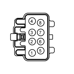
| K1 CHECK FOR VOLTAGE TO THE POSITION SENSOR | |||||||||||||||||
 | Yes
GO to K6 . No GO to K2 . | ||||||||||||||||
| K2 CHECK THE POSITION SENSOR VOLTAGE CIRCUIT | |||||||||||||||||
 | Yes
GO to K5 . No GO to K3 . | ||||||||||||||||
| K3 CHECK THE POSITION SENSOR VOLTAGE CIRCUIT FOR A SHORT TO GROUND | |||||||||||||||||
 | Yes
GO to K4 . No REPAIR the circuit. | ||||||||||||||||
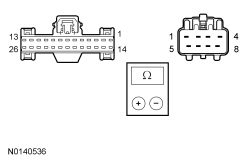
| K4 CHECK THE POSITION SENSOR VOLTAGE CIRCUIT FOR AN OPEN | |||||||||||||||||
 | Yes
GO to K10 . No REPAIR the circuit. | ||||||||||||||||
| K5 CHECK THE POSITION SENSOR RETURN CIRCUIT FOR AN OPEN | |||||||||||||||||
 | Yes
GO to K10 . No REPAIR the circuit. | ||||||||||||||||
| K6 CHECK THE POSITION SENSOR CIRCUITS FOR REFERENCE VOLTAGE | |||||||||||||||||
 | Yes
INSTALL a new power liftgate motor. REFER to Power Liftgate Motor . No GO to K7 . | ||||||||||||||||
| K7 CHECK THE POSITION SENSOR CIRCUITS FOR A SHORT TO VOLTAGE | |||||||||||||||||
 | Yes
REPAIR the circuit in question. No GO to K8 . | ||||||||||||||||
| K8 CHECK THE POSITION SENSOR CIRCUITS FOR A SHORT TO GROUND | |||||||||||||||||
 | Yes
GO to K9 . No REPAIR the circuit in question. | ||||||||||||||||
| K9 CHECK THE POSITION SENSOR CIRCUITS FOR AN OPEN | |||||||||||||||||
 | Yes
GO to K10 . No REPAIR the circuit in question. | ||||||||||||||||
| K10 CHECK FOR CORRECT LTM OPERATION | |||||||||||||||||
| Yes
CHECK On-Line Automotive Service Information System (OASIS) for any applicable TSBs . If a TSB exists for this concern, DISCONTINUE this test and FOLLOW TSB instructions. If no TSBs address this concern, INSTALL a new LTM . REFER to Liftgate/Trunk Module (LTM) . No The system is operating correctly at this time. The concern may have been caused by module connections. ADDRESS the root cause of any connector or pin issues. | ||||||||||||||||
Pinpoint Test L: DTC B2908
Diagnostics in this manual assume a certain skill level and knowledge of Ford-specific diagnostic practices. Refer to Diagnostic Methods in Section 100-00 for information about these practices.
Refer to Wiring Diagrams Cell 109 , Power Liftgate for schematic and connector information.
Refer to System Operation - Power Liftgate in Body Closures .
Refer to Component Description - Power Liftgate Latch in Body Closures .
LTM DTC Fault Trigger Conditions
| DTC | Description | Fault Trigger Conditions |
|---|---|---|
| B2908 | Latch Switch Invalid | Sets when the LTM detects the liftgate is not in the fully latched (primary) position at the beginning of self-test. This DTC may also set if the LTM does not detect a change in the latch status during latch releasing/cinching. |
| Test Step | Result / Action to Take | ||||||||||||||||||||||||||||||||||||||||||||||||||||
|---|---|---|---|---|---|---|---|---|---|---|---|---|---|---|---|---|---|---|---|---|---|---|---|---|---|---|---|---|---|---|---|---|---|---|---|---|---|---|---|---|---|---|---|---|---|---|---|---|---|---|---|---|---|
| L1 CHECK THE OPERATION OF THE DETENT AND FORKBOLT SWITCHES | |||||||||||||||||||||||||||||||||||||||||||||||||||||


| Yes
GO to L5 . No GO to L2 . | ||||||||||||||||||||||||||||||||||||||||||||||||||||
| L2 CHECK THE LIFTGATE LATCH GROUND CIRCUIT | |||||||||||||||||||||||||||||||||||||||||||||||||||||
 | Yes
GO to L3 . No REPAIR the circuit. | ||||||||||||||||||||||||||||||||||||||||||||||||||||
| L3 CHECK THE DETENT AND FORKBOLT SWITCH CIRCUITS FOR A SHORT TO GROUND | |||||||||||||||||||||||||||||||||||||||||||||||||||||
 | Yes
GO to L4 . No REPAIR the circuit in question. | ||||||||||||||||||||||||||||||||||||||||||||||||||||
| L4 CHECK THE DETENT AND FORKBOLT SWITCH CIRCUITS FOR AN OPEN | |||||||||||||||||||||||||||||||||||||||||||||||||||||
 | Yes
INSTALL a new liftgate latch. REFER to Section 501-14A . No REPAIR the circuit in question. | ||||||||||||||||||||||||||||||||||||||||||||||||||||
| L5 CHECK FOR CORRECT LTM OPERATION | |||||||||||||||||||||||||||||||||||||||||||||||||||||
| Yes
CHECK On-Line Automotive Service Information System (OASIS) for any applicable TSBs . If a TSB exists for this concern, DISCONTINUE this test and FOLLOW TSB instructions. If no TSBs address this concern, INSTALL a new LTM . REFER to Liftgate/Trunk Module (LTM) . No The system is operating correctly at this time. The concern may have been caused by module connections. ADDRESS the root cause of any connector or pin issues. | ||||||||||||||||||||||||||||||||||||||||||||||||||||
Pinpoint Test M: DTC B2935
Diagnostics in this manual assume a certain skill level and knowledge of Ford-specific diagnostic practices. Refer to Diagnostic Methods in Section 100-00 for information about these practices.
Refer to Wiring Diagrams Cell 109 , Power Liftgate for schematic and connector information.
Refer to System Operation - Power Liftgate in Body Closures .
Refer to Component Description - Power Liftgate Latch in Body Closures .
LTM DTC Fault Trigger Conditions
| DTC | Description | Fault Trigger Conditions |
|---|---|---|
| B2935 | Drive Unit Failure | Sets when the LTM self-test cycle (power open and power close to fully latched position) exceeds 20 seconds. |
| Test Step | Result / Action to Take |
|---|---|
| M1 RETRIEVE THE DTCs FROM THE LTM | |
| Yes
GO to M2 . No DIAGNOSE all other LTM DTCs first. REFER to the LTM DTC Chart in this section. |
| M2 CHECK THE MANUAL RELEASE OPERATION OF THE LIFTGATE LATCH | |
| Yes
GO to M3 . No INSTALL a new power liftgate latch. REFER to Section 501-14A . |
| M3 CHECK THE MANUAL OPERATION OF THE LIFTGATE | |
| Yes
INSTALL a new power liftgate motor. REFER to Power Liftgate Motor . No REPAIR and ALIGN as necessary. REFER to Liftgate Alignment . |
Pinpoint Test N: DTC B1317
Diagnostics in this manual assume a certain skill level and knowledge of Ford-specific diagnostic practices. Refer to Diagnostic Methods in Section 100-00 for information about these practices.
The LTM constantly monitors the voltage supply circuit. If the voltage exceeds a set parameter, the LTM sets a DTC.
LTM DTC Fault Trigger Conditions
| DTC | Description | Fault Trigger Conditions |
|---|---|---|
| B1317 | Battery Voltage High | Sets when the LTM detects battery voltage above 16 volts from the voltage supply circuits. Power liftgate operation is inhibited when this DTC sets. |
NOTE: DTC B1317 may be stored in the module memory due to previous battery charging or vehicle jump starting events.
| Test Step | Result / Action to Take |
|---|---|
| N1 CHECK FOR CHARGING SYSTEM DTCs SET IN OTHER MODULES | |
| Yes
REFER to Section 414-00 to diagnose an overcharging condition. No GO to N2 . |
| N2 CHECK THE BATTERY VOLTAGE | |
| Yes
REFER to Section 414-00 to diagnose an overcharging condition. No GO to N3 . |
| N3 RECHECK FOR DTC B1317 | |
| Yes
INSTALL a new LTM . REFER to Liftgate/Trunk Module (LTM) . No The system is operating normally at this time. The DTC may have been set previously during battery charging or while jump starting the vehicle. |
Pinpoint Test O: DTC B1318
Diagnostics in this manual assume a certain skill level and knowledge of Ford-specific diagnostic practices. Refer to Diagnostic Methods in Section 100-00 for information about these practices.
Refer to Wiring Diagrams Cell 109 , Power Liftgate for schematic and connector information.
The LTM constantly monitors the voltage supply circuit. If the voltage exceeds a set parameter, the LTM sets a DTC.
LTM DTC Fault Trigger Conditions
| DTC | Description | Fault Trigger Conditions |
|---|---|---|
| B1318 | Battery Voltage Low | Sets when the LTM detects battery voltage below 8 volts from the power supply circuits. Power liftgate operation is inhibited when this DTC sets. |
| Test Step | Result / Action to Take | ||||||||||||||||
|---|---|---|---|---|---|---|---|---|---|---|---|---|---|---|---|---|---|
| O1 RECHECK THE LTM DTCs | |||||||||||||||||
| Yes
GO to O2 . No The system is operating normally at this time. The DTC may have been set due to a previous low battery voltage condition. | ||||||||||||||||
| O2 CHECK FOR CHARGING SYSTEM DTCs IN THE PCM | |||||||||||||||||
| Yes
REFER to Section 414-00 . No GO to O3 . | ||||||||||||||||
| O3 CHECK THE BATTERY CONDITION AND STATE OF CHARGE | |||||||||||||||||
| Yes
GO to O4 . No REFER to Section 414-01 . | ||||||||||||||||
| O4 CHECK THE LTM VOLTAGE PIDs | |||||||||||||||||
| Yes
GO to O7 . No GO to O5 . | ||||||||||||||||
| O5 CHECK THE LTM VOLTAGE SUPPLY CIRCUITS FOR HIGH RESISTANCE | |||||||||||||||||
 | Yes
GO to O6 . No REPAIR the circuit in question. | ||||||||||||||||
| O6 CHECK THE LTM GROUND CIRCUIT FOR HIGH RESISTANCE | |||||||||||||||||
 | Yes
GO to O7 . No REPAIR the circuit. | ||||||||||||||||
| O7 CHECK FOR CORRECT LTM OPERATION | |||||||||||||||||
| Yes
CHECK On-Line Automotive Service Information System (OASIS) for any applicable TSBs . If a TSB exists for this concern, DISCONTINUE this test and FOLLOW TSB instructions. If no TSBs address this concern, INSTALL a new LTM . REFER to Liftgate/Trunk Module (LTM) . No The system is operating correctly at this time. The concern may have been caused by module connections. ADDRESS the root cause of any connector or pin issues. | ||||||||||||||||
Pinpoint Test P: DTC U0140
Diagnostics in this manual assume a certain skill level and knowledge of Ford-specific diagnostic practices. Refer to Diagnostic Methods in Section 100-00 for information about these practices.
The LTM and the BCM communicate using the MS-CAN . Messages are exchanged between the modules on the MS-CAN for the purposes of determining what functions are being carried out.
LTM DTC Fault Trigger Conditions
| DTC | Description | Fault Trigger Conditions |
|---|---|---|
| U0140 | Lost Communication With Body Control Module (GEM) | Sets by the LTM if data messages received from the BCM over the MS-CAN are missing. |
| Test Step | Result / Action to Take |
|---|---|
| P1 VERIFY CUSTOMER CONCERN | |
| Yes
GO to P2 . No The system is operating normally at this time. The DTC may have been set due to high network traffic or intermittent fault condition. |
| P2 CHECK THE COMMUNICATION NETWORK | |
| Yes
GO to P3 . No REFER to Section 418-00 , The Body Control Module (BCM) Does Not Respond To The Scan Tool. |
| P3 RETRIEVE THE RECORDED DTCs FROM THE BCM SELF-TEST | |
| Yes
REFER to Section 419-10 . No GO to P4 . |
| P4 RETRIEVE THE RECORDED DTCs FROM THE LTM SELF-TEST | |
| Yes
For DTC B1317, GO to Pinpoint Test N . For DTC B1318, GO to Pinpoint Test O . No GO to P5 . |
| P5 RECHECK THE LTM DTCs | |
NOTE: If new modules were installed prior to the DTC being set, the module configuration may be incorrectly set during PMI or the PMI may not have been carried out. | Yes
GO to P6 . No The system is operating correctly at this time. The DTC may have been set due to high network traffic or intermittent fault condition. |
| P6 CHECK FOR DTC U0140 IN OTHER MODULES | |
| Yes
INSTALL a new BCM . REFER to Section 419-10 . No INSTALL a new LTM . REFER to Liftgate/Trunk Module (LTM) . |
Pinpoint Test Q: DTC U0155
Diagnostics in this manual assume a certain skill level and knowledge of Ford-specific diagnostic practices. Refer to Diagnostic Methods in Section 100-00 for information about these practices.
The LTM and the IPC communicate using the MS-CAN . Messages are exchanged between the modules on the MS-CAN for the purposes of determining what functions are being carried out.
LTM DTC Fault Trigger Conditions
| DTC | Description | Fault Trigger Conditions |
|---|---|---|
| U0155 | Lost Communication With Instrument Panel Cluster (IC) Control Module | Sets by the LTM if data messages received from the IPC over the MS-CAN are missing. |
| Test Step | Result / Action to Take |
|---|---|
| Q1 VERIFY CUSTOMER CONCERN | |
| Yes
GO to Q2 . No The system is operating normally at this time. The DTC may have been set due to high network traffic or intermittent fault condition. |
| Q2 CHECK THE COMMUNICATION NETWORK | |
| Yes
GO to Q3 . No REFER to Section 418-00 , The Instrument Panel Cluster (IPC) Does Not Respond To The Scan Tool. |
| Q3 RETRIEVE THE RECORDED DTCs FROM THE IPC SELF-TEST | |
| Yes
REFER to Section 413-01 . No GO to Q4 . |
| Q4 RETRIEVE THE RECORDED DTCs FROM THE LTM SELF-TEST | |
| Yes
For DTC B1317, GO to Pinpoint Test N . For DTC B1318, GO to Pinpoint Test O . No GO to Q5 . |
| Q5 RECHECK THE LTM DTCs | |
NOTE: If new modules were installed prior to the DTC being set, the module configuration may be incorrectly set during PMI or the PMI may not have been carried out. | Yes
GO to Q6 . No The system is operating correctly at this time. The DTC may have been set due to high network traffic or intermittent fault condition. |
| Q6 CHECK FOR DTC U0155 IN OTHER MODULES | |
| Yes
INSTALL a new IPC . REFER to Section 413-01 . No INSTALL a new LTM . REFER to Liftgate/Trunk Module (LTM) . |