
SGT27000

NUD105-R025D
SECTION 501-14B: Handles, Locks, Latches and Entry Systems — With Intelligent Access (IA)
| 2014 Flex Workshop Manual
|
DIAGNOSIS AND TESTING
| Procedure revision date: 05/02/2013
|
 | Circuit Tester/Test Light
SGT27000 |
 | Flex Probe Kit
NUD105-R025D |
| Item | Specification |
|---|---|
| Motorcraft® Penetrating and Lock Lubricant (US); Motorcraft® Penetrating Fluid (Canada)
XL-1 (US); CXC-51-A (Canada) | — |
| Motorcraft® Multi-Purpose Grease
XL-5 | ESB-M1C93-B |
DTC Charts
Diagnostics in this manual assume a certain skill level and knowledge of Ford-specific diagnostic practices. Refer to Diagnostic Methods in Section 100-00 for information about these practices.
DDM DTC Chart
| DTC | Description | Action |
|---|---|---|
| B106E | Solid State Driver Disabled Due to Short Circuit | GO to Pinpoint Test S . |
| B106F | Module Disabled Due to External Fault | GO to Pinpoint Test S . |
| B1317 | Battery Voltage High | GO to Pinpoint Test T . |
| B1318 | Battery Voltage Low | GO to Pinpoint Test U . |
| B1342 | ECU Is Faulted | DIAGNOSE all other DTCs first. CLEAR the DTCs and REPEAT the self-test. If DTC B1342 is retrieved again, INSTALL a new DDM . REFER to Driver Door Module (DDM) . |
| B1534 | Memory 1 Switch Circuit Short To Ground | REFER to Section 501-10 . |
| B1538 | Memory 2 Switch Circuit Short To Ground | REFER to Section 501-10 . |
| B1667 | Mirror Driver Up/Down Motor Stalled | REFER to Section 501-09 . |
| B1668 | Mirror Driver Right/Left Motor Stalled | REFER to Section 501-09 . |
| B1733 | Mirror Driver Vertical Switch Circuit Failure | REFER to Section 501-09 . |
| B1737 | Mirror Driver Horizontal Switch Circuit Failure | REFER to Section 501-09 . |
| B1741 | Mirror Passenger Vertical Switch Circuit Failure | REFER to Section 501-09 . |
| B1745 | Mirror Passenger Horizontal Switch Circuit Failure | REFER to Section 501-09 . |
| B2223 | Mirror Driver Drive Circuit Failure | REFER to Section 501-09 . |
| B2320 | Mirror Driver Horizontal Feedback Potentiometer Circuit Failure | REFER to Section 501-09 . |
| B2322 | Mirror Driver Horizontal Feedback Potentiometer Circuit Short to Battery | REFER to Section 501-09 . |
| B2324 | Mirror Driver Vertical Feedback Potentiometer Circuit Failure | REFER to Section 501-09 . |
| B2326 | Mirror Driver Vertical Feedback Potentiometer Circuit Short to Battery | REFER to Section 501-09 . |
| B2477 | Module Configuration Failure | Using a scan tool, CARRY OUT the PMI using As-Built data. |
| B2574 | Drivers Door Lock Switch Short to Ground | GO to Pinpoint Test J . |
| B2575 | Drivers Door Unlock Switch Short to Ground | GO to Pinpoint Test J . |
| U0140 | Lost Communication With Body Control Module (GEM) | GO to Pinpoint Test V . |
| U2050 | No Application Present | Using a scan tool, CARRY OUT the PMI using As-Built data. |
BCM DTC Chart
| DTC | Description | Action |
|---|---|---|
| B126A:01 | Drivers Door Interior Lock Switch: General Electrical Failure | GO to Pinpoint Test J . |
| All other DTCs | — | REFER to the BCM DTC Chart in Section 419-10 . |
RFA Module DTC Chart
| DTC | Description | Action |
|---|---|---|
| B10AB:06 | Remote Keyless Entry Synchronization: Algorithm Based Failures | GO to Pinpoint Test N . |
| B10C6:01 | Exterior Trunk Antenna: General Electrical Failure | GO to Pinpoint Test R . |
| B10D7:31 | PATS Key: No Signal | This DTC sets during the RFA module self-test if 2 programmed Intelligent Access (IA) keys are not detected inside the vehicle. CHECK each Intelligent Access (IA) key individually to see if it operates the vehicle. If 2 programmed Intelligent Access (IA) keys are not present inside the vehicle, DISREGARD this DTC |
| B113E:11 | External Boot/Trunk Release Switch: Circuit Short To Ground | REFER to Section 501-03 . |
| B11C6:01 | Passenger Door External Antenna: General Electrical Failure | GO to Pinpoint Test Q . |
| B11CA:01 | Driver Door External Antenna: General Electrical Failure | GO to Pinpoint Test Q . |
| B1219:11 | Interior Boot/Trunk Release Switch: Circuit Short To Ground | GO to Pinpoint Test R . |
| B121A:11 | Keypad Illumination Output: Circuit Short To Ground | GO to Pinpoint Test M . |
| B121A:15 | Keypad Illumination Output: Circuit Short To Battery Or Open | GO to Pinpoint Test M . |
| B121B:11 | Keypad Input Switch: Circuit Short To Ground | GO to Pinpoint Test L . |
| B1381:11 | Left Front Door Handle Proximity Sensor: Circuit Short To Ground | GO to Pinpoint Test Q . |
| B1381:15 | Left Front Door Handle Proximity Sensor: Circuit Short To Battery or Open | GO to Pinpoint Test Q . |
| B1381:29 | Left Front Door Handle Proximity Sensor: Signal Invalid | CLEAR the DTCs. REPEAT the self-test. If DTC B1381:29 returns, INSTALL a new left front exterior door handle. REFER to Exterior Door Handle . |
| B1382:11 | Right Front Door Handle Proximity Sensor: Circuit Short To Ground | GO to Pinpoint Test Q . |
| B1382:15 | Right Front Door Handle Proximity Sensor: Circuit Short To Battery or Open | GO to Pinpoint Test Q . |
| B1382:29 | Right Front Door Handle Proximity Sensor: Signal Invalid | CLEAR the DTCs. REPEAT the self-test. If DTC B1382:29 returns, INSTALL a new right front exterior door handle. REFER to Exterior Door Handle . |
| U201F:31 | External Receiver: No Signal | GO to Pinpoint Test N . |
| All other DTCs | — | REFER to the RFA Module DTC Chart in Section 419-10 . |
Symptom Charts
Diagnostics in this manual assume a certain skill level and knowledge of Ford-specific diagnostic practices. Refer to Diagnostic Methods in Section 100-00 for information about these practices.
| Condition | Possible Sources | Action |
|---|---|---|
|
| |
|
| |
|
| |
|
| |
|
| |
|
|
|
|
| |
|
|
| Condition | Possible Sources | Action |
|---|---|---|
|
| |
|
| |
|
| |
|
| |
|
|
|
|
| |
|
| |
|
| |
|
| |
|
| |
|
|
|
|
|
|
|
| |
|
|
Pinpoint Tests
Pinpoint Test A: Hard To Open Or Close Door From Either Door Handle
Diagnostics in this manual assume a certain skill level and knowledge of Ford-specific diagnostic practices. Refer to Diagnostic Methods in Section 100-00 for information about these practices.
The door latch can be actuated from the interior or exterior door handle. When actuated, the door latch releases and allows the door to open. If the door latch or the door hinges have insufficient lubrication or if the striker or door are misaligned, it causes extra force to be used when opening or closing the door.
| Test Step | Result / Action to Take |
|---|---|
| A1 CHECK THE LATCH OPERATION FROM BOTH DOOR HANDLES | |
| Yes
If the door is difficult/does not open from the exterior door handle, GO to Pinpoint Test B . If the door is difficult/does not open from the interior door handle, GO to Pinpoint Test C . No If the door is difficult/does not open from both door handles, GO to A2 . |
| A2 CHECK THE LATCH OPERATION | |
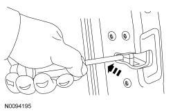 | Yes
GO to A4 . No GO to A3 . |
| A3 CHECK THE LATCH OPERATION AFTER LUBRICATION | |
 | Yes
The concern was caused by an insufficiently lubricated door latch. No INSTALL a new door latch. REFER to Front Door Latch or Rear Door Latch . |
| A4 CHECK THE STRIKER ADJUSTMENT | |
| Yes
GO to A5 . No ADJUST the striker as necessary. |
| A5 CHECK THE DOOR ALIGNMENT | |
| Yes
LUBRICATE the door hinges. No ADJUST the door as necessary. |
Pinpoint Test B: A Door Is Difficult Or Does Not Open From The Exterior Door Handle
Diagnostics in this manual assume a certain skill level and knowledge of Ford-specific diagnostic practices. Refer to Diagnostic Methods in Section 100-00 for information about these practices.
The exterior door handle is connected to the door latch with an actuating rod. When the exterior door handle is pulled, the actuating rod pushes down on the latch lever. When the latch lever is moved, the door latch releases, allowing the door to open.
| Test Step | Result / Action to Take |
|---|---|
| B1 CHECK THE LATCH OPERATION FROM BOTH DOOR HANDLES | |
| Yes
GO to Pinpoint Test A . No GO to B2 . |
| B2 CHECK THE EXTERIOR DOOR HANDLE REINFORCEMENT | |
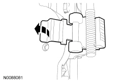 | Yes
GO to B3 . No INSTALL a new exterior door handle reinforcement. REFER to Door Handle Reinforcement — Exterior, Front or Door Handle Reinforcement — Exterior, Rear . |
| B3 CHECK THE EXTERIOR DOOR HANDLE AND LINKAGE OPERATION | |
| Yes
REPAIR as necessary. No INSTALL a new door latch. REFER to Front Door Latch or Rear Door Latch . |
Pinpoint Test C: A Door Is Difficult Or Does Not Open From The Interior Door Handle
Diagnostics in this manual assume a certain skill level and knowledge of Ford-specific diagnostic practices. Refer to Diagnostic Methods in Section 100-00 for information about these practices.
The interior door handle is connected to the door latch by an actuating cable. When the interior door handle is pulled, the cable pulls on the latch lever. When the latch lever is moved, the door latch releases, allowing the door to open.
Visual Inspection and Diagnostic Pre-checks
| Test Step | Result / Action to Take |
|---|---|
| C1 CHECK THE LATCH OPERATION FROM BOTH DOOR HANDLES | |
| Yes
GO to Pinpoint Test A . No GO to C2 . |
| C2 CHECK THE INTERIOR DOOR HANDLE AND CABLE/LINKAGE OPERATION | |
| Yes
REPAIR as necessary. No INSTALL a new door latch. REFER to Front Door Latch or Rear Door Latch . |
Pinpoint Test D: The Exterior Door Release Handle Sticks
Diagnostics in this manual assume a certain skill level and knowledge of Ford-specific diagnostic practices. Refer to Diagnostic Methods in Section 100-00 for information about these practices.
The exterior door handle is connected to the door latch with an actuating rod. When the exterior door handle is pulled, the actuating rod pushes down on the latch lever. When the latch lever is moved, the door latch releases, allowing the door to open. The handle has a return spring to make sure the handle returns to a closed position.
| Test Step | Result / Action to Take |
|---|---|
| D1 CHECK FOR A BROKEN RETURN SPRING | |
 | Yes
GO to D2 . No INSTALL a new exterior door handle reinforcement. REFER to Door Handle Reinforcement — Exterior, Front or Door Handle Reinforcement — Exterior, Rear . |
| D2 CHECK THE EXTERIOR DOOR HANDLE AND LINKAGE OPERATION | |
| Yes
REPAIR as necessary No INSTALL a new door latch. REFER to Front Door Latch or Rear Door Latch . |
Pinpoint Test E: The Interior Door Release Handle Sticks
Diagnostics in this manual assume a certain skill level and knowledge of Ford-specific diagnostic practices. Refer to Diagnostic Methods in Section 100-00 for information about these practices.
The interior door handle is connected to the door latch by an actuating cable. When the interior door handle is pulled, the cable pulls on the latch lever. When the latch lever is moved, the door latch releases, allowing the door to open. The handle has a return spring to make sure the handle returns to a closed position.
| Test Step | Result / Action to Take |
|---|---|
| E1 CHECK FOR A BROKEN RETURN SPRING | |
| Yes
GO to E2 . No INSTALL a new interior door handle. REFER to Interior Door Handle . |
| E2 CHECK THE INTERIOR DOOR HANDLE CABLE OPERATION | |
| Yes
INSTALL a new door latch. REFER to Front Door Latch or Rear Door Latch . No REPAIR as necessary. |
Pinpoint Test F: Squeak-Rattle-Chucking Noise From Door
Diagnostics in this manual assume a certain skill level and knowledge of Ford-specific diagnostic practices. Refer to Diagnostic Methods in Section 100-00 for information about these practices.
| Test Step | Result / Action to Take |
|---|---|
| F1 CHECK FOR ANY LOOSE COMPONENTS | |
| Yes
REPAIR as necessary. No GO to F2 . |
| F2 CHECK THE STRIKER ADJUSTMENT | |
| Yes
GO to F3 . No ADJUST the striker as necessary. |
| F3 CHECK THE DOOR ALIGNMENT | |
| Yes
GO to F4 . No ADJUST the door as necessary. |
| F4 CHECK THE LATCH OPERATION AFTER LUBRICATION | |
 | Yes
INSTALL a new door latch. REFER to Front Door Latch or Rear Door Latch . No The concern was caused by an insufficiently lubricated door latch. |
Pinpoint Test G: The Manual Door Lock Cylinder Is Inoperative
Diagnostics in this manual assume a certain skill level and knowledge of Ford-specific diagnostic practices. Refer to Diagnostic Methods in Section 100-00 for information about these practices.
The door lock cylinder is connected to the door latch via a lock rod and can be used to manually lock/unlock the door.
| Test Step | Result / Action to Take |
|---|---|
| G1 CHECK THE LOCK CYLINDER OPERATION AFTER LUBRICATION | |
| Yes
The concern was caused by an insufficiently lubricated lock cylinder. SPRAY a multi-purpose grease such as Motorcraft XL-5 into the lock cylinder for a couple seconds to provide long term lubrication. No GO to G2 . |
| G2 CHECK THE DOOR LOCK CYLINDER | |
| Yes
GO to G3 . No INSTALL a new door lock cylinder. REFER to Door Lock Cylinder . |
| G3 CHECK THE DOOR LOCK CYLINDER LINKAGE | |
| Yes
REPAIR as necessary. No INSTALL a new door latch. REFER to Front Door Latch . |
Pinpoint Test H: All Door Locks Are Inoperative
Diagnostics in this manual assume a certain skill level and knowledge of Ford-specific diagnostic practices. Refer to Diagnostic Methods in Section 100-00 for information about these practices.
Refer to Wiring Diagrams Cell 117 , Remote Keyless Entry and Alarm for schematic and connector information.
Refer to System Operation, Power Door Locks in Handles, Locks, Latches and Entry Systems .
Visual Inspection and Diagnostic Pre-checks
| Test Step | Result / Action to Take |
|---|---|
| H1 PERFORM THE BCM SELF-TEST | |
| Yes
GO to Pinpoint Test J . No GO to H2 . |
| H2 CHECK THE RECORDED DTCs FROM THE DDM SELF-TEST | |
| Yes
GO to Pinpoint Test J . No GO to H3 . |
| H3 VERIFY THE OPERATION OF BOTH DOOR LOCK CONTROL SWITCHES | |
| Yes
GO to H4 . No GO to Pinpoint Test K . |
| H4 VERIFY ALL DOOR LOCKS ARE INOPERATIVE | |
| Yes
GO to H5 . No GO to Pinpoint Test I . |
| H5 CHECK THE RFA MODULE POWER DOOR LOCK RELAY CIRCUIT FOR VOLTAGE | |
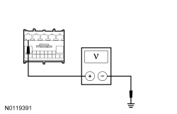 | Yes
GO to H8 . No VERIFY the BCM fuse 27 (20A) is OK. If OK, GO to H6 . If not OK, GO to H7 . |
| H6 CHECK THE RFA MODULE DOOR LOCK RELAY VOLTAGE SUPPLY CIRCUIT FOR AN OPEN | |
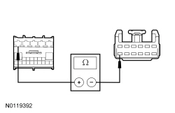 | Yes
GO to H10 . No REPAIR the circuit. |
| H7 CHECK THE ALL LOCK CIRCUIT FOR A SHORT TO GROUND | |
NOTE: If the BCM fuse 27 (20A) fails immediately upon installation, refer to the Wiring Diagrams manual to identify the possible causes of the circuit short. | Yes
REPAIR the unlock circuit for a short to ground. No REPAIR the all lock circuit for a short to ground. |
| H8 CHECK THE RFA MODULE POWER DOOR LOCK RELAY GROUND CIRCUIT FOR AN OPEN | |
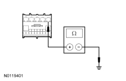 | Yes
GO to H9 . No REPAIR the circuit. |
| H9 CHECK THE ALL DOOR LOCK CIRCUIT FOR AN OPEN | |
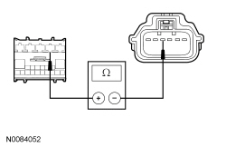 | Yes
GO to H11 . No REPAIR the circuit. |
| H10 CHECK FOR CORRECT BCM OPERATION | |
| Yes
CHECK On-Line Automotive Service Information System (OASIS) for any applicable TSBs . If a TSB exists for this concern, DISCONTINUE this test and FOLLOW TSB instructions. If no TSBs address this concern, INSTALL a new BCM . REFER to Section 419-10 . No The system is operating correctly at this time. The concern may have been caused by module connections. ADDRESS the root cause of any connector or pin issues. |
| H11 CHECK FOR CORRECT RFA MODULE OPERATION | |
| Yes
CHECK On-Line Automotive Service Information System (OASIS) for any applicable TSBs . If a TSB exists for this concern, DISCONTINUE this test and FOLLOW TSB instructions. If no TSBs address this concern, INSTALL a new RFA module. REFER to Section 419-10 . No The system is operating correctly at this time. The concern may have been caused by module connections. ADDRESS the root cause of any connector or pin issues. |
Pinpoint Test I: A Single Or More Than One Door Lock Is Inoperative
Diagnostics in this manual assume a certain skill level and knowledge of Ford-specific diagnostic practices. Refer to Diagnostic Methods in Section 100-00 for information about these practices.
Refer to Wiring Diagrams Cell 117 , Remote Keyless Entry and Alarm for schematic and connector information.
Refer to System Operation, Power Door Locks in Handles, Locks, Latches and Entry Systems .
Visual Inspection and Diagnostic Pre-checks
| Test Step | Result / Action to Take | |||||||||||||||
|---|---|---|---|---|---|---|---|---|---|---|---|---|---|---|---|---|
| I1 CHECK THE MECHANICAL ACTION OR THE DOOR LOCK ROD | ||||||||||||||||
| Yes
GO to I3 . No GO to I2 . | |||||||||||||||
| I2 CHECK THE LOCK ROD FOR BINDING | ||||||||||||||||
| Yes
REPAIR as necessary. No INSTALL a new door latch. REFER to Front Door Latch or Rear Door Latch . | |||||||||||||||
| I3 CHECK THE ALL LOCK OUTPUT CIRCUIT FOR AN OPEN | ||||||||||||||||
NOTICE: This test step uses a test light to simulate normal circuit loads. Use only the test lamp recommended in the Special Tools table (or electrical equivalent) at the beginning of this section. To avoid connector terminal damage, use the Rotunda Flex Probe kit for the test light probe connection to the vehicle. Do not use the test light probe directly on any connector.
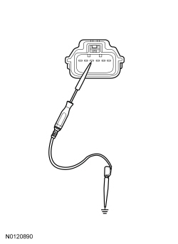 | Yes
GO to I4 . No REPAIR the circuit. | |||||||||||||||
| I4 CHECK THE UNLOCK OUTPUT CIRCUIT FOR VOLTAGE | ||||||||||||||||
NOTICE: This test step uses a test light to simulate normal circuit loads. Use only the test light recommended in the Special Tools table (or electrical equivalent) at the beginning of this section. To avoid connector terminal damage, use the Rotunda Flex Probe kit for the test light probe connection to the vehicle. Do not use the test light probe directly on any connector.
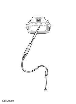 | Yes
INSTALL a new door latch. REFER to Front Door Latch or Rear Door Latch . No GO to I5 . | |||||||||||||||
| I5 CHECK THE UNLOCK OUTPUT CIRCUIT FOR AN OPEN | ||||||||||||||||
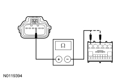 | Yes
GO to I6 . No REPAIR the circuit in question. | |||||||||||||||
| I6 CHECK FOR CORRECT RFA MODULE OPERATION | ||||||||||||||||
| Yes
CHECK On-Line Automotive Service Information System (OASIS) for any applicable TSBs . If a TSB exists for this concern, DISCONTINUE this test and FOLLOW TSB instructions. If no TSBs address this concern, INSTALL a new RFA module. REFER to Section 419-10 . No The system is operating correctly at this time. The concern may have been caused by module connections. ADDRESS the root cause of any connector or pin issues. |
Pinpoint Test J: The Door Locks Operate Only One Way
Diagnostics in this manual assume a certain skill level and knowledge of Ford-specific diagnostic practices. Refer to Diagnostic Methods in Section 100-00 for information about these practices.
Refer to Wiring Diagrams Cell 117 , Remote Keyless Entry and Alarm for schematic and connector information.
Refer to System Operation, Power Door Locks in Handles, Locks, Latches and Entry Systems .
Refer to Component Description, Door Lock Control Switch in Handles, Locks, Latches and Entry Systems .
BCM DTC Fault Trigger Conditions
| DTC | Description | Fault Trigger Conditions |
|---|---|---|
| Drivers Door Interior Lock Switch: General Electrical Failure | Sets when the BCM detects a short to ground from the right door lock control switch lock or unlock request input circuits. |
DDM DTC Fault Trigger Conditions
| DTC | Description | Fault Trigger Conditions |
|---|---|---|
| Drivers Door Lock Switch Short to Ground | Sets when the DDM detects a short to ground from the left door lock control switch lock request input circuit. |
| Drivers Door Unlock Switch Short to Ground | Sets when the DDM detects a short to ground from the left door lock control switch unlock request input circuit. |
Visual Inspection and Diagnostic Pre-checks
| Test Step | Result / Action to Take |
|---|---|
| J1 CHECK THE RECORDED BCM DTCs FROM THE SELF-TEST | |
| Yes
GO to J2 . No GO to J4 . |
| J2 CHECK THE RIGHT DOOR LOCK CONTROL SWITCH | |
| Yes
GO to J3 . No INSTALL a new door lock control switch. REFER to Door Lock Control Switch . |
| J3 CHECK THE LOCK OR THE UNLOCK INPUT CIRCUIT FOR A SHORT TO GROUND (RIGHT SWITCH) | |
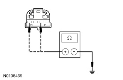 | Yes
GO to J12 . No REPAIR the circuit in question. |
| J4 CHECK THE RECORDED DDM DTCs FROM THE SELF-TEST | |
| Yes
GO to J5 . No For a concern with the left door lock control switch, GO to J7 . For a concern with the right door lock control switch, GO to J9 . |
| J5 CHECK THE LEFT DOOR LOCK CONTROL SWITCH | |
| Yes
GO to J6 . No INSTALL a new door lock control switch. REFER to Door Lock Control Switch . |
| J6 CHECK THE LOCK OR THE UNLOCK INPUT CIRCUIT FOR A SHORT TO GROUND (LEFT SWITCH) | |
 | Yes
GO to J11 . No REPAIR the circuit in question. |
| J7 BYPASS THE LEFT DOOR LOCK CONTROL SWITCH | |
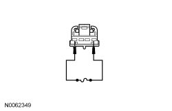 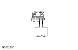 | Yes
INSTALL a new door lock control switch. REFER to Door Lock Control Switch . No GO to J8 . |
| J8 CHECK THE LEFT DOOR LOCK CONTROL SWITCH INPUT CIRCUITS FOR AN OPEN | |
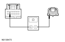 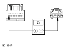 | Yes
GO to J11 . No REPAIR the circuit in question. |
| J9 BYPASS THE RIGHT DOOR LOCK CONTROL SWITCH | |
  | Yes
INSTALL a new door lock control switch. REFER to Door Lock Control Switch . No GO to J10 . |
| J10 CHECK THE RIGHT DOOR LOCK CONTROL SWITCH INPUT CIRCUITS FOR AN OPEN | |
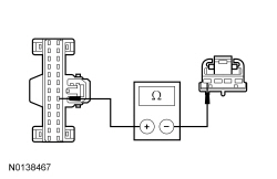 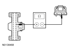 | Yes
GO to J12 . No REPAIR the circuit in question. |
| J11 CHECK FOR CORRECT DDM OPERATION | |
| Yes
CHECK On-Line Automotive Service Information System (OASIS) for any applicable TSBs . If a TSB exists for this concern, DISCONTINUE this test and FOLLOW TSB instructions. If no TSBs address this concern, INSTALL a new DDM . REFER to Driver Door Module (DDM) . No The system is operating correctly at this time. The concern may have been caused by module connections. ADDRESS the root cause of any connector or pin issues. |
| J12 CHECK FOR CORRECT BCM OPERATION | |
| Yes
CHECK On-Line Automotive Service Information System (OASIS) for any applicable TSBs . If a TSB exists for this concern, DISCONTINUE this test and FOLLOW TSB instructions. If no TSBs address this concern, INSTALL a new BCM . REFER to Section 419-10 . No The system is operating correctly at this time. The concern may have been caused by module connections. ADDRESS the root cause of any connector or pin issues. |
Pinpoint Test K: All Door Locks Are Inoperative From One Switch
Diagnostics in this manual assume a certain skill level and knowledge of Ford-specific diagnostic practices. Refer to Diagnostic Methods in Section 100-00 for information about these practices.
Refer to Wiring Diagrams Cell 117 , Remote Keyless Entry and Alarm for schematic and connector information.
Refer to System Operation, Power Door Locks in Handles, Locks, Latches and Entry Systems .
Refer to Component Description, Door Lock Control Switch in Handles, Locks, Latches and Entry Systems .
Visual Inspection and Diagnostic Pre-checks
| Test Step | Result / Action to Take |
|---|---|
| K1 CHECK FOR NETWORK COMMUNICATION TO THE DDM , BCM AND THE RFA MODULE | |
| Yes
GO to K2 . No REFER to Section 418-00 to diagnose the suspect module not responding to the scan tool. |
| K2 CHECK THE DOOR LOCK CONTROL SWITCH GROUND CIRCUIT FOR AN OPEN | |
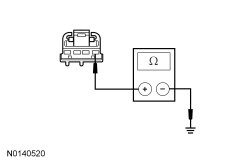 | Yes
INSTALL a new door lock control switch. REFER to Door Lock Control Switch . No REPAIR the circuit. |
Pinpoint Test L: The Doors Do Not Lock Or Unlock Using The Keyless Entry Keypad
Diagnostics in this manual assume a certain skill level and knowledge of Ford-specific diagnostic practices. Refer to Diagnostic Methods in Section 100-00 for information about these practices.
Refer to Wiring Diagrams Cell 117 , Remote Keyless Entry and Alarm for schematic and connector information.
Refer to System Operation, Keyless Entry Keypad in Handles, Locks, Latches and Entry Systems .
Refer to Component Description, Keyless Entry Keypad in Handles, Locks, Latches and Entry Systems .
RFA Module DTC Fault Trigger Conditions
| DTC | Description | Fault Trigger Conditions |
|---|---|---|
| Keypad Input Switch: Circuit Short to Ground | Sets when the RFA module detects a short to ground from any of the keyless entry keypad input circuits. |
Visual Inspection and Diagnostic Pre-checks
| Test Step | Result / Action to Take | ||||||||||||
|---|---|---|---|---|---|---|---|---|---|---|---|---|---|
| L1 CHECK POWER LOCK OPERATION FROM THE DOOR LOCK CONTROL SWITCH | |||||||||||||
| Yes
GO to L2 . No GO to Pinpoint Test H . | ||||||||||||
| L2 CHECK THE KEYLESS ENTRY KEYPAD ILLUMINATION | |||||||||||||
| Yes
GO to L7 . No GO to L3 . | ||||||||||||
| L3 CHECK THE KEYLESS ENTRY KEYPAD INDICATOR | |||||||||||||
| Yes
GO to Pinpoint Test M . No GO to L4 . | ||||||||||||
| L4 CHECK FOR VOLTAGE TO THE KEYLESS ENTRY KEYPAD | |||||||||||||
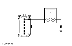 | Yes
GO to L6 . No VERIFY the BCM fuse 7 (7.5A) is OK. If OK, GO to L5 . If not OK, REFER to the Wiring Diagrams manual to identify the possible causes of the circuit short. | ||||||||||||
| L5 CHECK THE KEYLESS ENTRY KEYPAD VOLTAGE SUPPLY CIRCUIT FOR AN OPEN | |||||||||||||
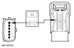 | Yes
GO to L16 . No REPAIR the circuit. | ||||||||||||
| L6 CHECK THE KEYLESS ENTRY KEYPAD GROUND CIRCUIT FOR AN OPEN | |||||||||||||
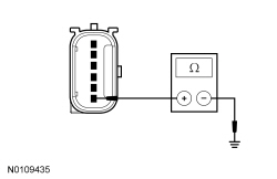 | Yes
INSTALL a new keyless entry keypad. REFER to Keyless Entry Keypad . No REPAIR the circuit. | ||||||||||||
| L7 PERFORM THE RFA MODULE SELF-TEST | |||||||||||||
| Yes
GO to L8 . No GO to L10 . | ||||||||||||
| L8 ISOLATE THE KEYLESS ENTRY KEYPAD | |||||||||||||
| Yes
GO to L9 . No INSTALL a new keyless entry keypad. REFER to Keyless Entry Keypad . | ||||||||||||
| L9 CHECK THE KEYLESS ENTRY KEYPAD INPUT CIRCUITS FOR A SHORT TO GROUND | |||||||||||||
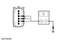 | Yes
GO to L17 . No REPAIR the circuit in question. | ||||||||||||
| L10 CHECK THE RFA MODULE KEYPAD PIDs | |||||||||||||
| Yes
GO to L11 . No GO to L13 . | ||||||||||||
| L11 COMPARE THE KEYPAD CODE | |||||||||||||
NOTE: The permanent keypad code in the scan tool does not display even numbers. If the permanent code has even numbers in it, the scan tool displays an odd number that corresponds with the same button on the keypad. For example, if the keycode contains the number 2, the scan tool displays the number 1 in its place. | Yes
GO to L12 . No PERFORM the keyless entry keypad code reset. REFER to Remote Function Actuator (RFA) Module Keyless Entry Keypad Code Reset in Keyless Entry Keypad Code Programming . | ||||||||||||
| L12 CHECK THE FACTORY ENTRY CODE OPERATION | |||||||||||||
| Yes
The system is operating as designed. INFORM the customer of the correct system operation. No GO to L17 . | ||||||||||||
| L13 CHECK THE KEYLESS ENTRY KEYPAD INPUT CIRCUITS | |||||||||||||
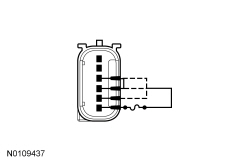 | Yes
INSTALL a new keyless entry keypad. REFER to Keyless Entry Keypad . No GO to L14 . | ||||||||||||
| L14 CHECK THE KEYLESS ENTRY KEYPAD INPUT CIRCUITS FOR AN OPEN | |||||||||||||
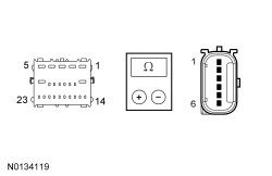 | Yes
GO to L15 . No REPAIR the circuit in question. | ||||||||||||
| L15 CHECK THE KEYLESS ENTRY KEYPAD INPUT CIRCUITS FOR A SHORT TO EACH OTHER | |||||||||||||
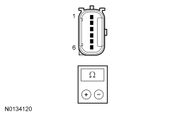 | Yes
GO to L17 . No REPAIR the circuits in question. | ||||||||||||
| L16 CHECK FOR CORRECT BCM OPERATION | |||||||||||||
| Yes
CHECK On-Line Automotive Service Information System (OASIS) for any applicable TSBs . If a TSB exists for this concern, DISCONTINUE this test and FOLLOW TSB instructions. If no TSBs address this concern, INSTALL a new BCM . REFER to Section 419-10 . No The system is operating correctly at this time. The concern may have been caused by module connections. ADDRESS the root cause of any connector or pin issues. | ||||||||||||
| L17 CHECK FOR CORRECT RFA MODULE OPERATION | |||||||||||||
| Yes
CHECK On-Line Automotive Service Information System (OASIS) for any applicable TSBs . If a TSB exists for this concern, DISCONTINUE this test and FOLLOW TSB instructions. If no TSBs address this concern, INSTALL a new RFA module. REFER to Section 419-10 . No The system is operating correctly at this time. The concern may have been caused by module connections. ADDRESS the root cause of any connector or pin issues. |
Pinpoint Test M: The Keyless Entry Keypad Illumination Is Inoperative Or Always On
Diagnostics in this manual assume a certain skill level and knowledge of Ford-specific diagnostic practices. Refer to Diagnostic Methods in Section 100-00 for information about these practices.
Refer to Wiring Diagrams Cell 117 , Remote Keyless Entry and Alarm for schematic and connector information.
Refer to System Operation, Keyless Entry Keypad in Handles, Locks, Latches and Entry Systems .
Refer to Component Description, Keyless Entry Keypad in Handles, Locks, Latches and Entry Systems .
RFA Module DTC Fault Trigger Conditions
| DTC | Description | Fault Trigger Conditions |
|---|---|---|
| Keypad Illumination Output: Circuit Short To Ground | Sets when the RFA module detects a short to ground from the keyless entry keypad illumination output circuit. |
| Keypad Illumination Output: Circuit Short To Ground | Sets when the RFA module detects an open or short to voltage from the keyless entry keypad illumination output circuit. |
Visual Inspection and Diagnostic Pre-checks
| Test Step | Result / Action to Take |
|---|---|
| M1 CHECK THE KEYLESS ENTRY KEYPAD ILLUMINATION | |
NOTE: It is normal operation for the keypad to illuminate when the illuminated entry/exit feature is active. Make sure all the doors are closed and the feature times out. | Yes
GO to M2 . No GO to M4 . |
| M2 ISOLATE THE RFA MODULE | |
| Yes
GO to M3 . No GO to M10 . |
| M3 CHECK THE RFA MODULE KEYPAD ILLUMINATION OUTPUT CIRCUIT FOR A SHORT TO VOLTAGE | |
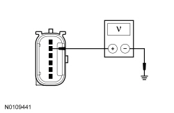 | Yes
REPAIR the circuit. No INSTALL a new keyless entry keypad. REFER to Keyless Entry Keypad . |
| M4 CHECK THE KEYLESS ENTRY KEYPAD OPERATION | |
| Yes
GO to M5 . No GO to Pinpoint Test L . |
| M5 PERFORM THE RFA MODULE SELF-TEST | |
| Yes
GO to M6 . No GO to M8 . |
| M6 CHECK THE KEYLESS ENTRY KEYPAD FOR A SHORT TO GROUND | |
| Yes
GO to M7 . No INSTALL a new keyless entry keypad. REFER to Keyless Entry Keypad . |
| M7 CHECK THE KEYPAD ILLUMINATION OUTPUT CIRCUIT FOR A SHORT TO GROUND | |
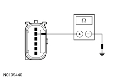 | Yes
GO to M10 . No REPAIR the circuit. |
| M8 CHECK THE RFA MODULE OUTPUT | |
 | Yes
INSTALL a new keyless entry keypad. REFER to Keyless Entry Keypad . No GO to M9 . |
| M9 CHECK THE BCM KEYPAD ILLUMINATION OUTPUT CIRCUIT FOR AN OPEN | |
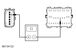 | Yes
GO to M10 . No REPAIR the circuit. |
| M10 CHECK FOR CORRECT RFA MODULE OPERATION | |
| Yes
CHECK On-Line Automotive Service Information System (OASIS) for any applicable TSBs . If a TSB exists for this concern, DISCONTINUE this test and FOLLOW TSB instructions. If no TSBs address this concern, INSTALL a new RFA module. REFER to Section 419-10 . No The system is operating correctly at this time. The concern may have been caused by module connections. ADDRESS the root cause of any connector or pin issues. |
Pinpoint Test N: The RKE Transmitter Is Inoperative
Diagnostics in this manual assume a certain skill level and knowledge of Ford-specific diagnostic practices. Refer to Diagnostic Methods in Section 100-00 for information about these practices.
Refer to System Operation, Remote Keyless Entry (RKE) in Handles, Locks, Latches and Entry Systems .
Refer to Component Description, Integrated Keyhead Transmitter (IKT) in Handles, Locks, Latches and Entry Systems .
RFA Module DTC Fault Trigger Conditions
| DTC | Description | Fault Trigger Conditions |
|---|---|---|
| Remote Keyless Entry Synchronization: Algorithm Based Failures | Sets when the RFA module detects the rolling counter received from an RKE transmitter is 1,024 times greater than the rolling counter stored in the RFA module. |
| External Receiver: No Signal | Sets when the RFA module loses communication with the TPM module. |
Visual Inspection and Diagnostic Pre-checks
| Test Step | Result / Action to Take |
|---|---|
| N1 CHECK FOR THE CORRECT IA KEYS | |
NOTE: A least 2 programmed IA keys must be present to begin diagnosis of the RKE system. | Yes
GO to N2 . No The system cannot be tested without the correct IA keys. INFORM the customer that at least 2 correct IA keys must be present to proceed with diagnosis of the system. |
| N2 CHECK THE RKE OPERATION WHEN THE TPM MODULE IS IN AN AWAKE MODE | |
| Yes
GO to N3 . No GO to N4 . |
| N3 CHECK THE RKE OPERATION WHEN THE TPM MODULE IS IN A SLEEP MODE | |
| Yes
The system is operating correctly at this time. No GO to N13 . |
| N4 CHECK FOR RFA MODULE DTCs | |
| Yes
For DTC B10AB:06, GO to N5 . For DTC U201F:31, GO to N9 . For all other DTCs, REFER to RFA Module DTC Chart in this section. No If an individual IA key has no RKE functionality, GO to N7 . If both IA keys have no RKE functionality, GO to N9 . |
| N5 RESYNCHRONIZE THE INOPERATIVE IA KEY | |
| Yes
The system is OK. The concern was cause by an IA key out of synchronization. No GO to N6 . |
| N6 RESYNCHRONIZE THE INOPERATIVE IA KEY USING THE SECOND IA KEY | |
| Yes
The system is OK. The concern was cause by an IA key out of synchronization. No GO to N7 . |
| N7 CHECK THE IA KEY TRANSPONDER | |
| Yes
GO to N8 . No REFER to Section 419-01C , The Engine Does Not Start or Unable To Turn Ignition On. |
| N8 CHECK THE IA KEY BATTERY | |
| Yes
REPLACE the suspect IA key. PROGRAM the new IA key. REFER to Key Programming Using Diagnostic Equipment in Section 419-01C . INFORM the customer that any IA keys not present need to be programmed. No INSTALL a new battery (make sure the battery is seated correctly). DO NOT reprogram the IA key (weak or dead batteries do not erase IA key from memory). |
| N9 CHECK FOR COMMUNICATION WITH THE TPM MODULE | |
| Yes
GO to N10 . No REFER to Section 418-00 , The Tire Pressure Monitor (TPM) Module Does Not Respond To The Scan Tool. |
| N10 CHECK THE TPM MODULE LIN CIRCUIT FOR A SHORT TO VOLTAGE | |
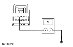 | Yes
REPAIR the circuit. No GO to N11 . |
| N11 CHECK THE TPM MODULE LIN CIRCUIT FOR A SHORT TO GROUND | |
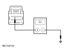 | Yes
GO to N12 . No REPAIR the circuit. |
| N12 CHECK THE TPM MODULE LIN CIRCUIT FOR AN OPEN | |
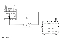 | Yes
GO to N13 . No REPAIR the circuit. |
| N13 CHECK FOR CORRECT TPM MODULE OPERATION | |
| Yes
CHECK On-Line Automotive Service Information System (OASIS) for any applicable TSBs . If a TSB exists for this concern, DISCONTINUE this test and FOLLOW TSB instructions. If no TSBs address this concern, INSTALL a new TPM module. REFER to Section 204-04 . CLEAR the DTCs. REPEAT the self-test. If the concern is still present, GO to N14 . No The system is operating correctly at this time. The concern may have been caused by module connections. ADDRESS the root cause of any connector or pin issues. |
| N14 CHECK FOR CORRECT BCM OPERATION | |
| Yes
CHECK On-Line Automotive Service Information System (OASIS) for any applicable TSBs . If a TSB exists for this concern, DISCONTINUE this test and FOLLOW TSB instructions. If no TSBs address this concern, INSTALL a new BCM . REFER to Section 419-10 . No The system is operating correctly at this time. The concern may have been caused by module connections. ADDRESS the root cause of any connector or pin issues. |
Pinpoint Test O: An Individual Button Or Feature Is Inoperative From The RKE Transmitter
Diagnostics in this manual assume a certain skill level and knowledge of Ford-specific diagnostic practices. Refer to Diagnostic Methods in Section 100-00 for information about these practices.
Refer to System Operation, Remote Keyless Entry (RKE) in Handles, Locks, Latches and Entry Systems .
Refer to Component Description, Integrated Keyhead Transmitter (IKT) in Handles, Locks, Latches and Entry Systems .
Visual Inspection and Diagnostic Pre-checks
| Test Step | Result / Action to Take |
|---|---|
| O1 VERIFY THE DOOR LOCK OPERATION | |
| Yes
GO to O2 . No GO to Pinpoint Test H . |
| O2 VERIFY THE HORN OPERATION | |
| Yes
GO to O3 . No REFER to Section 413-06 . |
| O3 VERIFY THE HAZARD LAMP OPERATION | |
| Yes
GO to O4 . No REFER to Section 417-01 . |
| O4 VERIFY THE POWER LIFTGATE OPERATION | |
| Yes
For vehicles equipped with the factory remote start, GO to O5 . For vehicles not equipped with the factory remote start, REPLACE the suspect IA key. PROGRAM the new IA key. REFER to Key Programming Using Diagnostic Equipment in Section 419-01C . INFORM the customer that any IA keys not present need to be programmed. No REFER to Section 501-03 . |
| O5 VERIFY THE REMOTE START BUTTON INPUT | |
| Yes
REFER to Section 303-06 . No REPLACE the suspect IA key. PROGRAM the new IA key. REFER to Key Programming Using Diagnostic Equipment in Section 419-01C . INFORM the customer that any IA keys not present need to be programmed. |
Pinpoint Test P: The RKE Transmitter Has Poor Range Performance
Diagnostics in this manual assume a certain skill level and knowledge of Ford-specific diagnostic practices. Refer to Diagnostic Methods in Section 100-00 for information about these practices.
The RKE transmitter has a normal operating range of 20 m (66 ft). The TPM module has an internal antenna to receive the RKE transmitter signal.
Visual Inspection and Diagnostic Pre-checks
NOTE: A least 2 programmed IA keys must be present to begin diagnosis of the RKE system.
| Test Step | Result / Action to Take |
|---|---|
| P1 CHECK FOR THE CORRECT RKE TRANSMITTERS | |
| Yes
GO to P2 . No The system cannot be tested without the correct RKE transmitters. INFORM the customer that the correct RKE transmitters must be present to proceed with diagnosis of the system. |
| P2 CHECK ALL THE RKE TRANSMITTERS FOR POOR RANGE PERFORMANCE | |
NOTE: The 20 m (66 ft) measurement of range is not the standard but is a guideline that clearly indicates a vehicle is experiencing normal range performance. | Yes
GO to P4 . No GO to P3 . |
| P3 CHECK THE IA KEY BATTERY | |
| Yes
REPLACE the suspect IA key. PROGRAM the new IA key. REFER to Key Programming Using Diagnostic Equipment in Section 419-01C . INFORM the customer that any IA keys not present need to be programmed. No INSTALL a new battery (make sure the battery seats correctly). DO NOT reprogram the IA key (weak or dead batteries do not erase IA keys from memory). |
| P4 CHECK THE LOCATION OF THE VEHICLE AND THE APPROACH ANGLES AROUND THE VEHICLE | |
NOTE: The RKE transmitter range performance may be degraded in certain locations. For example, if the vehicle is within 0.8 km (0.5 miles) of high-power devices or radio/TV towers, the operating distance of the RKE transmitters may be reduced. | Yes
GO to P5 . No The system is operating correctly at this time. The range may have been affected by environmental interference. |
| P5 CHECK FOR CORRECT TPM MODULE OPERATION | |
| Yes
CHECK On-Line Automotive Service Information System (OASIS) for any applicable TSBs . If a TSB exists for this concern, DISCONTINUE this test and FOLLOW TSB instructions. If no TSBs address this concern, INSTALL a new TPM Module. REFER to Section 204-04 . No The system is operating correctly at this time. The concern may have been caused by module connections. ADDRESS the root cause of any connector or pin issues. |
Pinpoint Test Q: A Front Door IA Feature Is Inoperative
Diagnostics in this manual assume a certain skill level and knowledge of Ford-specific diagnostic practices. Refer to Diagnostic Methods in Section 100-00 for information about these practices.
Refer to Wiring Diagrams Cell 117 , Remote Keyless Entry and Alarm for schematic and connector information.
Refer to System Operation, Intelligent Access (IA) in Handles, Locks, Latches and Entry Systems .
RFA Module DTC Fault Trigger Conditions
| DTC | Description | Fault Trigger Conditions |
|---|---|---|
| Passenger Door External Antenna: General Electrical Failure | Sets when the RFA module detects an open, a short to ground or short to voltage from the right front door IA antenna circuits. |
| Driver Door External Antenna: General Electrical Failure | Sets when the RFA module detects an open, a short to ground or short to voltage from the left front door IA antenna circuits. |
| Left Front Door Handle Proximity Sensor: Circuit Short To Ground | Sets when the RFA module detects a short to ground from the left front door handle lock/unlock input circuit. |
| Left Front Door Handle Proximity Sensor: Circuit Short To Battery or Open | Sets when the RFA module detects a short to voltage or an open from the left front door handle lock/unlock input circuit. |
| Right Front Door Handle Proximity Sensor: Circuit Short To Ground | Sets when the RFA module detects a short to ground from the right front door handle lock/unlock input circuit. |
| Right Front Door Handle Proximity Sensor: Circuit Short To Battery or Open | Sets when the RFA module detects a short to voltage or an open from the right front door handle lock/unlock input circuit. |
Visual Inspection and Diagnostic Pre-checks
NOTE: The IA feature is a programmable parameter and can be enabled/disabled with a scan tool. If the feature is disabled, the IA feature to enter the vehicle and passive starting is inoperative. To start the vehicle, the IA key must be placed in the backup transceiver slot.
| Test Step | Result / Action to Take | |||||||||||||||
|---|---|---|---|---|---|---|---|---|---|---|---|---|---|---|---|---|
| Q1 CHECK THE DOOR LOCK OPERATION | ||||||||||||||||
| Yes
GO to Q2 . No GO to Pinpoint Test H . | |||||||||||||||
| Q2 CHECK THE RKE OPERATION | ||||||||||||||||
| Yes
GO to Q3 . No GO to Pinpoint Test N . | |||||||||||||||
| Q3 CHECK THE IA LOCK AND UNLOCK CAPACITIVE SENSOR PIDs | ||||||||||||||||
NOTE: When the monitoring the capacitive sensor PIDs, it is best to select a graph view. When a sensor is touched, the PID state rapidly switches between ON and OFF. | Yes
GO to Q11 . No GO to Q4 . | |||||||||||||||
| Q4 CHECK THE RECORDED RFA MODULE DTCs FROM THE SELF-TEST | ||||||||||||||||
| Yes
GO to Q5 . No GO to Q7 . | |||||||||||||||
| Q5 ISOLATE THE SUSPECT EXTERIOR DOOR HANDLE AS THE CAUSE OF THE SHORT TO GROUND DTC | ||||||||||||||||
| Yes
GO to Q6 . No INSTALL a new exterior door handle for the handle in question. REFER to Exterior Door Handle . | |||||||||||||||
| Q6 CHECK THE LOCK AND UNLOCK CAPACITIVE SENSOR INPUT CIRCUIT FOR A SHORT TO GROUND | ||||||||||||||||
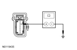 | Yes
GO to Q15 . No REPAIR the circuit in question. | |||||||||||||||
| Q7 ISOLATE THE SUSPECT EXTERIOR DOOR HANDLE | ||||||||||||||||
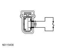 | Yes
REMOVE the jumper wire. INSTALL a new exterior door handle for the handle in question. REFER to Exterior Door Handle . No REMOVE the jumper wire. GO to Q8 . | |||||||||||||||
| Q8 CHECK THE LOCK AND UNLOCK CAPACITIVE SENSOR INPUT CIRCUIT FOR A SHORT TO VOLTAGE | ||||||||||||||||
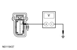 | Yes
REPAIR the circuit in question. No GO to Q9 . | |||||||||||||||
| Q9 CHECK THE LOCK AND UNLOCK CAPACITIVE SENSOR INPUT CIRCUIT FOR AN OPEN | ||||||||||||||||
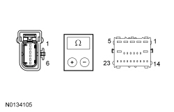 | Yes
GO to Q10 . No REPAIR the circuit in question. | |||||||||||||||
| Q10 CHECK THE LOCK AND UNLOCK CAPACITIVE SENSOR GROUND CIRCUIT FOR AN OPEN | ||||||||||||||||
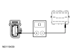 | Yes
GO to Q15 . No REPAIR the circuit. | |||||||||||||||
| Q11 CHECK THE EXTERNAL ANTENNA | ||||||||||||||||
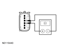 | Yes
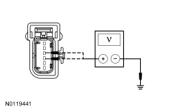
GO to Q12 . No INSTALL a new exterior door handle for the handle in question. REFER to Exterior Door Handle . | |||||||||||||||
| Q12 CHECK THE EXTERNAL ANTENNA CIRCUITS FOR A SHORT TO VOLTAGE | ||||||||||||||||
 | Yes
REPAIR the circuit in question. No GO to Q13 . | |||||||||||||||
| Q13 CHECK THE EXTERNAL ANTENNA CIRCUITS FOR A SHORT TO GROUND | ||||||||||||||||
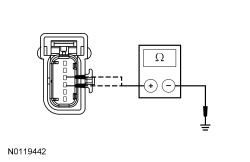 | Yes
GO to Q14 . No REPAIR the circuit in question. | |||||||||||||||
| Q14 CHECK THE EXTERNAL ANTENNA CIRCUITS FOR AN OPEN | ||||||||||||||||
 | Yes
GO to Q15 . No REPAIR the circuit in question. | |||||||||||||||
| Q15 CHECK FOR CORRECT RFA MODULE OPERATION | ||||||||||||||||
| Yes
CHECK On-Line Automotive Service Information System (OASIS) for any applicable TSBs . If a TSB exists for this concern, DISCONTINUE this test and FOLLOW TSB instructions. If no TSBs address this concern, INSTALL a new RFA Module. REFER to Section 419-10 . No The system is operating correctly at this time. The concern may have been caused by module connections. ADDRESS the root cause of any connector or pin issues. |
Pinpoint Test R: The Liftgate IA Feature Is Inoperative
Diagnostics in this manual assume a certain skill level and knowledge of Ford-specific diagnostic practices. Refer to Diagnostic Methods in Section 100-00 for information about these practices.
Refer to Wiring Diagrams Cell 117 , Remote Keyless Entry and Alarm for schematic and connector information.
Refer to System Operation, Intelligent Access (IA) in Handles, Locks, Latches and Entry Systems .
RFA Module DTC Fault Trigger Conditions
| DTC | Description | Fault Trigger Conditions |
|---|---|---|
| Exterior Trunk Antenna: General Electrical Failure | Sets when the RFA module detects an open, a short to ground or short to voltage from the liftgate IA antenna circuits. |
Visual Inspection and Diagnostic Pre-checks
NOTE: The IA feature is a programmable parameter and can be enabled/disabled with a scan tool. If the feature is disabled, the IA feature to enter the vehicle and passive starting is inoperative. To start the vehicle, the IA key must be placed in the backup transceiver slot.
| Test Step | Result / Action to Take | |||||||||
|---|---|---|---|---|---|---|---|---|---|---|
| R1 CHECK THE POWER LIFTGATE OPERATION FROM THE LIFTGATE RELEASE SWITCH | ||||||||||
| Yes
GO to R2 . No REFER to Section 501-03 . | |||||||||
| R2 CHECK THE RKE OPERATION | ||||||||||
| Yes
GO to R3 . No GO to Pinpoint Test O . | |||||||||
| R3 CHECK THE LIFTGATE IA ANTENNA | ||||||||||
 | Yes
GO to R4 . No INSTALL a new liftgate IA antenna. REFER to Intelligent Access (IA) Antenna — Liftgate . | |||||||||
| R4 CHECK THE LIFTGATE IA ANTENNA CIRCUITS FOR A SHORT TO VOLTAGE | ||||||||||
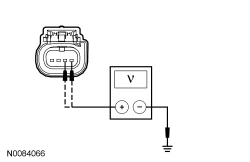 | Yes
REPAIR the circuit in question. No GO to R5 . | |||||||||
| R5 CHECK THE LIFTGATE IA ANTENNA CIRCUITS FOR A SHORT TO GROUND | ||||||||||
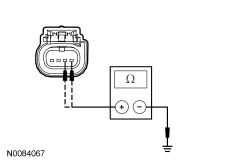 | Yes
GO to R6 . No REPAIR the circuit in question. | |||||||||
| R6 CHECK THE LIFTGATE IA ANTENNA CIRCUITS FOR AN OPEN | ||||||||||
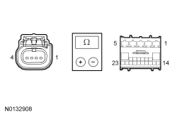 | Yes
GO to R7 . No REPAIR the circuit in question. | |||||||||
| R7 CHECK FOR CORRECT RFA MODULE OPERATION | ||||||||||
| Yes
CHECK On-Line Automotive Service Information System (OASIS) for any applicable TSBs . If a TSB exists for this concern, DISCONTINUE this test and FOLLOW TSB instructions. If no TSBs address this concern, INSTALL a new RFA module. REFER to Section 419-10 . No The system is operating correctly at this time. The concern may have been caused by module connections. ADDRESS the root cause of any connector or pin issues. |
Pinpoint Test S: DTCs B106E, B106F
Diagnostics in this manual assume a certain skill level and knowledge of Ford-specific diagnostic practices. Refer to Diagnostic Methods in Section 100-00 for information about these practices.
The DDM controls the output of several vehicle systems by means of solid state drivers. A DTC sets when an overload occurs on any of these drivers. The module also tracks the number of repetitive faults on each of these circuits, and then it compares that said number of overloads to 3 progressive thresholds established for each circuit. If the third threshold has not been met, the DTC for the affected circuit can be cleared by eliminating the fault, clearing the DTCs and then running a self-test.
At the point that each of the first 2 thresholds is met, DTC B106E sets along with a DTC related to the affected circuit. Once the final (third) threshold has been met, the affected output is permanently disabled, and DTC B106F sets, at which time the DDM must be replaced.
DDM DTC Fault Trigger Conditions
| DTC | Description | Fault Trigger Conditions |
|---|---|---|
| Solid State Driver Disabled Due to Short Circuit | Sets when the DDM has disabled an output circuit due to a repetitive fault that overloads said circuit. A corresponding DTC for the circuit in question is also set. |
| Module Disabled Due to External Fault | Sets when the DDM has permanently disabled one or more output functions due to a repetitive circuit overload. DTC B1342 also sets at this time. |
When DTC B1342 is set because the module has reached a third threshold and the DDM has permanently disabled an output, no DTCs can be cleared from the DDM . Using the module self-test to confirm a repair is not possible and a measurement using a digital multimeter of the affected output circuit is required to make sure the fault condition no longer exists.
| Test Step | Result / Action to Take |
|---|---|
| S1 REVIEW THE DTCs | |
NOTICE: First follow the necessary diagnostics to resolve DTC B106E and any other present DTCs (ignoring B106F). DTC B106E is only present when there is another DTC due to software or circuitry issues that must be resolved before another self-test is run. DTC B106F is only present once the final threshold has been met. Failure to correct the fault condition first may cause damage to the new DDM , resulting in a repeat repair. | Yes
CORRECT the DTCs. REFER to Driver Door Module (DDM) DTC Chart in this section. After the repair, GO to S2 . No GO to S2 . |
| S2 REPEAT THE DDM SELF-TEST | |
| Yes
INSTALL a new DDM . REFER to Driver Door Module (DDM) . No The system is operating correctly at this time. The circuit short has been repaired. |
Pinpoint Test T: DTC B1317
Diagnostics in this manual assume a certain skill level and knowledge of Ford-specific diagnostic practices. Refer to Diagnostic Methods in Section 100-00 for information about these practices.
The DDM constantly monitors the voltage supply circuit. If the voltage exceeds a set parameter, the DDM sets a DTC.
DDM DTC Fault Trigger Conditions
| DTC | Description | Fault Trigger Conditions |
|---|---|---|
| Battery Voltage High | Sets when the DDM detects battery voltage above 15 volts on the voltage supply circuit. |
NOTE: DTC B1317 may be stored in the module memory due to previous battery charging or vehicle jump starting events.
| Test Step | Result / Action to Take |
|---|---|
| T1 CHECK FOR DTCs B1317, B1676 OR P0563 SET IN OTHER MODULES | |
| Yes
REFER to Section 414-00 to diagnose an overcharging condition. No GO to T2 . |
| T2 CHECK THE BATTERY VOLTAGE | |
| Yes
REFER to Section 414-00 to diagnose an overcharging condition. No GO to T3 . |
| T3 RECHECK FOR DTC B1317 | |
| Yes
INSTALL a new DDM . REFER to Driver Door Module (DDM) . No The system is operating normally at this time. The DTC may have been set previously during battery charging or while jump starting the vehicle. |
Pinpoint Test U: DTC B1318
Diagnostics in this manual assume a certain skill level and knowledge of Ford-specific diagnostic practices. Refer to Diagnostic Methods in Section 100-00 for information about these practices.
Refer to Wiring Diagrams Cell 13 , Power Distribution/SJB for schematic and connector information.
The DDM constantly monitors the voltage supply circuit. If the voltage exceeds a set parameter, the DDM sets a DTC.
DDM DTC Fault Trigger Conditions
| DTC | Description | Fault Trigger Conditions |
|---|---|---|
| Battery Voltage Low | Sets when the DDM detects battery voltage below 10 volts. |
| Test Step | Result / Action to Take |
|---|---|
| U1 RECHECK THE DDM DTCs | |
| Yes
GO to U2 . No The system is operating normally at this time. The DTC may have been set due to a previous low battery voltage condition. |
| U2 CHECK FOR CHARGING SYSTEM DTCs IN THE PCM | |
| Yes
REFER to Section 414-00 . No GO to U3 . |
| U3 CHECK THE BATTERY CONDITION AND STATE OF CHARGE | |
| Yes
GO to U4 . No REFER to Section 414-00 . |
| U4 CHECK THE DDM VOLTAGE PID (VBATDDM) | |
| Yes
GO to U7 . No GO to U5 . |
| U5 CHECK THE DDM VOLTAGE SUPPLY CIRCUIT FOR HIGH RESISTANCE | |
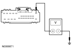 | Yes
GO to U6 . No REPAIR the circuit. |
| U6 CHECK THE DDM GROUND CIRCUIT FOR HIGH RESISTANCE | |
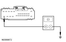 | Yes
GO to U7 . No REPAIR the circuit. |
| U7 CHECK FOR CORRECT DDM OPERATION | |
| Yes
CHECK On-Line Automotive Service Information System (OASIS) for any applicable TSBs . If a TSB exists for this concern, DISCONTINUE this test and FOLLOW TSB instructions. If no TSBs address this concern, INSTALL a new DDM . REFER to Driver Door Module (DDM) . No The system is operating correctly at this time. The concern may have been caused by module connections. ADDRESS the root cause of any connector or pin issues. |
Pinpoint Test V: DTC U0140
Diagnostics in this manual assume a certain skill level and knowledge of Ford-specific diagnostic practices. Refer to Diagnostic Methods in Section 100-00 for information about these practices.
Refer to Wiring Diagrams Cell 117 , Remote Keyless Entry and Alarm for schematic and connector information.
The DDM and the BCM communicate using the MS-CAN . Messages are exchanged between the modules on the MS-CAN for the purposes of determining what functions are being carried out.
DDM DTC Fault Trigger Conditions
| DTC | Description | Fault Trigger Conditions |
|---|---|---|
| Lost Communication With Body Control Module (GEM) | Sets by the DDM if data messages received from the BCM over the MS-CAN are missing for 15 seconds or longer. |
| Test Step | Result / Action to Take |
|---|---|
| V1 VERIFY CUSTOMER CONCERN | |
| Yes
GO to V2 . No The system is operating normally at this time. The DTC may have been set due to high network traffic or intermittent fault condition. |
| V2 CHECK THE COMMUNICATION NETWORK | |
| Yes
GO to V3 . No REFER to Section 418-00 , The Body Control Module (BCM) Does Not Respond To The Scan Tool. |
| V3 RETRIEVE THE RECORDED DTCs FROM THE SELF-TEST | |
| Yes
For DTC B1317, GO to Pinpoint Test T . For DTC B1318, GO to Pinpoint Test U . No GO to V4 . |
| V4 RECHECK THE DDM DTCs | |
NOTE: If new modules were installed prior to the DTC being set, the module configuration may be incorrectly set during PMI or the PMI may not have been carried out. | Yes
GO to V5 . No The system is operating correctly at this time. The DTC may have been set due to high network traffic or intermittent fault condition. |
| V5 CHECK FOR DTC U0140 IN OTHER MODULES | |
| Yes
INSTALL a new BCM . REFER to Section 419-10 . No INSTALL a new DDM . REFER to Driver Door Module (DDM) . |