
FLU77-4 or equivalent
SECTION 501-17: Roof Opening Panel
| 2014 Flex Workshop Manual
|
DIAGNOSIS AND TESTING
| Procedure revision date: 05/02/2013
|
 | Fluke 77-IV Digital Multimeter
FLU77-4 or equivalent |
Principles of Operation
The roof opening panel assembly uses an integrated motor and module to operate the roof opening panel. The roof opening panel motor and module are installed new as an assembly. The roof opening panel is an electronically operated glass panel that can be opened, closed or vented by the roof opening panel switch.
The roof opening panel motor must be initialized when repairs are carried out on any part of the roof opening panel system, including: whenever the roof opening panel motor has been removed from the roof opening panel system, the roof opening panel glass has been removed from the roof opening panel system, the roof opening panel assembly has been removed from the vehicle, a new roof opening panel motor has been installed, a new roof opening panel glass has been installed or a new roof opening panel assembly has been installed.
Inspection and Verification
Visual Inspection Chart
| Mechanical | Electrical |
|---|---|
|
|
Symptom Chart — Roof Opening Panel
| Condition | Possible Sources | Action |
|---|---|---|
|
| |
|
| |
|
| |
|
|
|
|
|
|
Symptom Chart — NVH
| Condition | Possible Sources | Action |
|---|---|---|
|
| |
|
| |
|
|
Pinpoint Tests
Pinpoint Test A: The Roof Opening Panel Has Excessive Wind Noise
When the roof opening panel glass is completely closed, it is flush with the roof panel.
| Test Step | Result / Action to Take |
|---|---|
| A1 VERIFY ROOF OPENING PANEL NOISE | |
| Yes
GO to A4 . No GO to A2 . |
| A2 CHECK THE ROOF OPENING PANEL WEATHERSTRIP | |
NOTE: Make sure the weatherstrip is secured to the glass, not cut, cracked, pinched, loose or obstructed in CLOSED, VENT and OPEN positions. | Yes
GO to A3 . No INSTALL a new roof opening panel weatherstrip. REFER to Roof Opening Panel — Exploded View in this section. TEST the system for normal operation. |
| A3 CHECK ROOF OPENING PANEL ALIGNMENT | |
| Yes
CHECK for correct installation of the roof opening panel and motor/module. REFER to Roof Opening Panel — Exploded View , Roof Opening Panel Frame and Roof Opening Panel Motor in this section. TEST the system for normal operation. No ALIGN the roof opening panel. REFER to Roof Opening Panel Alignment in this section. TEST the system for normal operation. |
| A4 CHECK THE AIR DEFLECTOR | |
| Yes
PARTIALLY close the roof opening panel until the noise is eliminated. If the noise is eliminated, INFORM the customer that changing glass location will eliminate the wind noise. If the wind noise is not eliminated, RE-ALIGN panel. TEST the system for normal operation. No INSTALL new air deflector assembly. REFER to Air Deflector in this section. TEST the system for normal operation. |
Pinpoint Test B: The Roof Opening Panel Leaks
When the roof opening panel glass is completely closed, it should be within specifications. Refer to Specifications in this section.
| Test Step | Result / Action to Take |
|---|---|
| B1 CHECK THE ALIGNMENT OF THE ROOF OPENING PANEL | |
| Yes
GO to B2 . No ALIGN the roof opening panel. REFER to Roof Opening Panel Alignment in this section. TEST the system for normal operation. |
| B2 CHECK THE ROOF OPENING PANEL DRAIN HOSES | |
| Yes
GO to B3 . No REPAIR or INSTALL a new roof opening panel drain hose(s). TEST the system for normal operation. |
| B3 CHECK THE ROOF OPENING PANEL DRAIN HOSE ATTACHMENT POINTS | |
| Yes
GO to B4 . No REPAIR or INSTALL a new roof opening panel frame. REFER to Roof Opening Panel Frame in this section. TEST the system for normal operation. |
| B4 CHECK THE ROOF OPENING PANEL REAR TROUGH CONDITION | |
| Yes
GO to B5 . No REPAIR or INSTALL a new roof opening rear trough. REFER to Trough Assembly in this section. TEST the system for normal operation. |
| B5 CHECK THE CONDITION OF THE ROOF OPENING GLASS PANEL | |
| Yes
INSTALL a new roof opening panel glass. REFER to Roof Opening Panel Glass in this section. TEST the system for normal operation No REPAIR or INSTALL a new roof opening panel frame. REFER to Roof Opening Panel Frame in this section. TEST the system for normal operation. |
Pinpoint Test C: The Roof Opening Panel Rattles
When the roof opening panel glass is completely closed, it should be within specifications. Refer to Specifications in this section. All components should be secured correctly.
| Test Step | Result / Action to Take |
|---|---|
| C1 CHECK THE ROOF OPENING PANEL TIGHTNESS | |
| Yes
ALIGN the roof opening panel. REFER to Roof Opening Panel Alignment in this section. TEST the system for normal operation. No GO to C2 . |
| C2 CHECK THE ROOF OPENING PANEL TRACKS | |
| Yes
GO to C3 . No REMOVE all the roof opening panel track obstructions and REPAIR the roof opening panel tracks. If the roof opening panel tracks cannot be repaired, INSTALL a new roof opening panel frame. REFER to Roof Opening Panel Frame in this section. TEST the system for normal operation. |
| C3 CHECK THE ROOF OPENING PANEL WATER TROUGH AND TROUGH GUIDES | |
| Yes
GO to C4 . No REMOVE all obstructions from the roof opening panel water trough guides and install securely. INSTALL a new roof opening panel frame if the water trough guides are damaged. REFER to Trough Assembly and Roof Opening Panel Frame in this section. TEST the system for normal operation. |
| C4 CHECK THE ROOF OPENING PANEL SHIELD (SUNSHADE) | |
| Yes
GO to C5 . No INSTALL the roof opening panel shield correctly. REFER to Roof Opening Panel Shield in this section. TEST the system for normal operation. |
| C5 CHECK THE ROOF OPENING PANEL AIR DEFLECTOR ASSEMBLY | |
| Yes
GO to C6 . No REMOVE all obstructions and REPAIR or INSTALL a new roof opening panel air deflector assembly. REFER to Air Deflector in this section. TEST the system for normal operation. |
| C6 CHECK THE ROOF OPENING PANEL LIFTER ASSEMBLIES | |
| Yes
GO to C7 . No REMOVE all obstructions from the roof opening panel lifter assemblies and REPAIR any damage. If the roof opening panel lifter assemblies cannot be repaired, INSTALL a new roof opening panel frame. REFER to Roof Opening Panel — Exploded View and Roof Opening Panel Frame in this section. TEST the system for normal operation. |
| C7 CHECK ROOF OPENING PANEL FRAME INSTALLATION | |
| Yes
GO to C8 . No TIGHTEN the loose fasteners or REINSTALL the roof opening panel frame. REFER to Roof Opening Panel — Exploded View and Roof Opening Panel Frame in this section. TEST the system for normal operation. |
| C8 CHECK THE ROOF OPENING PANEL FRAME FOR RATTLES | |
| Yes
INSTALL a suitable sound damper material to correct the condition. If the rattle still persists, INSTALL a new roof opening panel frame. REFER to Roof Opening Panel — Exploded View and Roof Opening Panel Frame in this section. TEST the system for normal operation. No INSTALL a new roof opening panel frame. REFER to Roof Opening Panel Frame in this section. TEST the system for normal operation. |
Pinpoint Test D: The Roof Opening Panel is Noisy During Operation
The roof opening panel operates smoothly and quietly while opening and closing.
| Test Step | Result / Action to Take |
|---|---|
| D1 CHECK THE ROOF OPENING PANEL FOR OBSTRUCTIONS OR DAMAGE | |
| Yes
REMOVE all obstructions. REPAIR any damage. If the damage cannot be repaired, INSTALL a new roof opening panel frame. REFER to Roof Opening Panel Frame in this section. TEST the system for normal operation. No GO to D2 . |
| D2 CHECK THE ROOF OPENING PANEL OPERATION | |
| Yes
ADJUST the roof opening panel. REFER to Roof Opening Panel Alignment in this section. TEST the system for normal operation. No GO to D3 . |
| D3 CHECK THE ROOF OPENING PANEL TRACKS | |
| Yes
GO to D4 . No REMOVE all obstructions and REPAIR any damage. If the roof opening panel tracks cannot be repaired, INSTALL a new roof opening panel frame. REFER to Roof Opening Panel Frame in this section. TEST the system for normal operation. |
| D4 CHECK THE ROOF OPENING PANEL SHIELD (SUNSHADE) | |
| Yes
GO to D5 . No REMOVE and REINSTALL the roof opening panel shield. REFER to Roof Opening Panel Shield in this section. TEST the system for normal operation. |
| D5 CHECK THE ROOF OPENING PANEL LIFTER ASSEMBLIES | |
| Yes
GO to D6 . No REMOVE all obstructions and REPAIR any damage. If the roof opening panel lifter assemblies cannot be repaired, INSTALL a new roof opening panel frame. REFER to Roof Opening Panel Frame in this section. TEST the system for normal operation. |
| D6 CHECK THE ROOF OPENING PANEL MOTOR/MODULE | |
| Yes
INSTALL a new roof opening panel motor/module. REFER to Roof Opening Panel Motor in this section. TEST the system for normal operation. No REINSTALL the roof opening panel motor/module. TEST the system for normal operation. If the roof opening panel is still noisy, INSTALL a new roof opening panel frame. REFER to Roof Opening Panel Frame in this section. If the roof opening panel is no longer noisy, the system is operating correctly. The concern may have been caused by an incorrectly installed roof opening panel motor. |
Pinpoint Test E: The Roof Opening Panel Does Not Open or Close
Refer to Wiring Diagrams Cell 101 , Roof Opening Panel for schematic and connector information.
The roof opening panel motor must be initialized when repairs are carried out on any part of the roof opening panel system, including: whenever the roof opening panel motor has been removed from the roof opening panel system, the roof opening panel glass has been removed from the roof opening panel system, the roof opening panel assembly has been removed from the vehicle, a new roof opening panel motor has been installed, a new roof opening panel glass has been installed or a new roof opening panel assembly has been installed. Refer to Roof Opening Panel Motor Initialization in this section.
The roof opening panel uses an integrated motor and module to operate the roof opening panel. A new roof opening panel motor/module is installed as an assembly.
The roof opening panel motor/module receives voltage from the accessory delay relay through circuit CBP41 (BU) when the key is in the ACC or RUN position and voltage at all times through circuit SBP19 (BU/RD). Ground is supplied to the roof opening panel motor/module through circuit GD133 (BK). The roof opening panel motor/module provides ground to the roof opening panel switch through circuit CPR39 (VT/WH). When the roof opening panel SLIDE switch is pulled, a ground signal is sent to the roof opening panel motor/module through circuit CPR40 (YE/OG), which causes the roof opening panel to close. When the roof opening panel SLIDE switch is pressed, a ground signal is sent to the roof opening panel motor/module through circuit CPR31 (VT/BN), which causes the roof opening panel to open.
| Test Step | Result / Action to Take |
|---|---|
| E1 CHECK THE MOTOR/MODULE FOR INITIALIZATION | |
| Yes
GO to E2 . No The system is operating normally at this time. The roof opening panel motor was not initialized. |
| E2 CHECK THE POWER WINDOWS | |
| Yes
GO to E3 . No REFER to Section 501-11 to diagnose the accessory delay relay circuit. |
| E3 CHECK THE ROOF OPENING PANEL SWITCH | |
| Yes
GO to E4 . No INSTALL a new roof opening panel switch. TEST the system for normal operation. |
| E4 CHECK VOLTAGE TO THE ROOF OPENING PANEL MOTOR/MODULE — CIRCUITS CBP41 (BU) AND SBP19 (BU/RD) | |
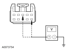 | Yes
GO to E5 . No VERIFY Smart Junction Box (SJB) fuses 19 (25A) and 41 (15A) are OK. If OK, REPAIR the circuit. If not OK, REFER to the Wiring Diagrams manual to identify the possible causes of the circuit short. TEST the system for normal operation. |
| E5 CHECK THE ROOF OPENING PANEL GROUND — CIRCUIT GD133 (BK) | |
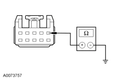 | Yes
GO to E6 . No REPAIR the circuit. TEST the system for normal operation. |
| E6 CHECK CIRCUIT CPR39 (VT/WH) FOR AN OPEN | |
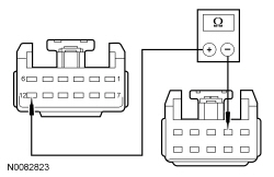 | Yes
CHECK the overhead console jumper harness for loose pins, an open or a short in circuit CPR39 (VT/WH) between the roof opening panel switch socket and overhead console C921-12. If the overhead console jumper harness is not OK, INSTALL a new overhead console jumper harness and TEST the system for normal operation. If the overhead console jumper harness is OK, GO to E7 . No REPAIR the circuit. TEST the system for normal operation. |
| E7 CHECK CIRCUIT CPR40 (YE/OG) FOR AN OPEN | |
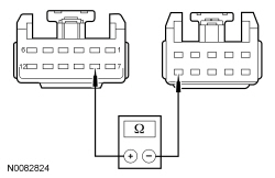 | Yes
CHECK the overhead console jumper harness for loose pins, an open or a short in circuit CPR40 (YE/OG) between the roof opening panel switch socket and overhead console C912-8. If the overhead console jumper harness is not OK, INSTALL a new overhead console jumper harness and TEST the system for normal operation. If the overhead console jumper harness is OK, GO to E8 . No REPAIR the circuit. TEST the system for normal operation. |
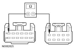
| E8 CHECK CIRCUIT CPR31 (VT/BN) FOR AN OPEN | |
 | Yes
CHECK the overhead console jumper harness for loose pins, an open or a short in circuit CPR31 (VT/BN) between the roof opening panel switch socket and overhead console C912-6. If the overhead console jumper harness is not OK, INSTALL a new overhead console jumper harness, and TEST the system for normal operation. If the overhead console jumper harness is OK, GO to E9 . No REPAIR the circuit. TEST the system for normal operation. |
| E9 CHECK THE ROOF OPENING PANEL MOTOR/MODULE FOR CORRECT OPERATION | |
| Yes
INSTALL a new roof opening panel motor/module. REFER to Roof Opening Panel Motor in this section. TEST the system for normal operation. No The system is operating correctly at this time. Concern may have been caused by a loose or corroded connector. TEST the system for normal operation. |
Pinpoint Test F: The Roof Opening Panel Does Not Open or Close in VENT Position
Refer to Wiring Diagrams Cell 101 , Roof Opening Panel for schematic and connector information.
The roof opening panel motor must be initialized when repairs are carried out on any part of the roof opening panel system, including: whenever the roof opening panel motor has been removed from the roof opening panel system, the roof opening panel glass has been removed from the roof opening panel system, the roof opening panel assembly has been removed from the vehicle, a new roof opening panel motor has been installed, a new roof opening panel glass has been installed or a new roof opening panel assembly has been installed. Refer to Roof Opening Panel Motor Initialization in this section.
The roof opening panel uses an integrated motor and module to operate the roof opening panel. A new roof opening panel motor/module is installed as an assembly.
The roof opening panel motor/module receives voltage from the accessory delay relay through circuit CBP41 (BU) when the key is in the ACC or RUN position. The roof opening panel motor/module provides ground to the roof opening panel switch through circuit CPR39 (VT/WH). When the roof opening panel TILT switch is pressed, a ground signal is sent to the roof opening panel motor/module through circuit CPR38 (WH/BU), which causes the roof opening panel to open to the vent position. When the roof opening panel SLIDE switch is pulled, a ground signal is sent to the roof opening panel motor/module through circuit CPR40 (YE/OG), which causes the roof opening panel to close.
| Test Step | Result / Action to Take |
|---|---|
| F1 CHECK THE MOTOR/MODULE FOR INITIALIZATION | |
| Yes
The system is operating normally at this time. The roof opening panel motor was not initialized. No GO to F2 . |
| F2 CHECK THE ROOF OPENING PANEL SWITCH | |
| Yes
GO to F3 . No INSTALL a new roof opening panel switch. TEST the system for normal operation. |
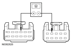
| F3 CHECK CIRCUIT CPR38 (WH/BU) FOR AN OPEN | |
 | Yes
CHECK the overhead console jumper harness for loose pins, an open or a short in circuit CPR38 (WH/BU) between the roof opening panel switch socket and overhead console C912-3. If the overhead console jumper harness is not OK, INSTALL a new overhead console jumper harness and TEST the system for normal operation. If the overhead console jumper harness is OK, GO to F4 . No REPAIR the circuit. TEST the system for normal operation. |
| F4 CHECK CIRCUIT CPR40 (YE/OG) FOR AN OPEN | |
 | Yes
CHECK the overhead console jumper harness for loose pins, an open or a short in circuit CPR40 (YE/OG) between the roof opening panel switch socket and overhead console C912-8. If the overhead console jumper harness is not OK, INSTALL a new overhead console jumper harness and TEST the system for normal operation. If the overhead console jumper harness is OK, GO to F5 . No REPAIR the circuit. TEST the system for normal operation. |
| F5 CHECK THE ROOF OPENING PANEL MOTOR/MODULE FOR CORRECT OPERATION | |
| Yes
INSTALL a new roof opening panel motor/module. REFER to Roof Opening Panel Motor in this section. TEST the system for normal operation. No The system is operating correctly at this time. Concern may have been caused by a loose or corroded connector. TEST the system for normal operation. |