SECTION 211-04: Steering Column
| 2014 Flex Workshop Manual
|
DIAGNOSIS AND TESTING
| Procedure revision date: 05/02/2013
|
Steering Column
Principles of Operation
Power Adjustable Tilt/Telescope Steering Column
The power adjustable tilt/telescope steering column is controlled by the steering column control switch and 2 electric motors that are powered by the
. The steering column control switch is mounted directly to the
on the LH side of the steering column just below the multifunction switch, but is serviceable separately. The steering column control switch is a 4-position, momentary contact switch. When the steering column control switch is moved to any of the 4 positions, it sends a signal to the
to tilt the steering column up or down or telescope the steering column forward or rearward.
The
continuously monitors the steering column tilt and telescoping motors and circuits for faults. If a fault is detected, the
is capable of setting DTCs.
Tilt/Telescoping Motor Sensors
The
receives digital signals from Hall-effect type rotation sensors that are integral to the tilt and telescoping motors. The
uses these signals to calculate the location of the steering column in relation to the full forward/rearward and full up/down positions. The
also uses these signals to store and recall memory positions, carry out the easy entry/exit operations and to make sure the tilt and telescoping motors do not stall against the steering column end of travel in the forward/rearward or up/down directions. The tilt motor is serviced separately from the steering column. The telescoping motor is not serviceable. If a new telescoping motor is needed, a new steering column must be installed.
Jog Mode
If the
loses the signal from either of the motor sensors, the affected steering column motor operates in jog mode. Jog mode allows limited operation of the affected steering column motor using only the steering column control switch. When the steering column control switch is operated in jog mode, the steering column moves in the desired direction for one second, then stops. The steering column control switch must be released, then pressed again in order to move the steering column for an additional second. Jog mode is an indication that there is a tilt or telescoping motor sensor fault. If the adjustable steering column is operating in jog mode, a DTC may set in the
.
Memory Position Programming and Recall
The
monitors steering column position using Hall-effect sensors that are integral to the tilt and telescoping motors. When a memory position is recalled through either the memory SET switch or the
transmitter, the
monitors the Hall-effect sensors and stops sending voltage to the steering column motors once the commanded memory position is reached. If the
receives a steering column switch input during a memory position recall function, the module stops the memory recall and responds to the new steering column switch position input.
When the
transmitter is activated, a message is sent over the
to the
. When the memory SET switch is pressed, the
senses continuity to ground on the switch circuit. When the
receives either the
message or the ground input through the switch circuit, it sends a message over the
to the
. The
acts as a gateway module, relaying the
message that was received from the
to the
over the High Speed Controller Area Network (HS-CAN). The
then sends voltage over the appropriate circuit to the steering column tilt or telescoping motor to adjust the steering column position.
For additional information on setting and recalling a memory position, refer to the Owner's Literature or Memory Position Programming in
Section 501-10
.
Easy Entry/Exit
The easy entry/exit function moves the steering column to the full inward and upward position when the selector lever is in the PARK position and the ignition is selected off (if equipped with a push button start system) or if the ignition switch indicates the ignition key has been removed from the ignition lock cylinder (if equipped with an ignition switch). The
receives an ignition status message over the
. When the ignition status message indicates the ignition key has been removed from the lock cylinder (vehicles with an ignition switch), the
commands the steering column to the full upward/forward position. For vehicles equipped with a push button start system, this occurs when the ignition status message indicates the ignition has transitioned to off. The
cancels this operation if a valid input is received from the steering column control switch or memory position switch.
The
records the current steering column position before powering the steering column for an easy exit operation. This recorded position returns the steering column to this position on the next easy entry operation. During easy entry operation, the steering column is returned to the position previous to the easy exit operation.
The easy entry/exit feature can be activated or deactivated using the message center. Refer to driver controls in the Owner's Literature for additional instructions for using the message center.
Inspection and Verification
- Verify the customer concern.
- Visually inspect for obvious signs of mechanical or electrical damage.
- Visually inspect for obstructions preventing column movement.
Visual Inspection Chart
| Mechanical
| Electrical
|
|---|
- Steering column control switch
- Steering column assembly
| - Wiring, terminals or connectors
- Adjustable steering column tilt motor
- Adjustable steering column telescope motor (part of the steering column assembly)
|
- If an obvious cause for an observed or reported concern is found, correct the cause (if possible) before proceeding to the next step.
NOTE:
Make sure to use the latest scan tool software release.
If the cause is not visually evident, connect the scan tool to the
.
NOTE:
The
LED prove-out confirms power and ground from the
are provided to the
.
If the scan tool does not communicate with the
:
- check the
connection to the vehicle.
- check the scan tool connection to the
.
- refer to
Section 418-00
, No Power To The Scan Tool, to diagnose no power to the scan tool.
- If the scan tool does not communicate with the vehicle:
- verify the ignition is ON.
- For vehicles with
, the air bag warning indicator prove-out (other indicators may NOT prove ignition is ON) confirms ignition ON. If ignition does not turn ON, refer to
Section 211-05
to diagnose no power in RUN.
- verify the scan tool operation with a known good vehicle.
- refer to
Section 418-00
, The PCM Does Not Respond To The Scan Tool, to diagnose no response from the PCM.
- Carry out the network test.
- If the scan tool responds with no communication for one or more modules, refer to
Section 418-00
.
- If the network test passes, retrieve and record
.
- Clear the continuous DTCs and carry out the self test diagnostics for the
.
- If the DTCs retrieved are related to the concern, go to Steering Column Control Module (SCCM) DTC Chart. For all other
DTCs, refer to the Steering Column Control Module (SCCM) DTC Chart in
Section 211-05
.
- If no DTCs related to the concern are retrieved, GO to
Symptom Chart
.
DTC Chart
NOTE:
Diagnostics in this manual assume a certain skill level and knowledge of Ford-specific diagnostic practices. REFER to Diagnostic Methods in
Section 100-00
for information about these practices.
Steering Column Control Module (SCCM) DTC Chart
| DTC
| Description
| Action
|
|---|
| B1298:09
| Steering Column Adjust Up Switch: Component Failure
| INSTALL a new steering column control switch. REFER to
Section 211-05
.
CLEAR the DTCs. VERIFY correct system operation. REPEAT the self-test.
If DTC B1298:09 returns, INSTALL a new
. REFER to
Section 211-05
.
CLEAR the DTCs. VERIFY correct system operation. REPEAT the self-test.
|
| B1299:09
| Steering Column Adjust Down Switch: Component Failure
| INSTALL a new steering column control switch. REFER to
Section 211-05
.
CLEAR the DTCs. VERIFY correct system operation. REPEAT the self-test.
If DTC B1299:09 returns, INSTALL a new
. REFER to
Section 211-05
.
CLEAR the DTCs. VERIFY correct system operation. REPEAT the self-test.
|
| B12A1:09
| Steering Column Adjust Out Switch: Component Failure
| INSTALL a new steering column control switch. REFER to
Section 211-05
.
CLEAR the DTCs. VERIFY correct system operation. REPEAT the self-test.
If DTC B12A1:09 returns, INSTALL a new
. REFER to
Section 211-05
.
CLEAR the DTCs. VERIFY correct system operation. REPEAT the self-test.
|
| B12A2:09
| Steering Column Adjust In Switch: Component Failure
| INSTALL a new steering column control switch. REFER to
Section 211-05
.
CLEAR the DTCs. VERIFY correct system operation. REPEAT the self-test.
If DTC B12A2:09 returns, INSTALL a new
. REFER to
Section 211-05
.
CLEAR the DTCs. VERIFY correct system operation. REPEAT the self-test.
|
| B1375:18
| Steering Column Tilt Motor: Circuit Current Below Threshold
| GO to Pinpoint Test A
.
|
| B1375:19
| Steering Column Tilt Motor: Circuit Current Above Threshold
| GO to Pinpoint Test A
.
|
| B1375:71
| Steering Column Tilt Motor: Actuator Stuck
| GO to Pinpoint Test A
.
|
| B137E:18
| Steering Column Telescope Motor: Current Below Threshold
| GO to Pinpoint Test A
.
|
| B137E:19
| Steering Column Telescope Motor: Current Above Threshold
| GO to Pinpoint Test A
.
|
| B137E:71
| Steering Column Telescope Motor: Actuator Stuck
| GO to Pinpoint Test A
.
|
| B1C33:11
| Steering Column Tilt Feedback Signal: Circuit Short To Ground
| GO to Pinpoint Test C
.
|
| B1C33:12
| Steering Column Tilt Feedback Signal: Circuit Short To Battery
| GO to Pinpoint Test C
.
|
| B1C35:11
| Steering Column Telescope Feedback Signal: Circuit Short To Ground
| GO to Pinpoint Test C
.
|
| B1C35:12
| Steering Column Telescope Feedback Signal: Circuit Short To Battery
| GO to Pinpoint Test C
.
|
| —
| All Other
DTCs
| REFER to
Section 211-05
.
|
Symptom Chart
NOTE:
Diagnostics in this manual assume a certain skill level and knowledge of Ford-specific diagnostic practices. REFER to Diagnostic Methods in
Section 100-00
for information about these practices.
Symptom Chart
| Condition
| Possible Sources
| Action
|
|---|
- No communication with the
| - Fuse
- Wiring, terminals or connectors
| |
- The adjustable steering column is inoperative in one or more directions — using the steering column control switch
| - Refer to the Diagnostic Routine
| |
- The adjustable steering column is inoperative in one or more directions — using the memory SET switch buttons
| - Refer to the Diagnostic Routine
| |
- The adjustable steering column is inoperative in one or more directions — using an
transmitter
| - Refer to the Diagnostic Routine
| |
- The adjustable steering column is inoperative in one or more directions — using the easy entry/exit feature
| - Refer to the Diagnostic Routine
| |
- The adjustable steering column operates in one second intervals when using the steering column control switch (jog mode)
| - Refer to the Diagnostic Routine
| |
Pinpoint Tests
Pinpoint Test A: The Adjustable Steering Column is Inoperative in One or More Directions — Using the Steering Column Control Switch
Refer to Wiring Diagrams Cell
128
, Adjustable Steering Column for schematic and connector information.
Normal Operation
When the steering column control switch (mounted directly to the
) is activated, the
supplies voltage and ground to the applicable steering column tilt or telescoping motor to move the steering column to the desired position.
Possible Sources:
- Fuse
- Wiring, terminals or connectors
- Steering column control switch
- Adjustable steering column tilt motor
- Steering column assembly
| DTC
| DTC Description
| Fault Trigger Conditions
|
| B1375:18
| Steering Column Tilt Motor: Circuit Current Below Threshold
| This DTC sets when the
senses current flow to the adjustable steering column tilt motor is below a preset limit while the steering column control switch is activated. This may be caused by an open or high resistance in the adjustable steering column tilt motor circuits.
|
| B1375:19
| Steering Column Tilt Motor: Circuit Current Above Threshold
| This DTC sets when the
senses current flow to the adjustable steering column tilt motor is above a preset limit while the steering column control switch is activated. This may be caused by a short to ground in the adjustable steering column tilt motor circuits.
|
| B1375:71
| Steering Column Tilt Motor: Actuator Stuck
| This DTC sets when the
senses current flow to the adjustable steering column tilt motor is within a specific range but above a preset limit during self test.
|
| B137E:18
| Steering Column Telescope Motor: Current Below Threshold
| This DTC sets when the
senses current flow to the adjustable steering column telescope motor is below a preset limit while the steering column control switch is activated. This may be caused by an open or high resistance in the adjustable steering column telescope motor circuits.
|
| B137E:19
| Steering Column Telescope Motor: Current Above Threshold
| This DTC sets when the
senses current flow to the adjustable steering column telescope motor is above a preset limit while the steering column control switch is activated. This may be caused by a short to ground in the adjustable steering column telescope motor circuits.
|
| B137E:71
| Steering Column Telescope Motor: Actuator Stuck
| This DTC sets when the
senses current flow to the adjustable steering column telescope motor is within a specific range but above a preset limit during on-demand self test.
|
PINPOINT TEST A: THE ADJUSTABLE STEERING COLUMN IS INOPERATIVE IN ONE OR MORE DIRECTIONS — USING THE STEERING COLUMN CONTROL SWITCH
NOTICE:
Use the Flex Probe Kit for all test connections to prevent damage to the wiring terminals. Do not use standard multi-meter probes.
NOTE:
If the adjustable steering column only operates in one second intervals when activating the steering column control switch,
GO to Pinpoint Test C
.
| Test Step
| Result / Action to Take
|
|---|
|
A1 CHECK THE OPERATION OF THE ADJUSTABLE COLUMN USING THE STEERING COLUMN CONTROL SWITCH
|
|
- Operate the adjustable steering column in all directions using the steering column control switch.
- Does the steering column operate correctly in at least one direction using the steering column control switch?
| Yes
GO to
A4
.
No
If the steering column does not move at all in any directions using the steering column switch, GO to
A2
.
If the steering column only moves in one second intervals (jog mode) in one or more directions using the steering column switch,
GO to Pinpoint Test C
.
|
|
A2 CHECK FOR VOLTAGE AT THE SCCM
|
|
- Ignition OFF.
- Disconnect:
C2414A.
- Disconnect:
C2414B.
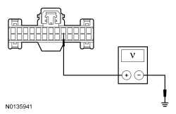
- Measure the voltage between
C2414A-5, circuit SBP23 (WH/RD), harness side and ground.
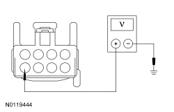
 - Measure the voltage between
C2414B-8, circuit SBP24 (VT/RD), harness side and ground.
 - Is the voltage greater than 10 volts?
| Yes
GO to
A3
.
No
VERIFY
fuses 23 (15A) and 24 (15A) are OK. If OK, REPAIR the affected circuit. If not OK, REFER to the Wiring Diagrams manual to identify the cause for the circuit short. TEST the system for normal operation.
|
|
A3 CHECK THE SCCM GROUND CIRCUIT FOR AN OPEN
|
|
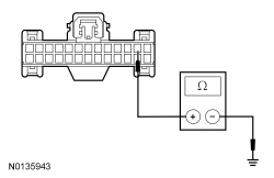
- Measure the resistance between
C2414A-2, circuit GD375 (BK/BU), harness side and ground.
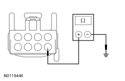
 - Measure the resistance between
C2414B-5, circuit GD375 (BK/BU), harness side and ground.
 - Are the resistances less than 5 ohms?
| Yes
GO to
A4
.
No
REPAIR the circuit. TEST the system for normal operation.
|
|
A4 CHECK THE STEERING COLUMN ADJUST SWITCH (STRCOL_ADJ) PID
|
|
- Connect:
C2414A.
- Connect:
C2414B.
- Ignition ON.
- Enter the following diagnostic mode on the scan tool: DataLogger —
.
- Monitor the
PID STRCOL_ADJ while moving the steering column control switch in all directions.
- Do the PID values agree with the steering column control switch positions?
| Yes
GO to
A5
.
No
INSTALL a new steering column control switch. REFER to
Section 211-05
.
CLEAR the DTCs. VERIFY correct system operation. REPEAT the self-test
If the concern is still present, INSTALL a new
. REFER to
Section 211-05
. TEST the system for normal operation.
|
|
A5 CHECK THE ADJUSTABLE STEERING COLUMN MOTOR CIRCUITS FOR A SHORT TO VOLTAGE
|
|
- Ignition OFF.
- Disconnect:
C2414A.
- Disconnect:
C2414B.
- Ignition ON.
- Measure the voltage between:
- C2414B-1, circuit CPP22 (GY/BN), harness side and ground.
- C2414B-2, circuit CPP04 (GY), harness side and ground.
- C2414B-7, circuit CPP05 (WH/VT), harness side and ground.
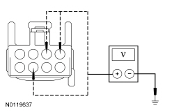 - Is any voltage present?
| Yes
REPAIR the affected circuit(s). TEST the system for normal operation.
No
GO to
A6
.
|
|
A6 CHECK THE ADJUSTABLE STEERING COLUMN MOTOR CIRCUITS FOR A SHORT TO GROUND
|
|
- Ignition OFF.
- Measure the resistance between:
- C2414B-1, circuit CPP22 (GY/BN), harness side and ground.
- C2414B-2, circuit CPP04 (GY), harness side and ground.
- C2414B-7, circuit CPP05 (WH/VT), harness side and ground.
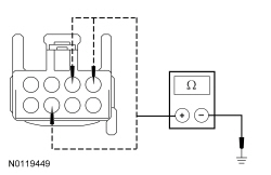 - Are the resistances greater than 10,000 ohms?
| Yes
GO to
A7
.
No
REPAIR the affected circuit(s). TEST the system for normal operation.
|
|
A7 CHECK THE ADJUSTABLE STEERING COLUMN MOTOR CIRCUITS FOR AN OPEN
|
|
- Disconnect: Adjustable Steering Column Tilt Motor C267 or Adjustable Steering Column Telescope Motor C227.
- For an inoperative adjustable steering column tilt motor, measure the resistance between
C2414B and adjustable steering column tilt motor C267 using the following chart:
| Circuit
| Adjustable Steering Column Tilt Motor
|
|---|
| C2414B-7
| CPP05 (WH/VT)
| C267-1
| | C2414B-2
| CPP04 (GY)
| C267-2
|
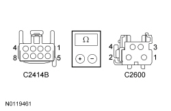 - For an inoperative adjustable steering column telescope motor, measure the resistance between
C2414B and adjustable steering column telescope motor C227 using the following chart:
| Circuit
| Adjustable Steering Column Telescope Motor
|
|---|
| C2414B-7
| CPP05 (WH/VT)
| C227-3
| | C2414B-1
| CPP22 (GY/BN)
| C227-1
|
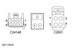 - Is the resistance less than 5 ohms?
| Yes
For a tilt motor that is inoperative/does not operate correctly, GO to
A8
.
For a telescope motor that is inoperative/does not operate correctly, GO to
A9
.
No
REPAIR the affected circuit(s). CLEAR the DTCs. REPEAT the self-test.
|
|
A8 CHECK THE SCCM OUTPUT TO THE ADJUSTABLE STEERING COLUMN TILT MOTOR
|
|
- Ignition OFF.
- Connect:
C2414A.
- Connect:
C2414B.
- NOTICE:
The following step uses a test light to simulate normal circuit loads. Use only the test light recommended in the Special Tools table at the beginning of this section. To avoid connector terminal damage, use the Flex Probe Kit for the test light probe connection to the vehicle. Do not use the test light probe directly on any connector.
- Connect a 12-volt incandescent test light between adjustable steering column tilt motor C267-1, circuit CPP05 (WH/VT), harness side and C267-2, circuit CPP04 (GY), harness side.
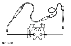 - Ignition ON.
- NOTE:
Because the steering column motor (Hall-effect sensor) is disconnected, the
only activates the output for approximately 1 second each time the steering column control switch is activated (jog mode).
- Activate the steering column control switch in both the UP and DOWN positions (release the switch briefly between each switch activation) while observing the test light.
- Does the test light momentarily illuminate when the steering column control switch is activated in both UP and DOWN positions?
| Yes
INSTALL a new adjustable steering column tilt motor. REFER to
Steering Column Motor
. TEST the system for normal operation.
No
GO to
A10
.
|
|
A9 CHECK THE SCCM OUTPUT TO THE ADJUSTABLE STEERING COLUMN TELESCOPE MOTOR
|
|
- Ignition OFF.
- Connect:
C2414A.
- Connect:
C2414B.
- NOTICE:
The following step uses a test light to simulate normal circuit loads. Use only the test light recommended in the Special Tools table at the beginning of this section. To avoid connector terminal damage, use the Flex Probe Kit for the test light probe connection to the vehicle. Do not use the test light probe directly on any connector.
- Connect a 12-volt incandescent test light between adjustable steering column telescope motor C227-3, circuit CPP05 (WH/VT), harness side and C227-1, circuit CPP22 (GY/BN), harness side.
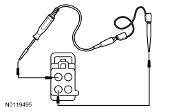 - Ignition ON.
- NOTE:
Because the steering column motor (Hall-effect sensor) is disconnected, the
only activates the output for approximately 1 second each time the steering column control switch is activated (jog mode).
- Activate the steering column control switch in both the FORWARD and REARWARD positions (release the switch briefly between each switch activation) while observing the test light.
- Does the test light momentarily illuminate when the steering column control switch is activated in both FORWARD and REARWARD positions?
| Yes
INSTALL a new steering column assembly. REFER to
Steering Column
. TEST the system for normal operation.
No
GO to
A10
.
|
|
A10 CHECK FOR CORRECT SCCM OPERATION
|
|
- Disconnect and inspect all
connectors.
- Repair:
- corrosion (install new connector or terminals – clean module pins)
- damaged or bent pins – install new terminals/pins
- pushed-out pins – install new pins as necessary
- Reconnect the
connectors. Make sure they seat and latch correctly.
- Operate the system and determine if the concern is still present.
- Is the concern still present?
| Yes
CHECK
for any applicable TSBs. If a TSB exists for this concern, DISCONTINUE this test and FOLLOW TSB instructions. If no TSBs address this concern, INSTALL a new
. REFER to
Section 211-05
.
No
The system is operating correctly at this time. The concern may have been caused by module connections. ADDRESS the root cause of any connector or pin issues.
|
Pinpoint Test B: The Adjustable Steering Column is Inoperative in One or More Directions — Using the Memory SET Switch Buttons/Using an RKE Transmitter/Using the Easy Entry/Exit Feature
Refer to Wiring Diagrams Cell
128
, Adjustable Steering Column for schematic and connector information.
Normal Operation
When the desired memory position is selected using the memory SET switch or an
transmitter, the
communicates the desired steering column position in a message on the
to the
. The
acts as a gateway module, relaying the message to the
over the
. The
monitors the position of the adjustable steering column using Hall-effect type rotation sensors that are integral to the tilt and telescoping motors. The sensors provide a digital signal used by the
to calculate the position of the steering column in relation to the full forward/rearward and full up/down positions. The
uses these signals to store and recall memory positions, carry out easy entry/exit operations and to make sure the tilt and telescope motors do not stall against the steering column end of travel. If a tilt or telescope motor sensor DTC sets, the
does not recall a programmed memory position or automatically position the steering column during the easy entry/exit operation. If a DTC sets for either sensor, the affected adjustable steering column motor operates in jog mode. Jog mode allows limited operation of the affected steering column motor using only the steering column control switch. When the steering column control switch is operated in jog mode, the steering column moves in the desired direction for one second, then stops. The steering column control switch must be released, then pressed again in order to move the steering column for an additional second.
Possible Sources:
- Entry/exit feature is disabled in the message center
- Wiring, terminals or connectors
- Memory SET switch
- transmitter
PINPOINT TEST B: THE ADJUSTABLE STEERING COLUMN IS INOPERATIVE IN ONE OR MORE DIRECTIONS — USING THE MEMORY SET SWITCH BUTTONS/USING AN RKE TRANSMITTER/USING THE EASY ENTRY/EXIT FEATURE
NOTICE:
Use the Flex Probe Kit for all test connections to prevent damage to the wiring terminals. Do not use standard multi-meter probes.
| Test Step
| Result / Action to Take
|
|---|
|
B1 CHECK THE OPERATION OF THE ADJUSTABLE COLUMN USING THE STEERING COLUMN CONTROL SWITCH
|
|
- Operate the adjustable steering column in all directions using the steering column control switch.
- Does the steering column move for more than one second in each direction using the steering column control switch?
| Yes
If the adjustable steering column is inoperative using the easy entry/exit feature, GO to
B2
.
If the adjustable steering column is inoperative using the memory SET switch, GO to
B3
.
If the adjustable steering column is inoperative using an
transmitter, GO to
B4
.
No
If the steering column does not move at all in one or more directions using the steering column switch,
GO to Pinpoint Test A
.
If the steering column only moves in one second intervals (jog mode) in one or more directions using the steering column switch,
GO to Pinpoint Test C
.
|
|
B2 VERIFY THE EASY ENTRY/EXIT FEATURE IS ENABLED
|
|
- Verify the easy entry/exit feature is enabled using the message center. Refer to the Owner's Literature for additional instructions for using the message center.
- Does the message center indicate that the easy entry/exit feature is enabled?
| Yes
GO to
B5
.
No
TOGGLE the easy entry/exit feature on using the message center controls. TEST the system for normal operation.
|
|
B3 CHECK THE OPERATION OF THE MEMORY SEATS, MEMORY MIRRORS AND STEERING COLUMN USING THE MEMORY SET SWITCH
|
|
- Check the operation of the seats, memory mirrors and steering column using the memory SET switch. Refer to the Owner's Literature for additional instructions for programming a memory position.
- Do the seats and mirrors operate properly using the memory SET switch?
| Yes
If only the adjustable steering column is inoperative using the memory SET switch, GO to
B5
.
No
If the seats and mirrors are also inoperative using the memory SET switch, REFER to
Section 501-10
.
|
|
B4 CHECK THE OPERATION OF THE MEMORY SEATS, MIRRORS AND STEERING COLUMN USING AN RKE TRANSMITTER
|
|
- Check the operation of the seats, mirrors and steering column using an
transmitter. Refer to the Owner's Literature for additional instructions for programming a memory position to an
transmitter.
- Do the seats and mirrors operate properly using an
transmitter?
| Yes
If only the adjustable steering column is inoperative using an
transmitter, GO to
B5
.
No
If the seats and mirrors are also inoperative using an
transmitter, REFER to
Section 501-10
.
|
|
B5 CHECK FOR
,
OR
DTCs
|
|
- Ignition ON.
- Enter the following diagnostic mode on the scan tool: Self Test —
.
- Enter the following diagnostic mode on the scan tool: Self Test —
.
- Enter the following diagnostic mode on the scan tool: Self-Test —
.
- Record any DTCs retrieved from the
,
and
.
- Are any symptom or communication related DTCs present?
| Yes
To diagnose the
DTCs, REFER to
Section 501-10
.
To diagnose the
DTCs, REFER to
Section 419-10
.
To diagnose the
DTCs, REFER to
Section 211-05
.
No
GO to
B6
.
|
|
B6 CHECK FOR CORRECT SCCM OPERATION
|
|
- Disconnect and inspect all
connectors.
- Repair:
- corrosion (install new connector or terminals – clean module pins)
- damaged or bent pins – install new terminals/pins
- pushed-out pins – install new pins as necessary
- Reconnect the
connectors. Make sure they seat and latch correctly.
- Operate the system and determine if the concern is still present.
- Is the concern still present?
| Yes
CHECK
for any applicable TSBs. If a TSB exists for this concern, DISCONTINUE this test and FOLLOW TSB instructions. If no TSBs address this concern, INSTALL a new
. REFER to
Section 211-05
.
No
The system is operating correctly at this time. The concern may have been caused by module connections. ADDRESS the root cause of any connector or pin issues.
|
Pinpoint Test C: The Adjustable Steering Column Operates in One Second Intervals When Using the Steering Column Control Switch (Jog Mode)
Refer to Wiring Diagrams Cell
128
, Adjustable Steering Column for schematic and connector information.
Normal Operation
The
monitors the position of the adjustable steering column using of Hall-effect type rotation sensors that are integral to the tilt and telescoping motors. The adjustable steering column tilt motor is serviced separately from the steering column. The adjustable steering column telescope motor is not serviceable. If a new adjustable steering column telescope motor sensor is needed, install a new steering column assembly.
The
sends a reference voltage along the sensor feed circuit through the Hall-effect sensor and back to the
through a shared signal return circuit. The sensors provide a digital signal used by the
to calculate the position of the steering column in relation to the full forward/rearward and full up/down positions. The
uses this signal to store and recall memory positions, to carry out the easy entry/exit operations and to make sure the adjustable steering column tilt and telescope motors do not stall against the steering column end of travel.
If an adjustable steering column tilt or telescope motor sensor DTC sets (or if either of the sensor circuits become open), the
does not recall a programmed memory position or automatically position the steering column during the easy entry/exit operations. The affected steering column motor operates in jog mode. Jog mode allows limited operation of the affected steering column motor using only the steering column control switch. When the steering column control switch is operated in jog mode, the steering column moves in the desired direction for one second, then stops regardless of the length of time the switch is actually activated. The steering column control switch must be released, then activated again in order to move the steering column for an additional second.
| DTC
| DTC Description
| Fault Trigger Conditions
|
| B1C33:11
| Steering Column Tilt Feedback Signal: Circuit Short To Ground
| This DTC sets when the
senses the adjustable steering column tilt motor feedback sensor signal is below 1.5 volts. This may be caused by a short to ground in the sensor signal circuit.
|
| B1C33:12
| Steering Column Tilt Feedback Signal: Circuit Short To Battery
| This DTC sets when the
senses the adjustable steering column tilt motor feedback sensor signal is above 7 volts. This may be caused by a short to voltage in the sensor signal circuit.
|
| B1C35:11
| Steering Column Telescope Feedback Signal: Circuit Short To Ground
| This DTC sets when the
senses the adjustable steering column telescope motor feedback sensor signal is below 1.5 volts. This may be caused by a short to ground in the sensor signal circuit.
|
| B1C35:12
| Steering Column Telescope Feedback Signal: Circuit Short To Battery
| This DTC sets when the
senses the adjustable steering column telescope motor feedback sensor signal is above 7 volts. This may be caused by a short to voltage in the sensor signal circuit.
|
Possible Sources:
- Wiring, terminals or connectors
- Adjustable steering column tilt motor
- Steering column assembly
PINPOINT TEST C: THE ADJUSTABLE STEERING COLUMN OPERATES IN ONE SECOND INTERVALS WHEN USING THE STEERING COLUMN CONTROL SWITCH (JOG MODE)
NOTICE:
Use the Flex Probe Kit for all test connections to prevent damage to the wiring terminals. Do not use standard multi-meter probes.
| Test Step
| Result / Action to Take
|
|---|
|
C1 CHECK THE TILT/TELESCOPE SENSOR CIRCUITS FOR A SHORT TO VOLTAGE
|
|
- Ignition OFF.
- Disconnect:
C2414A.
- Disconnect: Adjustable Steering Column Tilt Motor C267.
- Disconnect: Adjustable Steering Column Telescope Motor C227.
- Ignition ON.
- Measure the voltage between:
- C2414A-22, circuit RPP06 (GN), harness side and ground.
- C2414A-25, circuit VPP08 (WH), harness side and ground.
- C2414A-24, circuit VPP17 (VT/BN), harness side and ground.
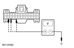 - Is any voltage present?
| Yes
REPAIR the affected circuit(s). TEST the system for normal operation.
No
GO to
C2
.
|
|
C2 CHECK THE TILT/TELESCOPE SENSOR CIRCUITS FOR A SHORT TO GROUND
|
|
- Ignition OFF.
- Measure the resistance between:
- C2414A-22, circuit RPP06 (GN), harness side and ground.
- C2414A-25, circuit VPP08 (WH), harness side and ground.
- C2414A-24, circuit VPP17 (VT/BN), harness side and ground.
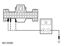 - Is the resistance greater than 10,000 ohms?
| Yes
GO to
C3
.
No
REPAIR the affected circuit(s). TEST the system for normal operation.
|
|
C3 CHECK THE TILT/TELESCOPE SENSOR CIRCUITS FOR A SHORT TOGETHER
|
|
- Measure the resistance between
C2414A-25, circuit VPP08 (WH), harness side and
C2414A-24, circuit VPP17 (VT/BN), harness side.
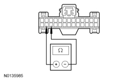 - Is the resistance greater than 10,000 ohms?
| Yes
GO to
C4
.
No
REPAIR the affected circuit(s). TEST the system for normal operation.
|
|
C4 CHECK THE TILT/TELESCOPE SENSOR CIRCUITS FOR AN OPEN
|
|
- Measure the resistance between
C2414A, harness side and adjustable steering column tilt motor C267; and between
C2414A, harness side and adjustable steering column telescope motor C227, harness side using the following chart:
| Circuit
| Adjustable Steering Column Tilt/Telescope Motor
|
|---|
| C2414A-22
| RPP06 (GN)
| C267-3
| | C2414A-22
| RPP06 (GN)
| C227-4
| | C2414A-25
| VPP08 (WH)
| C267-4
| | C2414A-24
| VPP17 (VT/BN)
| C227-2
|
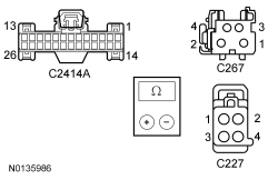 - Are the resistances less than 5 ohms?
| Yes
GO to
C5
.
No
REPAIR the affected circuit(s). TEST the system for normal operation.
|
|
C5 CHECK FOR CORRECT SCCM OPERATION
|
|
- Disconnect and inspect all
connectors.
- Repair:
- corrosion (install new connector or terminals – clean module pins)
- damaged or bent pins – install new terminals/pins
- pushed-out pins – install new pins as necessary
- Reconnect the
connectors. Make sure they seat and latch correctly.
- Operate the system and determine if the concern is still present.
- Is the concern still present?
| Yes
CHECK
for any applicable TSBs. If a TSB exists for this concern, DISCONTINUE this test and FOLLOW TSB instructions. If no TSBs address this concern, PROCEED to the following:
If the adjustable steering column does not operate correctly when the steering column control switch is in the UP/DOWN (tilt) position(s), INSTALL a new adjustable steering column tilt motor. REFER to
Steering Column Motor
. CLEAR the DTCs. REPEAT the self-test. If the concern is still present, INSTALL a new
. REFER to
Section 211-05
.
If the adjustable steering column does not operate correctly when the steering column control switch is in the FORWARD/REARWARD (telescope) position(s), INSTALL a new steering column assembly. REFER to
Steering Column
. CLEAR the DTCs. REPEAT the self-test. If the concern is still present, INSTALL a new
. REFER to
Section 211-05
.
No
The system is operating correctly at this time. The concern may have been caused by module connections. ADDRESS the root cause of any connector or pin issues.
|


