SECTION 413-06: Horn
2014 Flex Workshop Manual
DIAGNOSIS AND TESTING
Procedure revision date: 05/02/2013

Horn


Symptom Chart

Diagnostics in this manual assume a certain skill level and knowledge of Ford-specific diagnostic practices. Refer to Diagnostic Methods in Section 100-00 for information about these practices.

 
Symptom Chart
Condition Possible Sources Action
  • The horn is inoperative
  • Refer to the Diagnostic Routine
  • The horn is always on
  • Refer to the Diagnostic Routine
 

Pinpoint Tests


Pinpoint Test A: The Horn Is Inoperative

Diagnostic Overview

Diagnostics in this manual assume a certain skill level and knowledge of Ford-specific diagnostic practices. Refer to Diagnostic Methods in Section 100-00 for information about these practices.

Refer to Wiring Diagrams Cell 44 , Horn/Cigar Lighter for schematic and connector information.

Normal Operation and Fault Conditions

REFER to Horn .

Visual Inspection and Diagnostic Pre-checks

Inspect the BCM fuse 22 (20A).

 
PINPOINT TEST A: THE HORN IS INOPERATIVE
Test Step Result / Action to Take
  A1 CHECK THE BCM OUTPUT  
  • Ignition ON.
  • Enter the following diagnostic mode on the scan tool: DataLogger — BCM .
  • Command the HORN active command ON and then OFF.
  • Does the horn sound when commanded on?
Yes
GO to A2 .

No
VERIFY the BCM fuse 22 (20A) is OK. If OK, GO to A8 .
  A2 CHECK FOR VOLTAGE TO THE SCCM  
  • Ignition OFF.
  • Remove the steering column shrouds. Refer to Section 211-04 .
  • Disconnect: SCCM C2414A.
  • Measure the voltage between:


  • Positive Lead Negative Lead
    Pin Circuit Pin Circuit
    C2414A-9 CRH04 (VT/GN) Ground


  • Is the voltage greater than 11 volts?
Yes
GO to A4 .

No
GO to A3 .
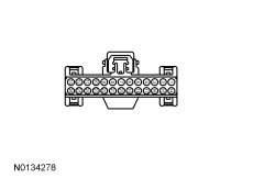
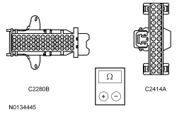
  A3 CHECK THE HORN RELAY COIL GROUND CONTROLLED CIRCUIT FOR AN OPEN  
  • Disconnect: BCM C2280B.
  • Measure the resistance between:


  • Positive Lead Negative Lead
    Pin Circuit Pin Circuit
    C2280B-33 CRH04 (VT/GN) C2414A-9 CRH04 (VT/GN)


  • Is the resistance less than 3 ohms?
Yes
GO to A11 .

No
REPAIR the circuit.
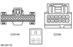
  A4 CHECK THE CLOCKSPRING GROUND CIRCUIT FOR AN OPEN  
  • Disconnect: Clockspring C218A.
  • Measure the resistance between:


  • Positive Lead Negative Lead
    Pin Circuit Pin Circuit
    C2414A-9 CRH04 (VT/GN) C218A-8 GD375 (BK/BU)


  • Is the resistance less than 3 ohms?
Yes
GO to A5 .

No
REPAIR the circuit.
  A5 ISOLATE THE STEERING WHEEL HARNESS  
  • Connect: Clockspring C218A.
  • Remove the driver air bag module. REFER to Section 501-20B .
  • Disconnect: Clockspring C218B.
  • Connect: Battery Ground Cable.
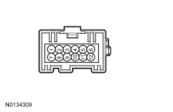
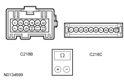
  • Measure the component side voltage between:


  • Positive Lead Negative Lead
    Pin Circuit Pin Circuit
    C218B-4 C218B-10


  • Is the voltage greater than 11 volts?
Yes
REPAIR the steering wheel harness for an open circuit or INSTALL a new steering wheel. REFER to Section 211-04 .

No
GO to A6 .
  A6 CHECK FOR VOLTAGE THROUGH THE CLOCKSPRING  
  • Measure the component side voltage between:


  • Positive Lead Negative Lead
    Pin Circuit Pin Circuit
    C218B-4 Ground


  • Is the voltage greater than 11 volts?
Yes
INSTALL a new clockspring. REFER to Section 501-20B .

No
GO to A7 .
  A7 CHECK FOR AN OPEN IN THE CLOCKSPRING  
  • Remove the clockspring. REFER to Section 501-20B .
  • Measure the component side resistance between:


  • Positive Lead Negative Lead
    Pin Circuit Pin Circuit
    C218B-4 C218C-1


  • Is the resistance less than 3 ohms?
Yes
GO to A12 .

No
INSTALL a new clockspring. REFER to Section 501-20B .
  A8 CHECK FOR VOLTAGE AND GROUND TO THE HORN  
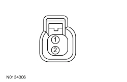
  • Disconnect: Horn C131.
  • While activating the horn, measure the voltage between:


  • Positive Lead Negative Lead
    Pin Circuit Pin Circuit
    C131-2 SRH01 (YE/RD) C131-1 GD123 (BK/GY)


  • Is the voltage greater than 11 volts?
Yes
INSTALL a new horn. REFER to Horn .

No
GO to A9 .
  A9 CHECK FOR VOLTAGE TO THE HORN  
  • While activating the horn, measure the voltage between:


  • Positive Lead Negative Lead
    Pin Circuit Pin Circuit
    C131-2 SRH01 (YE/RD) Ground


  • Is the voltage greater than 11 volts?
Yes
REPAIR the horn ground circuit for an open.

No
GO to A10 .
  A10 CHECK THE BCM HORN OUTPUT CIRCUIT FOR AN OPEN  
  • Ignition OFF.
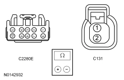
  • Disconnect: BCM C2280E.
  • Measure the resistance between:


  • Positive Lead Negative Lead
    Pin Circuit Pin Circuit
    C2280E-3 SRH01 (YE/RD) C131-2 SRH01 (YE/RD)


  • Is the resistance less than 3 ohms?
Yes
GO to A11 .

No
REPAIR the circuit.
  A11 CHECK FOR CORRECT BCM OPERATION  
  • Disconnect and inspect all BCM connectors.
  • Repair:
    • corrosion (install new connector or terminals – clean module pins)
    • damaged or bent pins – install new terminals/pins
    • pushed-out pins – install new pins as necessary
  • Reconnect the BCM connectors. Make sure they seat and latch correctly.
  • Operate the system and determine if the concern is still present.
  • Is the concern still present?
Yes
CHECK OASIS for any applicable TSBs. If a TSB exists for this concern, DISCONTINUE this test and FOLLOW TSB instructions. If no TSBs address this concern, INSTALL a new BCM . REFER to Section 419-10 .

No
The system is operating correctly at this time. The concern may have been caused by module connections. ADDRESS the root cause of any connector or pin issues.
  A12 CHECK FOR CORRECT SCCM OPERATION  
  • Disconnect and inspect all SCCM connectors.
  • Repair:
    • corrosion (install new connector or terminals – clean module pins)
    • damaged or bent pins – install new terminals/pins
    • pushed-out pins – install new pins as necessary
  • Reconnect the SCCM connectors. Make sure they seat and latch correctly.
  • Operate the system and determine if the concern is still present.
  • Is the concern still present?
Yes
CHECK OASIS for any applicable TSBs. If a TSB exists for this concern, DISCONTINUE this test and FOLLOW TSB instructions. If no TSBs address this concern, INSTALL a new SCCM . REFER to Section 211-05 .

No
The system is operating correctly at this time. The concern may have been caused by module connections. ADDRESS the root cause of any connector or pin issues.
 

Pinpoint Test B: The Horn Is Always On

Diagnostic Overview

Diagnostics in this manual assume a certain skill level and knowledge of Ford-specific diagnostic practices. Refer to Diagnostic Methods in Section 100-00 for information about these practices.

Refer to Wiring Diagrams Cell 44 , Horn/Cigar Lighter for schematic and connector information.

Normal Operation and Fault Conditions

REFER to Horn .

 
PINPOINT TEST B: THE HORN IS ALWAYS ON
Test Step Result / Action to Take
  B1 CHECK THE BCM HORN OUTPUT CIRCUIT FOR A SHORT TO VOLTAGE  
  • Ignition OFF.
  • Disconnect: BCM C2280E.
  • Ignition ON.
  • Does the horn continue to sound?
Yes
REPAIR the circuit.

No
GO to B2 .
  B2 ISOLATE THE BCM  
  • Ignition OFF.
  • Connect: BCM C2280E.
  • Disconnect: BCM C2280B.
  • Does the horn continue to sound?
Yes
GO to B6 .

No
GO to B3 .
  B3 CHECK THE HORN SWITCH INPUT TO THE BCM CIRCUIT FOR A SHORT TO GROUND  
  • Disconnect: SCCM C2414A.
  • Connect: BCM C2280B.
  • Does the horn continue to sound?
Yes
REPAIR the circuit.

No
GO to B4 .
  B4 ISOLATE THE STEERING WHEEL AND HARNESS  
  • Connect: SCCM C2414A.
  • Remove the driver air bag module. REFER to Section 501-20B .
  • Disconnect: Clockspring C218B.
  • Connect: Battery Ground Cable.
  • Does the horn continue to sound?
Yes
GO to B5 .

No
REPAIR the steering wheel harness for a short to ground or INSTALL a new steering wheel. REFER to Section 211-04 .
  B5 CHECK THE CLOCKSPRING FOR A SHORT TO GROUND  
  • Remove the clockspring. REFER to Section 501-20B .
  • Does the horn continue to sound?
Yes
GO to B7 .

No
INSTALL a new clockspring. REFER to Section 501-20B .
  B6 CHECK FOR CORRECT BCM OPERATION  
  • Disconnect and inspect all BCM connectors.
  • Repair:
    • corrosion (install new connector or terminals – clean module pins)
    • damaged or bent pins – install new terminals/pins
    • pushed-out pins – install new pins as necessary
  • Reconnect the BCM connectors. Make sure they seat and latch correctly.
  • Operate the system and determine if the concern is still present.
  • Is the concern still present?
Yes
CHECK OASIS for any applicable TSBs. If a TSB exists for this concern, DISCONTINUE this test and FOLLOW TSB instructions. If no TSBs address this concern, INSTALL a new BCM . REFER to Section 419-10 .

No
The system is operating correctly at this time. The concern may have been caused by module connections. ADDRESS the root cause of any connector or pin issues.
  B7 CHECK FOR CORRECT SCCM OPERATION  
  • Disconnect and inspect all SCCM connectors.
  • Repair:
    • corrosion (install new connector or terminals – clean module pins)
    • damaged or bent pins – install new terminals/pins
    • pushed-out pins – install new pins as necessary
  • Reconnect the SCCM connectors. Make sure they seat and latch correctly.
  • Operate the system and determine if the concern is still present.
  • Is the concern still present?
Yes
CHECK OASIS for any applicable TSBs. If a TSB exists for this concern, DISCONTINUE this test and FOLLOW TSB instructions. If no TSBs address this concern, INSTALL a new SCCM . REFER to Section 211-05 .

No
The system is operating correctly at this time. The concern may have been caused by module connections. ADDRESS the root cause of any connector or pin issues.