| DTC
| Description
| Action
|
|---|
| B108A:12
| Start Button: Circuit Short To Battery
| REFER to
Section 211-05
.
|
| B10AB:06
| Remote Keyless Entry Synchronization: Algorithm Based Failure
| REFER to
Section 501-14B
.
|
| B10C6:01
| Exterior Trunk Antenna: General Electrical Failure
| REFER to
Section 501-14B
.
|
| B10C7:01
| Interior Trunk Antenna: General Electrical Failure
| REFER to
Section 419-01C
.
|
| B10C8:01
| Interior Centre Antenna: General Electrical Failure
| REFER to
Section 419-01C
.
|
| B10C9:01
| Interior Front Antenna: General Electrical Failure
| REFER to
Section 419-01C
.
|
| B10D7:05
| PATS Key: System Programming Failure
| REFER to
Section 419-01C
.
|
| B10D7:31
| PATS Key: No Signal
| REFER to
Section 419-01C
.
|
| B10D8:51
| PATS Key Less Than Minimum Programmed: Not Programmed
| REFER to
Section 419-01C
.
|
| B10D9:11
| PATS Transponder: Circuit Short To Ground
| REFER to
Section 419-01C
.
|
| B10D9:12
| PATS Transponder: Circuit Short To Battery
| REFER to
Section 419-01C
.
|
| B10D9:31
| PATS Transponder: No Signal
| REFER to
Section 419-01C
.
|
| B10D9:87
| PATS Transponder: Missing Message
| REFER to
Section 419-01C
.
|
| B10DA:51
| PATS Target Identifier: Not Programmed
| REFER to
Section 419-01C
.
|
| B10DA:61
| PATS Target Identifier: Signal Calculation Failure
| REFER to
Section 419-01C
.
|
| B113E:11
| External Boot/Trunk Release Switch: Circuit Short To Ground
| REFER to
Section 501-14B
.
|
| B11C6:01
| Passenger Door External Antenna: General Electrical Failure
| REFER to
Section 501-14B
.
|
| B11CA:01
| Driver Door External Antenna: General Electrical Failure
| REFER to
Section 501-14B
.
|
| B121A:11
| Keypad Illumination Output: Circuit Short To Ground
| REFER to
Section 501-14B
.
|
| B121A:15
| Keypad Illumination Output: Circuit Short To Battery or Open
| REFER to
Section 501-14B
.
|
| B121B:11
| Keypad Input Switch: Circuit Short To Ground
| REFER to
Section 501-14B
.
|
| B1381:11
| Left Front Door Handle Proximity Sensor: Circuit Short To Ground
| REFER to
Section 501-14B
.
|
| B1381:15
| Left Front Door Handle Proximity Sensor: Circuit Short To Battery or Open
| REFER to
Section 501-14B
.
|
| B1381:29
| Left Front Door Handle Proximity Sensor : Signal Invalid
| REFER to
Section 501-14B
.
|
| B1382:11
| Right Front Door Handle Proximity Sensor: Circuit Short To Ground
| REFER to
Section 501-14B
.
|
| B1382:15
| Right Front Door Handle Proximity Sensor: Circuit Short To Battery or Open
| REFER to
Section 501-14B
.
|
| B1382:29
| Right Front Door Handle Proximity Sensor: Signal Invalid
| REFER to
Section 501-14B
.
|
| P1571:12
| Brake Switch: Circuit Short To Battery
| REFER to
Section 417-01
.
|
| U0140:87
| Lost Communication With Body Control Module: Missing Message
| GO to Pinpoint Test I
.
|
| U1000:00
| Solid State Driver Protection Active - Driver Disabled: No Sub Type Information
| GO to Pinpoint Test J
.
|
| U201F:31
| External Receiver: No Signal
| REFER to
Section 501-14B
.
|
| U201F:56
| External Receiver: Invalid/Incompatible Configuration
| CARRY OUT
on the
module. REFER to
Section 418-01
. CLEAR the DTCs. REPEAT the self-test. If DTC U201F:56 is retrieved again, INSTALL a new
module. REFER to
Remote Function Actuator (RFA) Module
.
|
| U2100:55
| Initial Configuration Not Complete: Not Configured
| CARRY OUT
on the
module. REFER to
Section 418-01
. CLEAR the DTCs. REPEAT the self-test. If DTC U2100:55 is retrieved again, INSTALL a new
module. REFER to
Remote Function Actuator (RFA) Module
.
|
| U3000:49
| Control Module: Internal Electronic Failure
| DIAGNOSE all other DTCs first. If no other DTCs are present, INSTALL a new
module. REFER to
Remote Function Actuator (RFA) Module
.
|
| U3003:62
| Battery Voltage: Signal Compare Failure
| GO to Pinpoint Test K
.
|
Diagnostics in this manual assume a certain skill level and knowledge of Ford-specific diagnostic practices. Refer to Diagnostic Methods in
Section 100-00
for information about these practices.
| Test Step
| Result / Action to Take
|
|---|
|
I1 VERIFY THE CUSTOMER CONCERN
|
|
- Ignition ON.
- Verify there is an observable symptom present.
- Is an observable symptom present?
| Yes
GO to
I2
.
No
The system is operating normally at this time. The DTC may have been set due to high network traffic or an intermittent fault condition.
|
|
I2 CHECK THE COMMUNICATION NETWORK
|
|
- Ignition ON.
- Using a scan tool, perform the network test.
- Does the
pass the network test?
| Yes
GO to
I3
.
No
REFER to
Section 418-00
, The
Does Not Respond To The Scan Tool.
|
|
I3 RETRIEVE THE RECORDED DTCs FROM THE
MODULE SELF-TEST
|
|
- Using a scan tool, perform the
module self-test.
- Is DTC U3003:62 recorded?
| Yes
GO to Pinpoint Test K
.
No
GO to
I4
.
|
|
I4 RETRIEVE THE RECORDED DTCs FROM THE
SELF-TEST
|
|
- Using a scan tool, perform the
self-test.
- Is DTC U3003:16 or DTC U3003:17 recorded?
| Yes
For DTC U3003:16,
GO to Pinpoint Test G
.
For DTC U3003:17,
GO to Pinpoint Test H
.
No
GO to
I5
.
|
|
I5 RECHECK THE
MODULE DTCs
|
|
NOTE:
If new modules were installed prior to the DTC being set, the module configuration may be incorrectly set during
or the
may not have been carried out.
- Using a scan tool, clear the DTCs. Repeat the
module self-test.
- Is DTC U0140:87 still present?
| Yes
GO to
I6
.
No
The system is operating correctly at this time. The DTC may have been set due to high network traffic or an intermittent fault condition.
|
|
I6 CHECK FOR DTC U0140:87 SET IN OTHER MODULES
|
|
- Ignition OFF.
- Ignition ON.
- Using a scan tool, clear the DTCs. Repeat the
self-test.
- Is DTC U0140:87 set in any other module?
| Yes
INSTALL a new
. REFER to
Body Control Module (BCM)
.
No
INSTALL a new
module. REFER to
Remote Function Actuator (RFA) Module
.
|
Diagnostics in this manual assume a certain skill level and knowledge of Ford-specific diagnostic practices. Refer to Diagnostic Methods in
Section 100-00
for information about these practices.
Diagnostics in this manual assume a certain skill level and knowledge of Ford-specific diagnostic practices. Refer to Diagnostic Methods in
Section 100-00
for information about these practices.
| Test Step
| Result / Action to Take
|
|---|
|
K1 RECHECK THE
MODULE DTCs
|
|
- Ignition OFF.
- Ignition ON.
- Using a scan tool, clear the DTCs. Repeat the
module self-test.
- Is DTC U3003:62 still present?
| Yes
GO to
K2
.
No
The system is operating normally at this time. The DTC may have been set due to a previous low battery voltage condition, during battery charging or while jump starting the vehicle.
|
|
K2 CHECK FOR CHARGING SYSTEM DTCs IN THE PCM
|
|
- Using a scan tool, perform the PCM
self-test.
- Are any charging system DTCs set in the PCM?
| Yes
REFER to
Section 414-00
.
No
GO to
K3
.
|
|
K3 CHECK FOR DTCs B1317, B1318, B1676, P0563, U3003:16 OR U3003:17 SET IN OTHER MODULES
|
|
- Using a scan tool, retrieve the continuous memory DTCs from all modules.
- Is DTC B1317, B1318, B1676, P0563 (PCM), U3003:16 or U3003:17 set in any other module?
| Yes
REFER to
Section 414-00
: to diagnose the charging system condition.
No
GO to
K4
.
|
|
K4 CHECK THE BATTERY VOLTAGE
|
|
- Turn off all interior/exterior lights and accessories.
- Start and run the engine at approximately 2,000 RPM for 3 minutes while monitoring the battery voltage.
- Does the battery voltage rise to 15 volts or higher?
| Yes
REFER to
Section 414-00
: Charging System to diagnose the charging system condition.
No
GO to
K5
.
|
|
K5 CHECK THE BATTERY CONDITION AND STATE OF CHARGE
|
|
- Ignition OFF.
- Check the battery condition and verify the battery is fully charged. Refer to
Section 414-00
.
- Is the battery OK and fully charged?
| Yes
GO to
K6
.
No
REFER to
Section 414-00
.
|
|
K6 CHECK THE
MODULE VOLTAGE PID
|
|
- Ignition ON.
- Measure and record the voltage at the battery.
- Enter the following diagnostic mode on the scan tool:
Module DataLogger.
- Monitor the
module voltage PID (ECU_Pwr_Sup).
- Is the voltage within 0.2 volt of the recorded battery voltage?
| Yes
GO to
K9
.
No
GO to
K7
.
|
|
K7 CHECK THE
MODULE VOLTAGE SUPPLY
|
|
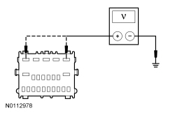
- Ignition OFF.
- Disconnect:
Module C2153C.
- Ignition ON.
- Measure the
voltage
between:
| Positive
| Lead
| Negative
| Lead
| | Pin
| Circuit
| Pin
| Circuit
| | C2153C-1
| SBP11 (BU/RD)
| —
| Ground
| | C2153C-5
| SBP27 (BU/RD)
| —
| Ground
|
 - Are the voltages within 0.2 volt of the recorded battery voltage?
| Yes
GO to
K8
.
No
REPAIR the circuit for high resistance as necessary. CLEAR the DTC.
|
|
K8 CHECK THE
MODULE GROUND CIRCUIT FOR HIGH RESISTANCE
|
|
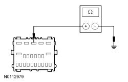
- Ignition OFF.
- Measure the
resistance
between:
| Positive
| Lead
| Negative
| Lead
| | Pin
| Circuit
| Pin
| Circuit
| | C2153C-3
| GD374 (BK/WH)
| —
| Ground
|
 - Is the resistance less than 3 ohms?
| Yes
GO to
K9
.
No
REPAIR the circuit for high resistance. CLEAR the DTC.
|
|
K9 CHECK FOR CORRECT
MODULE OPERATION
|
|
- Disconnect the
module connectors.
- Repair:
- corrosion (install new connector or terminals -clean module pins)
- damaged pins - install new terminals/pins
- pushed-out pins - install new pins as necessary
- Reconnect the
module connectors and make sure they seat and latch correctly.
- Operate the system and determine if the concern is still present.
- Is the concern still present?
| Yes
CHECK
for any applicable TSBs. If a TSB exists for this concern, discontinue this test and follow TSB instructions. If no TSBs address this concern, INSTALL a new
module. REFER to
Remote Function Actuator (RFA) Module
.
No
The system is operating correctly at this time. The concern may have been caused by module connections. ADDRESS the root cause of any connector or pin issues.
|

