
POM6411 or equivalent

105-00120

CCMSYNC-KIT
SECTION 415-00A: Information and Entertainment Systems — 4.2-Inch (107 mm) Screen, 6 Speakers
| 2014 Flex Workshop Manual
|
DIAGNOSIS AND TESTING
| Procedure revision date: 07/31/2013
|
 | Back-probe Pins
POM6411 or equivalent |
 | Multi-Media Interface Tester (MIT) (SYNC®)
105-00120 |
 | SYNC® RE-FLASH KIT
CCMSYNC-KIT |
Preliminary Inspection
Before diagnosing or repairing the audio system, verify the audio system module(s) pass the network test.
DTC Charts
NOTE: For SYNC® related concerns, REFER to the SYNC® Symptom Chart before connecting the scan tool and beginning DTC-based diagnostics.
Diagnostics in this manual assume a certain skill level and knowledge of Ford-specific diagnostic practices. Refer to Diagnostic Methods in Section 100-00 for information about these practices.
Audio Front Control Module (ACM) DTC Chart
| DTC | Description | Action |
|---|---|---|
| B1A01:01 | Speaker #1: General Electrical Failure | For LF door speaker,
GO to Pinpoint Test M
.
For LF A-pillar speaker, GO to Pinpoint Test K . |
| B1A01:11 | Speaker #1: Circuit Short To Ground | For LF door speaker,
GO to Pinpoint Test M
.
For LF A-pillar speaker, GO to Pinpoint Test K . |
| B1A01:12 | Speaker #1: Circuit Short To Battery | For LF door speaker,
GO to Pinpoint Test M
.
For LF A-pillar speaker, GO to Pinpoint Test K . |
| B1A01:13 | Speaker #1: Circuit Open | GO to Pinpoint Test M . |
| B1A02:01 | Speaker #2: General Electrical Failure | For RF door speaker,
GO to Pinpoint Test N
.
For RF A-pillar speaker, GO to Pinpoint Test L . |
| B1A02:11 | Speaker #2: Circuit Short To Ground | For RF door speaker,
GO to Pinpoint Test N
.
For RF A-pillar speaker, GO to Pinpoint Test L . |
| B1A02:12 | Speaker #2: Circuit Short To Battery | For RF door speaker,
GO to Pinpoint Test N
.
For RF A-pillar speaker, GO to Pinpoint Test L . |
| B1A02:13 | Speaker #2: Circuit Open | GO to Pinpoint Test N . |
| B1A03:01 | Speaker #3: General Electrical Failure | GO to Pinpoint Test P . |
| B1A03:11 | Speaker #3: Circuit Short To Ground | GO to Pinpoint Test P . |
| B1A03:12 | Speaker #3: Circuit Short To Battery | GO to Pinpoint Test P . |
| B1A03:13 | Speaker #3: Circuit Open | GO to Pinpoint Test P . |
| B1A04:01 | Speaker #4: General Electrical Failure | GO to Pinpoint Test O . |
| B1A04:11 | Speaker #4: Circuit Short To Ground | GO to Pinpoint Test O . |
| B1A04:12 | Speaker #4: Circuit Short To Battery | GO to Pinpoint Test O . |
| B1A04:13 | Speaker #4: Circuit Open | GO to Pinpoint Test O . |
| B1A56:21 | Antenna: Signal Amplitude | GO to Pinpoint Test A . |
| B1A89:11 | Satellite Antenna: Circuit Short To Ground | GO to Pinpoint Test B . |
| B1A89:13 | Satellite Antenna: Circuit Open | GO to Pinpoint Test B . |
| B1D19:49 | Compact Disc Unit: Internal Electronic Failure | CLEAR the DTCs. REPEAT the self-test. If DTC B1D19:49 is retrieved again, INSTALL a new ACM . REFER to Audio Control Module (ACM) . |
| B1D19:4B | Compact Disc Unit: Over Temperature | The ACM was over-temperature. This may occur during extended use. Audio operation can resume after the ACM cools. CLEAR the DTCs. This is normal operation. |
| U0155:00 | Lost Communication With Instrument Panel Cluster ( IPC ) Control Module: No Sub Type Information | GO to Pinpoint Test Z . |
| U0253:00 | Lost Communication With Accessory Protocol Interface Module: No Sub Type Information | GO to Pinpoint Test AB . |
| U0256:00 | Lost Communication With Front Controls Interface Module "A": No Sub Type Information | GO to Pinpoint Test AD . |
| U0257:00 | Lost Communication With Front Controls/Display Interface Module: No Sub Type Information | GO to Pinpoint Test AE . |
| U201A:51 | Control Module Main Calibration Data: Not Programmed | CHECK vehicle service history for recent service actions related to this module. This DTC sets due to incomplete or incorrect PMI procedures. If there have been recent service actions with this module, REPEAT/PERFORM the PMI procedure as directed by the scan tool. If there have been no recent service actions, INSTALL a new module to correct the failure to retain configuration data. REFER to Audio Control Module (ACM) . |
| U2100:00 | Initial Configuration Not Complete: No Sub Type Information | CHECK vehicle service history for recent service actions related to this module. This DTC sets due to incomplete or incorrect PMI procedures. If there have been recent service actions with this module, REPEAT/PERFORM the PMI procedure as directed by the scan tool. If there have been no recent service actions, INSTALL a new module to correct the failure to retain configuration data. REFER to Audio Control Module (ACM) . |
| U2101:00 | Control Module Configuration Incompatible: No Sub Type Information | CHECK vehicle service history for recent service actions related to this module. This DTC sets due to incomplete or incorrect PMI procedures. If there have been recent service actions with this module, REPEAT/PERFORM the PMI procedure as directed by the scan tool. If there have been no recent service actions, INSTALL a new module to correct the failure to retain configuration data. REFER to Audio Control Module (ACM) . |
| U3000:41 | Control Module: General Checksum Failure | CLEAR the DTCs. REPEAT the self-test. If DTC U3000:41 is retrieved again, INSTALL a new ACM . REFER to Audio Control Module (ACM) . |
| U3000:42 | Control Module: General Memory Failure | CLEAR the DTCs. REPEAT the self-test. If DTC U3000:42 is retrieved again, INSTALL a new ACM . REFER to Audio Control Module (ACM) . |
| U3000:96 | Control Module: Component Internal Failure | GO to Pinpoint Test B . |
| U3003:16 | Battery Voltage: Circuit Voltage Below Threshold | GO to Pinpoint Test AF . |
| U3003:17 | Battery Voltage: Circuit Voltage Above Threshold | GO to Pinpoint Test AG . |
Accessory Protocol Interface Module (APIM) DTC Chart
| DTC | Description | Action |
|---|---|---|
| B1252:04 | USB Port: System Internal Failure | GO to Pinpoint Test V . |
| B1252:11 | USB Port: Circuit Short to Ground | GO to Pinpoint Test V . |
| B12B8:04 | USB # 2 Port: System Internal Failure | NOTE: This DTC refers to USB port #2 on the APIM itself, which is not used. INSPECT the APIM USB port #2 for damage and remove any debris. CLEAR the DTCs. REPEAT the self-test. If DTC B12B8:04 is retrieved again, For diagnosing and testing please refer to the on-line Workshop Manual. If you do not have an on-line subscription, go to www.motorcraftservice.com. |
| B12B8:11 | USB # 2 Port: Circuit Short to Ground | NOTE: This DTC refers to USB port #2 on the APIM itself, which is not used. INSPECT the APIM USB port #2 for damage and remove any debris. CLEAR the DTCs. REPEAT the self-test. If DTC B12B8:11 is retrieved again, For diagnosing and testing please refer to the on-line Workshop Manual. If you do not have an on-line subscription, go to www.motorcraftservice.com. |
| B1D79:01 | Microphone Input: General Electrical Failure | GO to Pinpoint Test T . |
| B1D79:11 | Microphone Input: Circuit Short to Ground | GO to Pinpoint Test T . |
| B1D79:12 | Microphone Input: Circuit Short to Battery | GO to Pinpoint Test T . |
| B1D79:13 | Microphone Input: Circuit Open | GO to Pinpoint Test T . |
| U0140:00 | Lost Communication With Body Control Module: No Sub Type Information | GO to Pinpoint Test Y . |
| U0155:00 | Lost Communication With Instrument Panel Cluster ( IPC ) Control Module: No Sub Type Information | GO to Pinpoint Test Z . |
| U0257:00 | Lost Communication With Front Controls/Display Interface Module: No Sub Type Information | GO to Pinpoint Test AE . |
| U0423:00 | Invalid Data Received From Instrument Panel Control Module: No Sub Type Information | REFER to Section 413-01 , to retrieve and follow DTCs present in the IPC . |
| U2100:00 | Initial Configuration Not Complete: No Sub Type Information | CHECK vehicle service history for recent service actions related to this module. This DTC sets due to incomplete or incorrect PMI procedures. If there have been recent service actions with this module, REPEAT/PERFORM the APIM programming as directed by the scan tool. REFER to Accessory Protocol Interface Module (APIM) Programming . If there have been no recent service actions, For diagnosing and testing please refer to the on-line Workshop Manual. If you do not have an on-line subscription, go to www.motorcraftservice.com. |
| U2101:00 | Control Module Configuration Incompatible: No Sub Type Information | CHECK vehicle service history for recent service actions related to this module. This DTC sets due to incomplete or incorrect PMI procedures. If there have been recent service actions with this module, REPEAT/PERFORM the APIM programming as directed by the scan tool. REFER to Accessory Protocol Interface Module (APIM) Programming . If there have been no recent service actions, For diagnosing and testing please refer to the on-line Workshop Manual. If you do not have an on-line subscription, go to www.motorcraftservice.com. |
| U3000:04 | Control Module: System Internal Failure | GO to Pinpoint Test S . |
| U3000:41 | Control Module: General Checksum Failure | CLEAR the DTCs. REPEAT the self-test. If DTC U3000:41 is still present, For diagnosing and testing please refer to the on-line Workshop Manual. If you do not have an on-line subscription, go to www.motorcraftservice.com. |
| U3000:42 | Control Module: General Memory Failure | CLEAR the DTCs. REPEAT the self-test. If DTC U3000:42 is still present, For diagnosing and testing please refer to the on-line Workshop Manual. If you do not have an on-line subscription, go to www.motorcraftservice.com. |
| U3000:88 | Control Module: Bus Off | NOTE: Network communication/message DTCs may result from intermittent concerns such as damaged wiring or low battery voltage occurrences. Additionally, vehicle repair procedures such as module reprogramming often set these DTCs. To avoid repeat network concerns, INSPECT for damaged or corroded wiring at the APIM . Test the vehicle battery, refer to Section 414-00 . Replacing a module to resolve a network DTC is unlikely to resolve the concern. The module could not communicate on the network at a point in time. The fault is currently not present. CLEAR the DTC. REPEAT the network test with the scan tool. |
| U3003:16 | Battery Voltage: Circuit Voltage Below Threshold | GO to Pinpoint Test AF . |
| U3003:17 | Battery Voltage: Circuit Voltage Above Threshold | GO to Pinpoint Test AG . |
Front Controls Interface Module (FCIM) DTC Chart
| DTC | Description | Action |
|---|---|---|
| B00D5:01 | Restraint System Passenger Disable Indicator: General Electrical Failure | CLEAR the DTCs. WAIT 10 seconds. REPEAT the self-test. If DTC B00D5:01 is still present, INSTALL a new Front Controls Interface Module (FCIM). REFER to Front Controls Interface Module (FCIM) . |
| B113C:11 | Hazard Switch Illumination: Circuit Short To Ground | CLEAR the DTCs. WAIT 10 seconds. REPEAT the self-test. If DTC B113C:11 is still present, INSTALL a new Front Controls Interface Module (FCIM). REFER to Front Controls Interface Module (FCIM) . |
| B1202:01 | Restraint System Passenger Enable Indicator: General Electrical Failure | CLEAR the DTCs. WAIT 10 seconds. REPEAT the self-test. If DTC B1202:01 is still present, INSTALL a new FCIM . REFER to Front Controls Interface Module (FCIM) . |
| U0155:00 | Lost Communication With Instrument Panel Cluster (IPC) Control Module: No Sub Type Information | GO to Pinpoint Test Z . |
| U0257:00 | Lost Communication With Front Controls/Display Interface Module: No Sub Type Information | GO to Pinpoint Test AE . |
| U0423:00 | Invalid Data Received From Instrument Panel Cluster Control Module: No Sub Type Information | REFER to Section 413-01 , to retrieve and follow DTCs present in the IPC . |
| U2013:63 | Switch Pack: Circuit/Component Protection Time-Out | GO to Pinpoint Test G . |
| U3000:41 | Control Module: General Checksum Failure | CLEAR the DTCs. WAIT 10 seconds. REPEAT the self-test. If DTC U3000:41 is still present, INSTALL a new FCIM . REFER to Front Controls Interface Module (FCIM) . |
| U3000:42 | Control Module: General Memory Failure | CLEAR the DTCs. WAIT 10 seconds. REPEAT the self-test. If DTC U3000:42 is still present, INSTALL a new FCIM . REFER to Front Controls Interface Module (FCIM) . |
| U3003:16 | Battery Voltage: Circuit Voltage Below Threshold | GO to Pinpoint Test AF . |
| U3003:17 | Battery Voltage: Circuit Voltage Above Threshold | GO to Pinpoint Test AG . |
Front Control/Display Interface Module (FCDIM) DTC Chart
| DTC | Description | Action |
|---|---|---|
| U0155:00 | Lost Communication With Instrument Panel Cluster (IPC) Control Module: No Sub Type Information | GO to Pinpoint Test Z . |
| U0184:00 | Lost Communication With Radio: No Sub Type Information | GO to Pinpoint Test AA . |
| U0253:00 | Lost Communication With Accessory Protocol Interface Module: No Sub Type Information | GO to Pinpoint Test AB . |
| U0256:00 | Lost Communication With Front Controls Interface Module "A": No Sub Type Information | GO to Pinpoint Test AD . |
| U201A:51 | Control Module Main Calibration Data: Not Programmed | CHECK vehicle service history for recent service actions related to this module. This DTC sets due to incomplete or incorrect PMI procedures. If there have been recent service actions with this module, REPEAT/PERFORM the PMI procedure as directed by the scan tool. If there have been no recent service actions, INSTALL a new module to correct the failure to retain configuration data. REFER to Front Controls/Display Interface Module (FCDIM) . |
| U2100:00 | Initial Configuration Not Complete: No Sub Type Information | CHECK vehicle service history for recent service actions related to this module. This DTC sets due to incomplete or incorrect PMI procedures. If there have been recent service actions with this module, REPEAT/PERFORM the PMI procedure as directed by the scan tool. If there have been no recent service actions, INSTALL a new module to correct the failure to retain configuration data. REFER to Front Controls/Display Interface Module (FCDIM) . |
| U2101:00 | Control Module Configuration Incompatible: No Sub Type Information | CHECK vehicle service history for recent service actions related to this module. This DTC sets due to incomplete or incorrect PMI procedures. If there have been recent service actions with this module, REPEAT/PERFORM the PMI procedure as directed by the scan tool. If there have been no recent service actions, INSTALL a new module to correct the failure to retain configuration data. REFER to Front Controls/Display Interface Module (FCDIM) . |
| U3000:41 | Control Module: General Checksum Failure | CLEAR the DTCs. REPEAT the self-test. If DTC U3000:41 is still present, INSTALL a new Front Control/Display Interface Module (FCDIM). REFER to Front Controls/Display Interface Module (FCDIM) . |
| U3000:42 | Control Module: General Memory Failure | CLEAR the DTCs. REPEAT the self-test. If DTC U3000:42 is still present, INSTALL a new FCDIM . REFER to Front Controls/Display Interface Module (FCDIM) . |
| U3003:16 | Battery Voltage: Circuit Voltage Below Threshold | GO to Pinpoint Test AF . |
| U3003:17 | Battery Voltage: Circuit Voltage Above Threshold | GO to Pinpoint Test AG . |
Global Positioning System Module (GPSM) DTC Chart
| DTC | Description | Action |
|---|---|---|
| U0140:00 | Lost Communication With Body Control Module: No Sub Type Information | GO to Pinpoint Test Y . |
| U0155:00 | Lost Communication With Instrument Panel Cluster ( IPC ) Control Module: No Sub Type Information | GO to Pinpoint Test Z . |
| U0422:00 | Invalid Data Received From Body Control Module: No Sub Type Information | REFER to Section 501-20B , to retrieve and follow DTCs present in the RCM . |
| U0423:00 | Invalid Data Received From Instrument Panel Control Module: No Sub Type Information | REFER to Section 413-01 , to retrieve and follow DTCs present in the IPC . |
| U2100:00 | Initial Configuration Not Complete: No Sub Type Information | CHECK vehicle service history for recent service actions related to this module. This DTC sets due to incomplete or incorrect PMI procedures. If there have been recent service actions with this module, REPEAT/PERFORM the PMI procedure as directed by the scan tool. If there have been no recent service actions, INSTALL a new module to correct the failure to retain configuration data. REFER to Global Positioning System Module (GPSM) . |
| U2101:00 | Control Module Configuration Incompatible: No Sub Type Information | CHECK vehicle service history for recent service actions related to this module. This DTC sets due to incomplete or incorrect PMI procedures. If there have been recent service actions with this module, REPEAT/PERFORM the PMI procedure as directed by the scan tool. If there have been no recent service actions, INSTALL a new module to correct the failure to retain configuration data. REFER to Global Positioning System Module (GPSM) . |
| U3000:09 | Control Module: Component Failure | CLEAR the DTCs. REPEAT the self-test. If DTC U3000:09 is still present, INSTALL a new GPSM . REFER to Global Positioning System Module (GPSM) . |
| U3000:41 | Control Module: General Checksum Failure | CLEAR the DTCs. REPEAT the self-test. If DTC U3000:41 is still present, INSTALL a new GPSM . REFER to Global Positioning System Module (GPSM) . |
| U3000:42 | Control Module: General Memory Failure | CLEAR the DTCs. REPEAT the self-test. If DTC U3000:42 is still present, INSTALL a new GPSM . REFER to Global Positioning System Module (GPSM) . |
| U3003:16 | Battery Voltage: Circuit Voltage Below Threshold | GO to Pinpoint Test AF . |
| U3003:17 | Battery Voltage: Circuit Voltage Above Threshold | GO to Pinpoint Test AG . |
Steering Column Control Module (SCCM) DTC Chart
| DTC | Description | Action |
|---|---|---|
| B1380:09 | Steering Wheel Right Switch Pack: Component Failure | GO to Pinpoint Test D . |
| B1380:11 | Steering Wheel Right Switch Pack: Circuit Short To Ground | GO to Pinpoint Test D . |
| B1380:17 | Steering Wheel Right Switch Pack: Circuit Voltage Above Threshold | GO to Pinpoint Test D . |
| All other DTCs | — | REFER to Section 211-04 . |
Symptom Charts
Diagnostics in this manual assume a certain skill level and knowledge of Ford-specific diagnostic practices. Refer to Diagnostic Methods in Section 100-00 for information about these practices.
| Condition | Possible Sources | Action |
|---|---|---|
|
|
|
|
|
|
|
|
|
|
| |
|
| |
|
| |
|
| |
|
|
|
|
|
| Condition | Possible Sources | Action |
|---|---|---|
|
| |
|
| |
|
| |
|
| |
|
| |
|
| |
|
| |
|
| |
|
| |
|
|
| Condition | Possible Sources | Action |
|---|---|---|
|
| |
|
| |
|
| |
|
|
| Condition | Possible Sources | Action |
|---|---|---|
|
|
|
|
|
|
|
|
|
|
|
|
|
|
|
|
|
|
|
|
|
|
|
|
|
|
|
|
|
|
|
|
|
|
|
|
|
|
|
|
|
|
Pinpoint Tests
Pinpoint Test A: Poor Reception — AM/FM
Diagnostics in this manual assume a certain skill level and knowledge of Ford-specific diagnostic practices. Refer to Diagnostic Methods in Section 100-00 for information about these practices.
Refer to Wiring Diagrams Cell 130 , Audio System/Navigation for schematic and connector information.
Refer to AM/FM radio in Information and Entertainment System .
The RDS function allows the vehicle operator to choose which genre (category) of music to listen to. When the SCAN button is pressed, the ACM only stops at channels falling within the selected category. If no channel in the selected category is found, the ACM continues to scan without stopping. This may appear to be a reception issue, but it is actually due to the customer setting.
DTC Fault Trigger Conditions
| DTC | Description | Fault Trigger Conditions |
|---|---|---|
| B1A56:21 | Antenna: Signal Amplitude | Sets when the signal strength is less than the pre-configured threshold value during the ACM self-test. |
| Test Step | Result / Action to Take | ||||||||||||
|---|---|---|---|---|---|---|---|---|---|---|---|---|---|
| A1 CHECK THE AUDIO SYSTEM RECEPTION | |||||||||||||
| Yes
GO to A2 . No GO to A4 . | ||||||||||||
| A2 CHECK THE GENERATOR | |||||||||||||
NOTE: If the engine is operated at greater than 2,000 rpm momentarily, the generator self-excites. Make sure when the generator is disconnected the engine rpm stays below 2,000 rpm. If it does rise above 2,000 rpm, turn the ignition to the OFF position and start the test over again. | Yes
INSTALL a new generator. REFER to Section 414-00 . No GO to A3 . | ||||||||||||
| A3 CHECK THE IGNITION CIRCUITS | |||||||||||||
| Yes
USE a jumper cable to ground various parts of the vehicle to the frame (for example: engine, fenders, quarter panels, stone deflectors, air cleaner, body sheet metal). When the noise is eliminated, PROVIDE a permanent ground where necessary. No REPAIR the ignition system as necessary. | ||||||||||||
| A4 CHECK THE ANTENNA ENABLE CIRCUIT | |||||||||||||
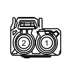 | Yes
GO to A7 . No GO to A5 . | ||||||||||||
| A5 CHECK THE ANTENNA ENABLE CIRCUIT FOR A SHORT TO GROUND | |||||||||||||
 | Yes
GO to A6 . No REPAIR the circuit. | ||||||||||||
| A6 CHECK THE ANTENNA ENABLE CIRCUIT BETWEEN THE ACM AND ANTENNA MODULE FOR AN OPEN | |||||||||||||
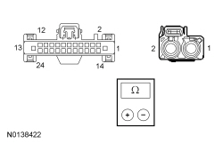 | Yes
GO to A9 . No REPAIR the circuit. | ||||||||||||
| A7 ISOLATE THE ANTENNA MODULE | |||||||||||||
| Yes
The concern was caused by an inoperative antenna module. The system is now operating correctly. No GO to A8 . | ||||||||||||
| A8 CHECK THE AM/FM ANTENNA CABLE | |||||||||||||
| Yes
INSTALL a new AM/FM antenna cable for the inoperative cable. REFER to Antenna Cable — AM/FM . No GO to A9 . | ||||||||||||
| A9 CHECK FOR CORRECT ACM OPERATION | |||||||||||||
| Yes
CHECK OASIS for any applicable TSBs. If a TSB exists for this concern, DISCONTINUE this test and FOLLOW TSB instructions. If no TSBs address this concern, INSTALL a new ACM . REFER to Audio Control Module (ACM) . No The system is operating correctly at this time. The concern may have been caused by module connections. ADDRESS the root cause of any connector or pin issues. | ||||||||||||
Pinpoint Test B: The Satellite Radio Is Inoperative, Has Poor Reception Or No Sound
Diagnostics in this manual assume a certain skill level and knowledge of Ford-specific diagnostic practices. Refer to Diagnostic Methods in Section 100-00 for information about these practices.
Refer to Wiring Diagrams Cell 130 , Audio System/Navigation for schematic and connector information.
Digital signals are received by the satellite radio antenna and sent to the Audio Front Control Module (ACM), as the satellite radio receiver is built into the ACM .
When a satellite radio subscription is activated, the ESN of the built into satellite receiver is associated with the VIN . As a result, the ACM cannot be swapped from one vehicle to another.
Obstructions to the antenna line of sight can affect reception, but this is considered normal operation. Possible obstructions include hills, tall buildings, tunnels, and being parked inside a garage. Be sure the vehicle is in a clear area, free of obstructions, before testing satellite radio reception.
DTC Fault Trigger Conditions
| DTC | Description | Fault Trigger Conditions |
|---|---|---|
| B1A89:11 | Satellite Antenna: Circuit Short To Ground | Set by the ACM when a short to ground is detected in the satellite antenna circuit. This DTC can be either continuous or on-demand. |
| B1A89:13 | Satellite Antenna: Circuit Open | Set by the ACM when an open is detected in the satellite antenna circuit. This DTC can be either continuous or on-demand. |
| U3000:96 | Control Module: Component Internal Failure | Set by the ACM when a fault is detected in the internal satellite radio receiver. This results in complete loss of satellite radio functionality. |
Verify that the satellite radio subscription has not expired.
| Test Step | Result / Action to Take |
|---|---|
| B1 CHECK THE ACM DTCs | |
| Yes
If DTC B1A89:11 or DTC B1A89:13 is present, GO to B3 . If DTC U3000:96 is present, INSTALL a new ACM . REFER to Audio Control Module (ACM) . For all other DTCs, REFER to DTC Charts in this section. No GO to B2 . |
| B2 CHECK THE RECEPTION AND CATEGORY FILTER SETTING | |
| Yes
The system is operating correctly at this time. The concern was a result of no channel being found in the selected category or obstructions to the antenna line of sight. No GO to B3 . |
| B3 CHECK THE SATELLITE SIGNAL PID (SAT_SIG_STR) | |
| Yes
GO to B4 . No GO to B6 . |
| B4 CHECK THE SATELLITE RADIO ANTENNA CABLE RESISTANCE | |
| Yes
GO to B5 . No INSTALL a new front or rear satellite radio antenna cable, as necessary. REFER to Antenna Cable — Satellite Radio . CLEAR any DTCs present. TEST the system for normal operation. |
| B5 ISOLATE THE SATELLITE RADIO ANTENNA | |
| Yes
The concern was caused by an inoperative satellite radio antenna. The system is operating correctly at this time. CLEAR any DTCs present. No GO to B6 . |
| B6 CHECK FOR CORRECT ACM OPERATION | |
| Yes
CHECK OASIS for any applicable TSBs. If a TSB exists for this concern, DISCONTINUE this test and FOLLOW TSB instructions. If no TSBs address this concern, INSTALL a new audio ACM . REFER to Audio Control Module (ACM) . No The system is operating correctly at this time. The concern may have been caused by module connections. ADDRESS the root cause of any connector or pin issues. |
Pinpoint Test C: No Sound From All Speakers
Diagnostics in this manual assume a certain skill level and knowledge of Ford-specific diagnostic practices. Refer to Diagnostic Methods in Section 100-00 for information about these practices.
Refer to Wiring Diagrams Cell 130 , Audio System/Navigation for schematic and connector information.
When the key is in START, the ACM receives voltage on the START signal circuit. The ACM then mutes the speaker output to prevent voltage spikes from producing a popping noise through the speakers. However, a short to voltage on this circuit causes the ACM output to be continuously muted.
If a speaker circuit fault DTC is set in the ACM , the cause of the concern is a short to ground or short to voltage in an individual speaker circuit, which has caused the ACM overload protection to activate. If a speaker circuit fault DTC is present, refer to DTC Charts in this section.
| Test Step | Result / Action to Take | ||||||||||||
|---|---|---|---|---|---|---|---|---|---|---|---|---|---|
| C1 CHECK THE START SIGNAL CIRCUIT FOR A SHORT TO VOLTAGE | |||||||||||||
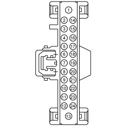 | Yes
REPAIR the circuit. No GO to C2 . | ||||||||||||
| C2 CHECK FOR SPEAKER DTCs | |||||||||||||
| Yes
REFER to ACM DTC Chart in this section. No GO to C3 . | ||||||||||||
| C3 CHECK FOR CORRECT ACM OPERATION | |||||||||||||
| Yes
CHECK OASIS for any applicable TSBs. If a TSB exists for this concern, DISCONTINUE this test and FOLLOW TSB instructions. If no TSBs address this concern, INSTALL a new ACM . REFER to Audio Control Module (ACM) . No The system is operating correctly at this time. The concern may have been caused by module connections. ADDRESS the root cause of any connector or pin issues. | ||||||||||||
Pinpoint Test D: The Steering Wheel Controls Are Inoperative Or Do Not Operate Correctly
Diagnostics in this manual assume a certain skill level and knowledge of Ford-specific diagnostic practices. Refer to Diagnostic Methods in Section 100-00 for information about these practices.
Refer to Wiring Diagrams Cell 130 , Audio System/Navigation for schematic and connector information.
Refer to Steering Wheel Switch Functions in Information and Entertainment System .
DTC Fault Trigger Conditions
| DTC | Description | Fault Trigger Conditions |
|---|---|---|
| B1380:09 | Steering Wheel Right Switch Pack: Component Failure | A continuous and on-demand DTC that sets in the SCCM when the SCCM detects any of the RH steering wheel switch buttons are stuck closed. |
| B1380:11 | Steering Wheel Right Switch Pack: Circuit Short to Ground | A continuous and on-demand DTC that sets in the SCCM when the SCCM detects a short to ground on the RH steering wheel switches input circuit. |
| B1380:17 | Steering Wheel Right Switch Pack: Circuit Voltage Above Threshold | A continuous and on-demand DTC that sets in the SCCM when the SCCM detects an open or short to voltage on the RH steering wheel switches input circuit. |
Inspect the RH steering wheel switches for sticking condition.
| Test Step | Result / Action to Take | ||||||||||||||||||||||||
|---|---|---|---|---|---|---|---|---|---|---|---|---|---|---|---|---|---|---|---|---|---|---|---|---|---|
| D1 RETRIEVE THE RECORDED DTCs FROM THE IPC SELF-TEST | |||||||||||||||||||||||||
| Yes
REFER to Section 413-01 . No GO to D2 . | ||||||||||||||||||||||||
| D2 CHECK THE RH STEERING WHEEL SWITCH PIDS | |||||||||||||||||||||||||
| Yes
GO to D6 . No If only one PID value is incorrect or the PID value always reads one particular switch position, INSTALL a new steering wheel switch. Refer to Section 211-05 . Otherwise, GO to D3 . | ||||||||||||||||||||||||
| D3 CHECK FOR VOLTAGE TO THE RH STEERING WHEEL SWITCHES | |||||||||||||||||||||||||
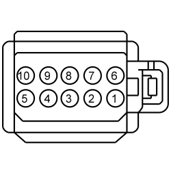 | Yes
INSTALL a new RH steering wheel switch. REFER to Section 211-05 . No GO to D4 . | ||||||||||||||||||||||||
| D4 CHECK FOR VOLTAGE TO THE CLOCKSPRING | |||||||||||||||||||||||||
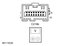 | Yes
INSTALL a new steering wheel. REFER to Section 211-04 . No GO to D5 . | ||||||||||||||||||||||||
| D5 CHECK FOR VOLTAGE AT THE SCCM | |||||||||||||||||||||||||
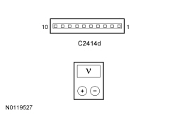 | Yes
INSTALL a new clockspring. REFER to Section 501-20B . No GO to D6 . | ||||||||||||||||||||||||
| D6 CHECK FOR CORRECT SCCM OPERATION | |||||||||||||||||||||||||
| Yes
CHECK OASIS for any applicable TSBs. If a TSB exists for this concern, DISCONTINUE this test and FOLLOW TSB instructions. If no TSBs address this concern, INSTALL a new SCCM . REFER to Section 211-05 . No The system is operating correctly at this time. The concern may have been caused by module connections. ADDRESS the root cause of any connector or pin issues. | ||||||||||||||||||||||||
Pinpoint Test E: The Audio Input Jack Is Inoperative Or Has Poor Sound Quality
Diagnostics in this manual assume a certain skill level and knowledge of Ford-specific diagnostic practices. Refer to Diagnostic Methods in Section 100-00 for information about these practices.
Refer to Wiring Diagrams Cell 130 , Audio System/Navigation for schematic and connector information.
Refer to Audio Input Jack Mode in Information and Entertainment System .
Make sure the MP3 device is operating correctly.
| Test Step | Result / Action to Take | ||||||||||||||||||||
|---|---|---|---|---|---|---|---|---|---|---|---|---|---|---|---|---|---|---|---|---|---|
| E1 CHECK THE AUDIO INPUT JACK AUDIO | |||||||||||||||||||||
| Yes
The system is operating correctly at this time. The concern may be with the customer device. No GO to E2 . | ||||||||||||||||||||
| E2 VERIFY THE OPERATION OF THE SYNC® SYSTEM AUDIO SOURCES | |||||||||||||||||||||
| Yes
GO to E3 . No GO to Pinpoint Test h to diagnose the audio signal from the APIM to the ACM . | ||||||||||||||||||||
| E3 CHECK THE AUDIO INPUT JACK CIRCUITS FOR A SHORT TO VOLTAGE | |||||||||||||||||||||
 | Yes
REPAIR the circuit in question. No GO to E4 . | ||||||||||||||||||||
| E4 CHECK THE AUDIO INPUT JACK CIRCUITS FOR A SHORT TO GROUND | |||||||||||||||||||||
 | Yes
GO to E5 . No REPAIR the circuit in question. | ||||||||||||||||||||
| E5 CHECK THE AUDIO INPUT JACK CIRCUITS FOR A SHORT TO SHIELD | |||||||||||||||||||||
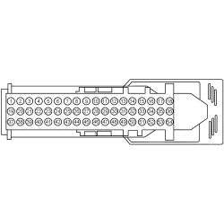 | Yes
GO to E6 . No REPAIR the circuit in question. | ||||||||||||||||||||
| E6 CHECK THE AUDIO INPUT JACK CIRCUITS FOR AN OPEN | |||||||||||||||||||||
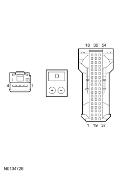 | Yes
GO to E7 . No REPAIR the circuit in question. | ||||||||||||||||||||
| E7 ISOLATE THE AUDIO INPUT JACK | |||||||||||||||||||||
| Yes
The concern was caused by an inoperative audio input jack. The system is now operating correctly. No GO to E8 . | ||||||||||||||||||||
| E8 CHECK FOR CORRECT APIM OPERATION | |||||||||||||||||||||
| Yes
CHECK OASIS for any applicable TSBs. If a TSB exists for this concern, DISCONTINUE this test and FOLLOW TSB instructions. If no TSBs address this concern, For diagnosing and testing please refer to the on-line Workshop Manual. If you do not have an on-line subscription, go to www.motorcraftservice.com. No The system is operating correctly at this time. The concern may have been caused by module connections. ADDRESS the root cause of any connector or pin issues. | ||||||||||||||||||||
Pinpoint Test F: The Speed Compensated Volume Does Not Operate Correctly
Diagnostics in this manual assume a certain skill level and knowledge of Ford-specific diagnostic practices. Refer to Diagnostic Methods in Section 100-00 for information about these practices.
Refer to Speed Compensated Volume in Information and Entertainment System .
Verify the speedometer operates correctly.
| Test Step | Result / Action to Take |
|---|---|
| F1 CHECK THE SPEED SENSITIVE VOLUME SETTING | |
| Yes
The system is operating correctly at this time. INSTRUCT the customer in the correct usage of the speed sensitive volume feature. No GO to F2 . |
| F2 CHECK FOR DTC U0155:00 OR U0184:00 | |
| Yes
For DTC U0155:00, GO to Pinpoint Test Z . For DTC U0184:00, GO to Pinpoint Test AA . No GO to F3 . |
| F3 CHECK FOR CORRECT ACM OPERATION | |
| Yes
CHECK OASIS for any applicable TSBs. If a TSB exists for this concern, DISCONTINUE this test and FOLLOW TSB instructions. If no TSBs address this concern, INSTALL a new ACM . REFER to Audio Control Module (ACM) . No The system is operating correctly at this time. The concern may have been caused by module connections. ADDRESS the root cause of any connector or pin issues. |
Pinpoint Test G: The Audio System Does Not Operate Correctly From The FCIM
Diagnostics in this manual assume a certain skill level and knowledge of Ford-specific diagnostic practices. Refer to Diagnostic Methods in Section 100-00 for information about these practices.
Refer to FCIM in Information and Entertainment System .
DTC Fault Trigger Conditions
| DTC | Description | Fault Trigger Conditions |
|---|---|---|
| U2013:63 | Switch Pack: Circuit/Component Protection Time-Out | Set by the FCIM if a switch is detected as active for more than 3 seconds during the self-test, or for more than 2 minutes during normal operation. When this occurs, the FCIM disables the switch until it detects it as no longer active. |
| Test Step | Result / Action to Take |
|---|---|
| G1 VERIFY THE FCIM PASSES THE NETWORK TEST | |
| Yes
GO to G2 . No REFER to Section 418-00 , The FCIM Does Not Respond To The Scan Tool. |
| G2 CHECK THE FCIM BUTTON PIDs | |
| Yes
GO to G4 . No If only one PID value is incorrect or the PID value always reads one particular switch position, INSTALL a new FCIM . REFER to Front Controls Interface Module (FCIM) . Otherwise, GO to G3 . |
| G3 RESET THE AUDIO SYSTEM MODULES AND RECHECK THE SYSTEM OPERATION | |
| Yes
The concern was resolved by resetting the audio system modules. The FCIM is operating correctly at this time. No GO to G4 . |
| G4 CHECK FOR CORRECT FCIM OPERATION | |
| Yes
CHECK OASIS for any applicable TSBs. If a TSB exists for this concern, DISCONTINUE this test and FOLLOW TSB instructions. If no TSBs address this concern, INSTALL a new FCIM . REFER to Front Controls Interface Module (FCIM) . No The system is operating correctly at this time. The concern may have been caused by module connections. ADDRESS the root cause of any connector or pin issues. |
Pinpoint Test H: Poor Quality, Distorted Or No Sound While In SYNC® Mode
Diagnostics in this manual assume a certain skill level and knowledge of Ford-specific diagnostic practices. Refer to Diagnostic Methods in Section 100-00 for information about these practices.
Refer to Wiring Diagrams Cell 130 , Audio System/Navigation for schematic and connector information.
Refer to SYNC® system in Information and Entertainment System .
The APIM transmits left and right channel analog audio signals to the ACM . These signals include inputs from the USB port, the RCA jack, and a Bluetooth media device. If a USB mass storage device is used to play an audio file, the SYNC® system only plays audio files that do not have DRM protection.
NOTICE: Use the correct probe adapter(s) when making measurements. Failure to use the correct probe adapter(s) may damage the connector.
| Test Step | Result / Action to Take | ||||||||||||||||||||||||
|---|---|---|---|---|---|---|---|---|---|---|---|---|---|---|---|---|---|---|---|---|---|---|---|---|---|
| H1 VERIFY THE OPERATION OF THE SYNC® SYSTEM AUDIO SOURCES | |||||||||||||||||||||||||
| Yes
GO to H2 . No If the concern is only with some (but not all) of the audio sources, GO to Symptom Chart - SYNC System to diagnose the observed symptom. If all audio sources operate correctly, the concern is with the customer device. | ||||||||||||||||||||||||
| H2 CHECK THE CIRCUITS FROM THE APIM FOR A SHORT TO VOLTAGE | |||||||||||||||||||||||||
 | Yes
REPAIR the circuit in question. No GO to H3 . | ||||||||||||||||||||||||
| H3 CHECK THE CIRCUITS FROM THE APIM FOR A SHORT TO GROUND | |||||||||||||||||||||||||
 | Yes
GO to H4 . No REPAIR the circuit in question. | ||||||||||||||||||||||||
| H4 CHECK THE CIRCUITS BETWEEN THE ACM AND THE APIM FOR AN OPEN | |||||||||||||||||||||||||
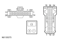 | Yes
GO to H5 . No REPAIR the circuit in question. | ||||||||||||||||||||||||
| H5 CHECK FOR CORRECT APIM OPERATION | |||||||||||||||||||||||||
| Yes
CHECK OASIS for any applicable TSBs. If a TSB exists for this concern, DISCONTINUE this test and FOLLOW TSB instructions. If no TSBs address this concern, For diagnosing and testing please refer to the on-line Workshop Manual. If you do not have an on-line subscription, go to www.motorcraftservice.com. If the concern is still present, GO to H6 . No The system is operating correctly at this time. The concern may have been caused by module connections. ADDRESS the root cause of any connector or pin issues. | ||||||||||||||||||||||||
| H6 CHECK FOR CORRECT ACM OPERATION | |||||||||||||||||||||||||
| Yes
CHECK OASIS for any applicable TSBs. If a TSB exists for this concern, DISCONTINUE this test and FOLLOW TSB instructions. If no TSBs address this concern, INSTALL a new audio ACM . REFER to Audio Control Module (ACM) . No The system is operating correctly at this time. The concern may have been caused by module connections. ADDRESS the root cause of any connector or pin issues. | ||||||||||||||||||||||||
Pinpoint Test J: The FCDIM Is Inoperative Or Does Not Operate Correctly
Diagnostics in this manual assume a certain skill level and knowledge of Ford-specific diagnostic practices. Refer to Diagnostic Methods in Section 100-00 for information about these practices.
Refer to FCDIM in Information and Entertainment System .
| Test Step | Result / Action to Take |
|---|---|
| J1 CHECK FOR SCAN TOOL COMMUNICATION WITH THE FCDIM | |
| Yes
GO to J2 . No Refer to Section 418-00 , The FCDIM Does Not Respond To The Scan Tool. |
| J2 OBSERVE THE FCDIM DISPLAY | |
| Yes
GO to J4 . No GO to J3 . |
| J3 CHECK FOR LOST COMMUNICATION DTCs SET IN THE FCDIM | |
| Yes
REFER to DTC Charts in this section. No GO to J4 . |
| J4 CHECK FOR CORRECT FCDIM OPERATION | |
| Yes
CHECK OASIS for any applicable TSBs. If a TSB exists for this concern, DISCONTINUE this test and FOLLOW TSB instructions. If no TSBs address this concern, INSTALL a new FCDIM . REFER to Front Controls/Display Interface Module (FCDIM) . No The system is operating correctly at this time. The concern may have been caused by module connections. ADDRESS the root cause of any connector or pin issues. |
Pinpoint Test K: The LF A-Pillar Tweeter Speaker Is Inoperative
Diagnostics in this manual assume a certain skill level and knowledge of Ford-specific diagnostic practices. Refer to Diagnostic Methods in Section 100-00 for information about these practices.
Refer to Wiring Diagrams Cell 130 , Audio System/Navigation for schematic and connector information.
The ACM directs audio signals to the LF speakers in the form of a fluctuating AC voltage. The LF tweeter speaker and the LF door speaker share the same audio signal.
DTC Fault Trigger Conditions
| DTC | Description | Fault Trigger Conditions |
|---|---|---|
| B1A01:01 | Speaker #1: General Electrical Failure | Sets when a failure is detected on the LF speaker circuits |
| B1A01:11 | Speaker #1: Circuit Short To Ground | Sets when a short to ground is detected on the LF speaker circuits. When DTC B1A01:11 is set, the speaker output is disabled. |
| B1A01:12 | Speaker #1: Circuit Short To Battery | Sets when a short to battery is detected on the LF speaker circuits. When DTC B1A01:12 is set, the speaker output is disabled. |
| Test Step | Result / Action to Take | ||||||||||||||||
|---|---|---|---|---|---|---|---|---|---|---|---|---|---|---|---|---|---|
| K1 CHECK THE LF DOOR SPEAKER | |||||||||||||||||
| Yes
GO to K2 . No GO to Pinpoint Test M . | ||||||||||||||||
| K2 CHECK THE AUDIO SIGNAL TO THE LF A-PILLAR TWEETER SPEAKER | |||||||||||||||||
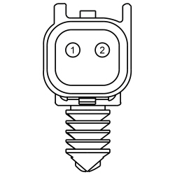 | Yes
INSTALL a new LF A-Pillar tweeter speaker. REFER to Speaker — A-Pillar . No GO to K3 . | ||||||||||||||||
| K3 CHECK THE AUDIO CIRCUITS TO THE LF A-PILLAR TWEETER SPEAKER FOR A SHORT TO VOLTAGE | |||||||||||||||||
 | Yes
REPAIR the circuit in question. No GO to K4 . | ||||||||||||||||
| K4 CHECK THE AUDIO CIRCUITS TO THE LF A-PILLAR TWEETER SPEAKER FOR A SHORT TO GROUND | |||||||||||||||||
 | Yes
GO to K5 . No REPAIR the circuit in question. | ||||||||||||||||
| K5 CHECK THE AUDIO CIRCUITS FOR A SHORT TOGETHER | |||||||||||||||||
 | Yes
GO to K6 . No REPAIR the circuits. | ||||||||||||||||
| K6 CHECK THE AUDIO CIRCUITS BETWEEN THE LF DOOR SPEAKER AND THE LF A-PILLAR TWEETER SPEAKER FOR AN OPEN | |||||||||||||||||
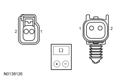 | Yes
INSTALL a new LF door speaker. REFER to Speaker — Door . No REPAIR the circuit in question. | ||||||||||||||||
Pinpoint Test L: The RF A-Pillar Tweeter Speaker Is Inoperative
Diagnostics in this manual assume a certain skill level and knowledge of Ford-specific diagnostic practices. Refer to Diagnostic Methods in Section 100-00 for information about these practices.
Refer to Wiring Diagrams Cell 130 , Audio System/Navigation for schematic and connector information.
The ACM directs audio signals to the RF speakers in the form of a fluctuating AC voltage. The RF tweeter speaker and the RF door speaker share the same audio signal.
DTC Fault Trigger Conditions
| DTC | Description | Fault Trigger Conditions |
|---|---|---|
| B1A02:01 | Speaker #2: General Electrical Failure | Sets when a failure is detected on the RF speaker circuits. |
| B1A02:11 | Speaker #2: Circuit Short To Ground | Sets when a short to ground is detected on the RF speaker circuits. When DTC B1A02:11 is set, the speaker output is disabled. |
| B1A02:12 | Speaker #2: Circuit Short To Battery | Sets when a short to battery is detected on the RF speaker circuits. When DTC B1A02:12 is set, the speaker output is disabled. |
| Test Step | Result / Action to Take | ||||||||||||||||
|---|---|---|---|---|---|---|---|---|---|---|---|---|---|---|---|---|---|
| L1 CHECK THE RF DOOR SPEAKER | |||||||||||||||||
| Yes
GO to L2 . No GO to Pinpoint Test N . | ||||||||||||||||
| L2 CHECK THE AUDIO SIGNAL TO THE RF A-PILLAR TWEETER SPEAKER | |||||||||||||||||
 | Yes
INSTALL a new RF A-Pillar Tweeter speaker. REFER to Speaker — A-Pillar . No GO to L3 . | ||||||||||||||||
| L3 CHECK THE AUDIO CIRCUITS TO THE RF A-PILLAR TWEETER SPEAKER FOR A SHORT TO VOLTAGE | |||||||||||||||||
 | Yes
REPAIR the circuit in question. No GO to L4 . | ||||||||||||||||
| L4 CHECK THE AUDIO CIRCUITS TO THE RF A-PILLAR TWEETER SPEAKER FOR A SHORT TO GROUND | |||||||||||||||||
 | Yes
GO to L5 . No REPAIR the circuit in question. | ||||||||||||||||
| L5 CHECK THE AUDIO CIRCUITS FOR A SHORT TOGETHER | |||||||||||||||||
 | Yes
GO to L6 . No REPAIR the circuits. | ||||||||||||||||
| L6 CHECK THE AUDIO CIRCUITS BETWEEN THE RF DOOR SPEAKER AND THE RF A-PILLAR TWEETER SPEAKER FOR AN OPEN | |||||||||||||||||
 | Yes
INSTALL a new RF door speaker. REFER to Speaker — Door . No REPAIR the circuit in question. | ||||||||||||||||
Pinpoint Test M: The LF Door Speaker Is Inoperative
Diagnostics in this manual assume a certain skill level and knowledge of Ford-specific diagnostic practices. Refer to Diagnostic Methods in Section 100-00 for information about these practices.
Refer to Wiring Diagrams Cell 130 , Audio System/Navigation for schematic and connector information.
DTC Fault Trigger Conditions
| DTC | Description | Fault Trigger Conditions |
|---|---|---|
| B1A01:01 | Speaker #1: General Electrical Failure | Sets when a failure is detected on the LF speaker circuits. |
| B1A01:11 | Speaker #1: Circuit Short To Ground | Sets when a short to ground is detected on the LF speaker circuits. When DTC B1A01:11 is set, the speaker output is disabled. |
| B1A01:12 | Speaker #1: Circuit Short To Battery | Sets when a short to battery is detected on the LF speaker circuits. When DTC B1A01:12 is set, the speaker output is disabled. |
| B1A01:13 | Speaker #1: Circuit Open | Sets when an open is detected on the LF speaker circuits. |
| Test Step | Result / Action to Take | ||||||||||||||||
|---|---|---|---|---|---|---|---|---|---|---|---|---|---|---|---|---|---|
| M1 CHECK THE AUDIO SIGNAL TO THE LF DOOR SPEAKER | |||||||||||||||||
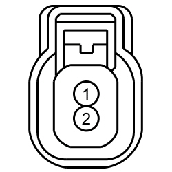 | Yes
INSTALL a new LF door speaker. REFER to Speaker — Door . No GO to M2 . | ||||||||||||||||
| M2 CHECK THE AUDIO CIRCUITS TO THE LF DOOR SPEAKER FOR A SHORT TO VOLTAGE | |||||||||||||||||
 | Yes
REPAIR the circuit in question. No GO to M3 . | ||||||||||||||||
| M3 CHECK THE AUDIO CIRCUITS TO THE LF DOOR SPEAKER FOR A SHORT TO GROUND | |||||||||||||||||
 | Yes
GO to M4 . No REPAIR the circuit in question. | ||||||||||||||||
| M4 CHECK THE AUDIO CIRCUITS FOR A SHORT TOGETHER | |||||||||||||||||
 | Yes
GO to M5 . No REPAIR the circuits. | ||||||||||||||||
| M5 CHECK THE AUDIO CIRCUITS BETWEEN THE ACM AND THE LF DOOR SPEAKER FOR AN OPEN | |||||||||||||||||
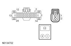 | Yes
GO to M6 . No REPAIR the circuit in question. | ||||||||||||||||
| M6 CHECK FOR CORRECT ACM OPERATION | |||||||||||||||||
| Yes
CHECK OASIS for any applicable TSBs. If a TSB exists for this concern, DISCONTINUE this test and FOLLOW TSB instructions. If no TSBs address this concern, INSTALL a new ACM . REFER to Audio Control Module (ACM) . No The system is operating correctly at this time. The concern may have been caused by module connections. ADDRESS the root cause of any connector or pin issues. | ||||||||||||||||
Pinpoint Test N: The RF Door Speaker Is Inoperative
Diagnostics in this manual assume a certain skill level and knowledge of Ford-specific diagnostic practices. Refer to Diagnostic Methods in Section 100-00 for information about these practices.
Refer to Wiring Diagrams Cell 130 , Audio System/Navigation for schematic and connector information.
DTC Fault Trigger Conditions
| DTC | Description | Fault Trigger Conditions |
|---|---|---|
| B1A02:01 | Speaker #2: General Electrical Failure | Sets when a failure is detected on the RF speaker circuits. |
| B1A02:11 | Speaker #2: Circuit Short To Ground | Sets when a short to ground is detected on the RF speaker circuits. When DTC B1A02:11 is set, the speaker output is disabled. |
| B1A02:12 | Speaker #2: Circuit Short To Battery | Sets when a short to battery is detected on the RF speaker circuits. When DTC B1A02:12 is set, the speaker output is disabled. |
| B1A02:13 | Speaker #2: Circuit Open | Sets when an open is detected on the RF speaker circuits. |
| Test Step | Result / Action to Take | ||||||||||||||||
|---|---|---|---|---|---|---|---|---|---|---|---|---|---|---|---|---|---|
| N1 CHECK THE AUDIO SIGNAL TO THE RF DOOR SPEAKER | |||||||||||||||||
 | Yes
INSTALL a new RF door speaker. REFER to Speaker — Door . No GO to N2 . | ||||||||||||||||
| N2 CHECK THE AUDIO CIRCUITS TO THE RF DOOR SPEAKER FOR A SHORT TO VOLTAGE | |||||||||||||||||
 | Yes
REPAIR the circuit in question. No GO to N3 . | ||||||||||||||||
| N3 CHECK THE AUDIO CIRCUITS TO THE RF DOOR SPEAKER FOR A SHORT TO GROUND | |||||||||||||||||
 | Yes
GO to N4 . No REPAIR the circuit in question. | ||||||||||||||||
| N4 CHECK THE AUDIO CIRCUITS FOR A SHORT TOGETHER | |||||||||||||||||
 | Yes
GO to N5 . No REPAIR the circuits. | ||||||||||||||||
| N5 CHECK THE AUDIO CIRCUITS BETWEEN THE ACM AND THE RF DOOR SPEAKER FOR AN OPEN | |||||||||||||||||
 | Yes
GO to N6 . No REPAIR the circuit in question. | ||||||||||||||||
| N6 CHECK FOR CORRECT ACM OPERATION | |||||||||||||||||
| Yes
CHECK OASIS for any applicable TSBs. If a TSB exists for this concern, DISCONTINUE this test and FOLLOW TSB instructions. If no TSBs address this concern, INSTALL a new ACM . REFER to Audio Control Module (ACM) . No The system is operating correctly at this time. The concern may have been caused by module connections. ADDRESS the root cause of any connector or pin issues. | ||||||||||||||||
Pinpoint Test O: The LR Door Speaker Is Inoperative
Diagnostics in this manual assume a certain skill level and knowledge of Ford-specific diagnostic practices. Refer to Diagnostic Methods in Section 100-00 for information about these practices.
Refer to Wiring Diagrams Cell 130 , Audio System/Navigation for schematic and connector information.
DTC Fault Trigger Conditions
| DTC | Description | Fault Trigger Conditions |
|---|---|---|
| B1A04:01 | Speaker #4: General Electrical Failure | Sets when a failure is detected on the LR door speaker circuits. |
| B1A04:11 | Speaker #4: Circuit Short To Ground | Sets when a short to ground is detected on the LR door speaker circuits. When DTC B1A04:11 is set, the speaker output is disabled. |
| B1A04:12 | Speaker #4: Circuit Short To Battery | Sets when a short to battery is detected on the LR door speaker circuits. When DTC B1A04:12 is set, the speaker output is disabled. |
| B1A04:13 | Speaker #4: Circuit Open | Sets when an open is detected on the LR door speaker circuits. |
| Test Step | Result / Action to Take | ||||||||||||||||
|---|---|---|---|---|---|---|---|---|---|---|---|---|---|---|---|---|---|
| O1 CHECK THE AUDIO SIGNAL TO THE LR DOOR SPEAKER | |||||||||||||||||
 | Yes
INSTALL a new LR door speaker. REFER to Speaker — Door . No GO to O2 . | ||||||||||||||||
| O2 CHECK THE AUDIO CIRCUITS TO THE LR DOOR SPEAKER FOR A SHORT TO VOLTAGE | |||||||||||||||||
 | Yes
REPAIR the circuit in question. No GO to O3 . | ||||||||||||||||
| O3 CHECK THE AUDIO CIRCUITS TO THE LR DOOR SPEAKER FOR A SHORT TO GROUND | |||||||||||||||||
 | Yes
GO to O4 . No REPAIR the circuit in question. | ||||||||||||||||
| O4 CHECK THE AUDIO CIRCUITS FOR A SHORT TOGETHER | |||||||||||||||||
 | Yes
GO to O5 . No REPAIR the circuits. | ||||||||||||||||
| O5 CHECK THE AUDIO CIRCUITS BETWEEN THE ACM AND THE LR DOOR SPEAKER FOR AN OPEN | |||||||||||||||||
 | Yes
GO to O6 . No REPAIR the circuit in question. | ||||||||||||||||
| O6 CHECK FOR CORRECT ACM OPERATION | |||||||||||||||||
| Yes
CHECK OASIS for any applicable TSBs. If a TSB exists for this concern, DISCONTINUE this test and FOLLOW TSB instructions. If no TSBs address this concern, INSTALL a new ACM . REFER to Audio Control Module (ACM) . No The system is operating correctly at this time. The concern may have been caused by module connections. ADDRESS the root cause of any connector or pin issues. | ||||||||||||||||
Pinpoint Test P: The RR Door Speaker Is Inoperative
Diagnostics in this manual assume a certain skill level and knowledge of Ford-specific diagnostic practices. Refer to Diagnostic Methods in Section 100-00 for information about these practices.
Refer to Wiring Diagrams Cell 130 , Audio System/Navigation for schematic and connector information.
DTC Fault Trigger Conditions
| DTC | Description | Fault Trigger Conditions |
|---|---|---|
| B1A03:01 | Speaker #3: General Electrical Failure | Sets when a failure is detected on the RR door speaker circuits. |
| B1A03:11 | Speaker #3: Circuit Short To Ground | Sets when a short to ground is detected on the RR door speaker circuits. When DTC B1A03:11 is set, the speaker output is disabled. |
| B1A03:12 | Speaker #3: Circuit Short To Battery | Sets when a short to battery is detected on the RR door speaker circuits. When DTC B1A03:12 is set, the speaker output is disabled. |
| B1A03:13 | Speaker #3: Circuit Open | Sets when an open is detected on the RR door speaker circuits. |
| Test Step | Result / Action to Take | ||||||||||||||||
|---|---|---|---|---|---|---|---|---|---|---|---|---|---|---|---|---|---|
| P1 CHECK THE AUDIO SIGNAL TO THE RR DOOR SPEAKER | |||||||||||||||||
 | Yes
INSTALL a new RR door speaker. REFER to Speaker — Door . No GO to P2 . | ||||||||||||||||
| P2 CHECK THE AUDIO CIRCUITS TO THE RR DOOR SPEAKER FOR A SHORT TO VOLTAGE | |||||||||||||||||
 | Yes
REPAIR the circuit in question. No GO to P3 . | ||||||||||||||||
| P3 CHECK THE AUDIO CIRCUITS TO THE RR DOOR SPEAKER FOR A SHORT TO GROUND | |||||||||||||||||
 | Yes
GO to P4 . No REPAIR the circuit in question. | ||||||||||||||||
| P4 CHECK THE AUDIO CIRCUITS FOR A SHORT TOGETHER | |||||||||||||||||
 | Yes
GO to P5 . No REPAIR the circuits. | ||||||||||||||||
| P5 CHECK THE AUDIO CIRCUITS BETWEEN THE ACM AND THE RR DOOR SPEAKER FOR AN OPEN | |||||||||||||||||
 | Yes
GO to P6 . No REPAIR the circuit in question. | ||||||||||||||||
| P6 CHECK FOR CORRECT ACM OPERATION | |||||||||||||||||
| Yes
CHECK OASIS for any applicable TSBs. If a TSB exists for this concern, DISCONTINUE this test and FOLLOW TSB instructions. If no TSBs address this concern, INSTALL a new ACM . REFER to Audio Control Module (ACM) . No The system is operating correctly at this time. The concern may have been caused by module connections. ADDRESS the root cause of any connector or pin issues. | ||||||||||||||||
Pinpoint Test S: The SYNC System Is Inoperative (No Response Is Received From Phone, Voice, And Media Inputs)
Diagnostics in this manual assume a certain skill level and knowledge of Ford-specific diagnostic practices. Refer to Diagnostic Methods in Section 100-00 for information about these practices.
Refer to Wiring Diagrams Cell 130 , Audio System/Navigation for schematic and connector information.
Refer to SYNC® system in Information and Entertainment System .
DTC Fault Trigger Conditions
| DTC | Description | Fault Trigger Conditions |
|---|---|---|
| U3000:04 | Control Module: System Internal Failure | Sets when the APIM detects a fault due to a device conflict or an internal failure. |
| Test Step | Result / Action to Take |
|---|---|
| S1 CHECK FOR SCAN TOOL COMMUNICATION WITH THE APIM | |
| Yes
GO to S2 . No REFER to Section 418-00 , The APIM Does Not Respond To The Scan Tool. |
| S2 CHECK THE SYNC® SYSTEM OPERATION | |
NOTE: Carrying out a Master Reset returns all preference settings to the factory defaults, erases all the phone book and call histories, and deletes any devices paired with the SYNC® system. | Yes
The SYNC® system is operating correctly at this time. CARRY OUT a SYNC® system Master Reset. REFER to the Owner's Literature. REVIEW the SYNC® system operation with the customer. If the customer device still does not operate correctly, the fault is with the customer device. No GO to S3 . |
| S3 RESET THE APIM AND RECHECK SYNC® SYSTEM OPERATION | |
| Yes
The SYNC® system is operating correctly at this time. CARRY OUT a SYNC® system Master Reset. REFER to the Owner's Literature. REVIEW the SYNC® system operation with the customer. If the customer device still does not operate correctly, the fault is with the customer device. No If only some (but not all) of the inputs are inoperative, GO to Symptom Chart - SYNC System to diagnose the observed symptom. If all inputs are inoperative and/or DTC U3000:04 is present, For diagnosing and testing please refer to the on-line Workshop Manual. If you do not have an on-line subscription, go to www.motorcraftservice.com. |
Pinpoint Test T: Voice Recognition Is Inoperative Or Does Not Operate Correctly, Or During A Phone Call, Poor Quality Or No Outgoing Audio Is Heard On The Outside Device
Diagnostics in this manual assume a certain skill level and knowledge of Ford-specific diagnostic practices. Refer to Diagnostic Methods in Section 100-00 for information about these practices.
Refer to Wiring Diagrams Cell 130 , Audio System/Navigation for schematic and connector information.
Refer to Voice Recognition in Information and Entertainment System .
DTC Fault Trigger Conditions
| DTC | Description | Fault Trigger Conditions |
|---|---|---|
| B1D79:01 | Microphone Input: General Electrical Failure | Set by the APIM during the on-demand self-test if it does not detect the microphone. |
| B1D79:11 | Microphone Input: Circuit Short to Ground | Sets when the APIM detects a short to ground on the microphone circuits. |
| B1D79:12 | Microphone Input: Circuit Short To Battery | Sets when the APIM detects a short to battery voltage on the microphone circuits. |
| B1D79:13 | Microphone Input: Circuit Open | Sets when the APIM detects an open on the microphone circuits. |
| Test Step | Result / Action to Take | ||||||||||||||||
|---|---|---|---|---|---|---|---|---|---|---|---|---|---|---|---|---|---|
| T1 CHECK THE AUDIBLE PROMPT FUNCTIONALITY | |||||||||||||||||
| Yes
GO to T3 . No GO to T2 . | ||||||||||||||||
| T2 CHECK THE OPERATION OF THE RH LOWER STEERING WHEEL SWITCHES | |||||||||||||||||
| Yes
GO to Pinpoint Test W . No GO to Pinpoint Test D to diagnose the RH lower steering wheel switches. | ||||||||||||||||
| T3 CHECK THE OPERATION OF THE "PHONE" VOICE COMMAND | |||||||||||||||||
| Yes
For a concern with the voice recognition being inoperative or not operating correctly, the system is operating correctly at this time. The concern may have been caused by an insufficiently quiet vehicle. Delete the just-paired Bluetooth phone from the SYNC® system. For information on deleting a Bluetooth device from the SYNC® system, refer to the Owner's Literature. For a concern with poor quality or no outgoing audio being heard on the outside device during a phone call, GO to T4 No GO to T5 . | ||||||||||||||||
| T4 CHECK THE OUTGOING PHONE CALL QUALITY AND VOICE VOLUME | |||||||||||||||||
| Yes
The system is operating correctly at this time. The concern may have been caused by poor phone reception or an insufficiently quiet vehicle. No GO to T5 . | ||||||||||||||||
| T5 CHECK THE MICROPHONE AND MICROPHONE CIRCUITS FOR CORRECT VOLTAGE DROP | |||||||||||||||||
NOTICE: This pinpoint test step directs testing circuits using a back-probe method. Use the special back-probe tool POM6411. Do not force test leads or other probes into connectors. Adequate care must be exercised to avoid connector terminal damage, while ensuring that good electrical contact is made with the circuit or terminal. Failure to follow these instructions may cause damage to wiring, terminals, or connectors, and may cause subsequent electrical faults.
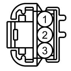 | Yes
If diagnosing an intermittent concern, GO to T6 . If not diagnosing an intermittent concern, GO to T12 No GO to T7 . | ||||||||||||||||
| T6 CHECK THE MICROPHONE CIRCUITS FOR INTERMITTENT CONCERNS | |||||||||||||||||
NOTICE: This pinpoint test step directs testing circuits using a back-probe method. Use the special back-probe tool POM6411. Do not force test leads or other probes into connectors. Adequate care must be exercised to avoid connector terminal damage, while ensuring that good electrical contact is made with the circuit or terminal. Failure to follow these instructions may cause damage to wiring, terminals, or connectors, and may cause subsequent electrical faults.
 | Yes
REPAIR the circuit(s), connector, or terminal(s) in question. For corrosion, clean pins or install a new connector or terminals. For damaged or bent pins, install new terminals or pins. No GO to T11 . | ||||||||||||||||
| T7 CHECK THE MICROPHONE CIRCUITS TO THE APIM FOR A SHORT TO VOLTAGE | |||||||||||||||||
 | Yes
REPAIR the circuit in question. No GO to T8 . | ||||||||||||||||
| T8 CHECK THE MICROPHONE CIRCUITS TO THE APIM FOR A SHORT TO GROUND | |||||||||||||||||
 | Yes
GO to T9 . No REPAIR the circuit in question. | ||||||||||||||||
| T9 CHECK THE MICROPHONE CIRCUITS BETWEEN THE MICROPHONE AND THE APIM FOR AN OPEN | |||||||||||||||||
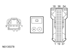 | Yes
GO to T10 . No REPAIR the circuit in question. | ||||||||||||||||
| T10 CHECK THE MICROPHONE CIRCUITS TO THE APIM FOR A SHORT TOGETHER | |||||||||||||||||
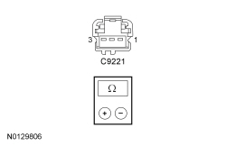 | Yes
GO to T12 . No REPAIR the circuit in question. | ||||||||||||||||
| T11 ISOLATE THE MICROPHONE | |||||||||||||||||
| Yes
The concern was caused by an inoperative microphone. The system is operating correctly at this time. No GO to T12 . | ||||||||||||||||
| T12 CHECK FOR CORRECT APIM OPERATION | |||||||||||||||||
| Yes
CHECK OASIS for any applicable TSBs. If a TSB exists for this concern, DISCONTINUE this test and FOLLOW TSB instructions. If no TSBs address this concern, For diagnosing and testing please refer to the on-line Workshop Manual. If you do not have an on-line subscription, go to www.motorcraftservice.com. No The system is operating correctly at this time. The concern may have been caused by module connections. ADDRESS the root cause of any connector or pin issues. | ||||||||||||||||
Pinpoint Test U: Unable To Pair Bluetooth Device
Diagnostics in this manual assume a certain skill level and knowledge of Ford-specific diagnostic practices. Refer to Diagnostic Methods in Section 100-00 for information about these practices.
Refer to Wiring Diagrams Cell 130 , Audio System/Navigation for schematic and connector information.
Refer to Bluetooth Mode in Information and Entertainment System .
| Test Step | Result / Action to Take |
|---|---|
| U1 CHECK THE BLUETOOTH CONNECTION | |
NOTE: Carrying out a Master Reset returns all preference settings to the factory defaults, erases all the phone book and call histories, and deletes any devices paired with the SYNC® system. | Yes
The SYNC® system is operating correctly at this time. CARRY OUT a SYNC® system Master Reset. REFER to the Owner's Literature. REVIEW the pairing process with the customer. If the customer device still does not pair, the fault is with the customer device. No GO to U2 . |
| U2 CHECK FOR CORRECT APIM OPERATION | |
| Yes
CHECK OASIS for any applicable TSBs. If a TSB exists for this concern, DISCONTINUE this test and FOLLOW TSB instructions. If no TSBs address this concern, For diagnosing and testing please refer to the on-line Workshop Manual. If you do not have an on-line subscription, go to www.motorcraftservice.com. No The system is operating correctly at this time. The concern may have been caused by module connections. ADDRESS the root cause of any connector or pin issues. |
Pinpoint Test V: The USB Port Is Inoperative Or Does Not Operate Correctly
Diagnostics in this manual assume a certain skill level and knowledge of Ford-specific diagnostic practices. Refer to Diagnostic Methods in Section 100-00 for information about these practices.
Refer to Wiring Diagrams Cell 130 , Audio System/Navigation for schematic and connector information.
Refer to USB Audio Mode in Information and Entertainment System .
DTC Fault Trigger Conditions
| DTC | Description | Fault Trigger Conditions |
|---|---|---|
| B1252:04 | USB Port: System Internal Failure | Set when the APIM detects an over-temperature condition in the USB circuit. This can be caused by a fault in the USB cable and port, or by the customer USB device. |
| B1252:11 | USB Port: Circuit Short to Ground | Sets when the APIM detects an over-current condition in the USB circuit. This can be caused by a fault in the USB cable and port, or by the customer USB device. |
| Test Step | Result / Action to Take |
|---|---|
| V1 CHECK THE USB CONNECTION | |
| Yes
The SYNC® system is operating correctly. REVIEW the operation of the USB port with the customer. If the customer device still does not operate correctly, the fault is with the customer device. No GO to V2 . |
| V2 INSPECT THE USB CABLE | |
| Yes
The concern was caused by the USB connection not being seated correctly. The system is now operating correctly. No GO to V3 . |
| V3 RESET THE APIM AND RECHECK SYNC® SYSTEM OPERATION | |
NOTE: Carrying out a Master Reset returns all preference settings to the factory defaults, erases all the phone book and call histories, and deletes any devices paired with the SYNC® system. | Yes
The SYNC® system is operating correctly at this time. CARRY OUT a SYNC® system Master Reset. REFER to the Owner's Literature. REVIEW the SYNC® system operation with the customer. If the customer device still does not operate correctly, the fault is with the customer device. No GO to V4 . |
| V4 ISOLATE THE USB CABLE AND PORT | |
| Yes
The concern was caused by an inoperative USB cable. The system is now operating correctly. No GO to V5 . |
| V5 CHECK FOR CORRECT APIM OPERATION | |
| Yes
CHECK OASIS for any applicable TSBs. If a TSB exists for this concern, DISCONTINUE this test and FOLLOW TSB instructions. If no TSBs address this concern, For diagnosing and testing please refer to the on-line Workshop Manual. If you do not have an on-line subscription, go to www.motorcraftservice.com. No The system is operating correctly at this time. The concern may have been caused by module connections. ADDRESS the root cause of any connector or pin issues. |
Pinpoint Test W: The SYNC® System Voice Or Tone Prompts, Text-To-Speech (TTS) Feature, Or Ringtones Are Inoperative Or Do Not Operate Correctly
Diagnostics in this manual assume a certain skill level and knowledge of Ford-specific diagnostic practices. Refer to Diagnostic Methods in Section 100-00 for information about these practices.
Refer to Wiring Diagrams Cell 130 , Audio System/Navigation for schematic and connector information.
Refer to SYNC® system and Audible Prompts in Information and Entertainment System .
| Test Step | Result / Action to Take | ||||||||||||||||
|---|---|---|---|---|---|---|---|---|---|---|---|---|---|---|---|---|---|
| W1 CHECK THE AUDIBLE PROMPT SETTING | |||||||||||||||||
| Yes
The system is operating correctly at this time. The concern was caused by a customer setting. INSTRUCT the customer in the correct operation of the audible prompt feature. No GO to W2 . | ||||||||||||||||
| W2 CHECK FOR A VOLTAGE SIGNAL FROM THE APIM | |||||||||||||||||
NOTICE: This pinpoint test step directs testing circuits using a back-probe method. Use the special back-probe tool specified in the tool list in this section. Do not force test leads or other probes into connectors. Adequate care must be exercised to avoid connector terminal damage while ensuring that good electrical contact is made with the circuit or terminal. Failure to follow these instructions may cause damage to wiring, terminals, or connectors and subsequent electrical faults.
| Yes
GO to W7 . No GO to W3 . | ||||||||||||||||
| W3 CHECK THE AUDIBLE PROMPT CIRCUITS FOR A SHORT TO VOLTAGE | |||||||||||||||||
 | Yes
REPAIR the circuit in question. No GO to W4 . | ||||||||||||||||
| W4 CHECK THE AUDIBLE PROMPT CIRCUITS FOR A SHORT TO GROUND | |||||||||||||||||
 | Yes
GO to W5 . No REPAIR the circuit in question. | ||||||||||||||||
| W5 CHECK THE AUDIBLE PROMPT CIRCUITS BETWEEN THE ACM AND THE APIM FOR AN OPEN | |||||||||||||||||
 | Yes
GO to W6 . No REPAIR the circuit in question. | ||||||||||||||||
| W6 CHECK FOR CORRECT APIM OPERATION | |||||||||||||||||
| Yes
CHECK OASIS for any applicable TSBs. If a TSB exists for this concern, DISCONTINUE this test and FOLLOW TSB instructions. If no TSBs address this concern, For diagnosing and testing please refer to the on-line Workshop Manual. If you do not have an on-line subscription, go to www.motorcraftservice.com. No The system is operating correctly at this time. The concern may have been caused by module connections. ADDRESS the root cause of any connector or pin issues. | ||||||||||||||||
| W7 CHECK FOR CORRECT ACM OPERATION | |||||||||||||||||
| Yes
CHECK OASIS for any applicable TSBs. If a TSB exists for this concern, DISCONTINUE this test and FOLLOW TSB instructions. If no TSBs address this concern, INSTALL a new audio ACM . REFER to Audio Control Module (ACM) . No The system is operating correctly at this time. The concern may have been caused by module connections. ADDRESS the root cause of any connector or pin issues. | ||||||||||||||||
Pinpoint Test X: All Sync® Services Features Are Inoperative Or Inaccurate (Traffic, Directions, And Information)
Diagnostics in this manual assume a certain skill level and knowledge of Ford-specific diagnostic practices. Refer to Diagnostic Methods in Section 100-00 for information about these practices.
Refer to the SYNC® Traffic, Directions and Information in Information and Entertainment System .
| Test Step | Result / Action to Take |
|---|---|
| X1 CHECK FOR APIM DTCs | |
| Yes
REFER to Accessory Protocol Interface Module (APIM) DTC Chart in this section. No GO to X2 . |
| X2 CHECK FOR GPSM DTCs | |
| Yes
REFER to Global Positioning System Module (GPSM) DTC Chart in this section. No GO to X3 . |
| X3 VERIFY THE CUSTOMER SUBSCRIPTION AND PHONE NUMBER | |
| Yes
GO to X4 . No If the subscription is not activated, INFORM the customer that in order for the SYNC® traffic, directions and information to function, the subscription needs to be activated on the SYNC® website. REFER to the SyncMyRide website . If the phone number is incorrect, INFORM the customer that the correct phone number must be registered on the SYNC® website. REFER to the SyncMyRide website . |
| X4 VERIFY THE CUSTOMER'S PHONE CONNECTION TO SYNC® TRAFFIC, DIRECTIONS AND INFORMATION SERVICES | |
| Yes
GO to X5 . No REFER to GO to Pinpoint Test u |
| X5 OBSERVE THE SYNC® TRAFFIC, DIRECTIONS AND INFORMATION SERVICES SUBSCRIPTION COMMERCIAL | |
| Yes
There is a potential SYNC® traffic, directions and information services issue and the problem does not reside in the vehicles audio system. CONTACT the Ford Technical Hotline for assistance. No GO to X6 . |
| X6 CHECK THE OPERATION OF THE DIRECTIONS FROM THE SYNC® TRAFFIC, DIRECTIONS AND INFORMATION SERVICES | |
| Yes
The SYNC® traffic, directions and information services is operating correctly at this time. No If no chime is heard and an audible prompt indicating that the system was unable to locate the vehicle, there is a potential SYNC® traffic, directions and information services issue and the problem does not reside in the vehicles audio system. CONTACT the Ford Technical Hotline for assistance. If a single chime heard and an audible prompt indicating the navigation route is being sent to the vehicle followed by a repeating chime, GO to X7 . |
| X7 REPROGRAM THE APIM | |
| Yes
The concern was resolved by reflashing the APIM . The SYNC® traffic, directions and information services is operating correctly at this time. No GO to X8 . |
| X8 CHECK FOR CORRECT APIM OPERATION | |
| Yes
CHECK OASIS for any applicable TSBs. If a TSB exists for this concern, DISCONTINUE this test and FOLLOW TSB instructions. If no TSBs address this concern, For diagnosing and testing please refer to the on-line Workshop Manual. If you do not have an on-line subscription, go to www.motorcraftservice.com. If the concern is still present, INSTALL a new a new GPSM . REFER to Global Positioning System Module (GPSM) . No The system is operating correctly at this time. The concern may have been caused by module connections. ADDRESS the root cause of any connector or pin issues. |
Pinpoint Test Y: DTC U0140:00
Diagnostics in this manual assume a certain skill level and knowledge of Ford-specific diagnostic practices. Refer to Diagnostic Methods in Section 100-00 for information about these practices.
DTC Fault Trigger Conditions
| DTC | Description | Fault Trigger Conditions |
|---|---|---|
| U0140:00 | Lost Communication With Body Control Module: No Sub Type Information | Set by the APIM or the GPSM , when network messages are missing from the BCM for greater than 5 seconds with the ignition in RUN. |
| Test Step | Result / Action to Take |
|---|---|
| Y1 VERIFY THE CUSTOMER CONCERN | |
| Yes
GO to Y2 . No The system is operating correctly at this time. The DTC may have been set due to high network traffic or an intermittent fault condition. |
| Y2 CHECK FOR LOST COMMUNICATION DTCs | |
| Yes
GO to Y3 . No The system is operating normally at this time. The DTC may have been set due to high network traffic or an intermittent fault condition. |
| Y3 CHECK FOR BATTERY VOLTAGE OUT-OF-RANGE DTCs | |
| Yes
For an audio system module, REFER to DTC Charts in this section. For the BCM , REFER to Section 419-10 . No GO to Y4 . |
| Y4 CHECK FOR DTC U0140:00 SET IN MULTIPLE MODULES | |
| Yes
GO to Y5 . No If there is an observable symptom, GO to Symptom Chart - General Audio System . If there is no observable symptom, CHECK the I-CAN or MS-CAN wiring between the BCM and the module in question for an intermittent fault. |
| Y5 CHECK FOR CORRECT BCM OPERATION | |
| Yes
CHECK OASIS for any applicable TSBs. If a TSB exists for this concern, DISCONTINUE this test and FOLLOW TSB instructions. If no TSBs address this concern, INSTALL a new BCM . REFER to Section 419-10 . No The system is operating correctly at this time. The concern may have been caused by module connections. ADDRESS the root cause of any connector or pin issues. |
Pinpoint Test Z: DTC U0155:00
Diagnostics in this manual assume a certain skill level and knowledge of Ford-specific diagnostic practices. Refer to Diagnostic Methods in Section 100-00 for information about these practices.
DTC Fault Trigger Conditions
| DTC | Description | Fault Trigger Conditions |
|---|---|---|
| U0155:00 | Lost Communication With Instrument Panel Cluster ( IPC ) | Set by the ACM , the FCIM , the FCDIM , the GPSM or the APIM when network messages are missing from the IPC for greater than 5 seconds with the ignition in RUN. |
| Test Step | Result / Action to Take |
|---|---|
| Z1 VERIFY THE CUSTOMER CONCERN | |
| Yes
GO to Z2 . No The system is operating correctly at this time. The DTC may have been set due to high network traffic or an intermittent fault condition. |
| Z2 CHECK FOR LOST COMMUNICATION DTCs | |
| Yes
GO to Z3 . No The system is operating correctly at this time. The DTC may have been set due to high network traffic or an intermittent fault condition. |
| Z3 CHECK FOR BATTERY VOLTAGE OUT-OF-RANGE DTCs | |
| Yes
For an audio system module, REFER to DTC Charts in this section. For IPC , REFER to Section 413-01 . No GO to Z4 . |
| Z4 CHECK FOR DTC U0155:00 SET IN MULTIPLE MODULES | |
| Yes
GO to Z5 . No If there is an observable symptom, GO to Symptom Chart - General Audio System . If there is no observable symptom, CHECK the I-CAN wiring between the IPC and the module in question for an intermittent fault. |
| Z5 CHECK FOR CORRECT IPC OPERATION | |
| Yes
CHECK OASIS for any applicable TSBs. If a TSB exists for this concern, DISCONTINUE this test and FOLLOW TSB instructions. If no TSBs address this concern, INSTALL a new IPC . REFER to Section 413-01 . No The system is operating correctly at this time. The concern may have been caused by module connections. ADDRESS the root cause of any connector or pin issues. |
Pinpoint Test AA: DTC U0184:00
Diagnostics in this manual assume a certain skill level and knowledge of Ford-specific diagnostic practices. Refer to Diagnostic Methods in Section 100-00 for information about these practices.
DTC Fault Trigger Conditions
| DTC | Description | Fault Trigger Conditions |
|---|---|---|
| U0184:00 | Lost Communication With Radio: No Sub Type Information | Set by the FCDIM when network messages are missing from the ACM over the I-CAN for greater than 5 seconds with the ignition in the RUN position. |
| Test Step | Result / Action to Take |
|---|---|
| AA1 VERIFY THE CUSTOMER CONCERN | |
| Yes
GO to AA2 . No The system is operating correctly at this time. The DTC may have been set due to high network traffic or an intermittent fault condition. |
| AA2 CHECK THE FCDIM DTCs | |
| Yes
GO to AA3 . No The system is operating normally at this time. The DTC may have been set due to high network traffic or an intermittent fault condition. |
| AA3 CHECK THE COMMUNICATION NETWORK | |
| Yes
GO to AA4 . No REFER to Section 418-00 . |
| AA4 CHECK FOR BATTERY VOLTAGE OUT-OF-RANGE DTCs | |
| Yes
For an audio system module, REFER to DTC Charts in this section. No INSTALL a new ACM . REFER to Audio Control Module (ACM) . CLEAR the FCDIM DTCs. REPEAT the FCDIM self-test. If DTC U0184:00 is still present, INSTALL a new FCDIM . REFER to Front Controls/Display Interface Module (FCDIM) . |
Pinpoint Test AB: DTC U0253:00
Diagnostics in this manual assume a certain skill level and knowledge of Ford-specific diagnostic practices. Refer to Diagnostic Methods in Section 100-00 for information about these practices.
DTC Fault Trigger Conditions
| DTC | Description | Fault Trigger Conditions |
|---|---|---|
| U0253:00 | Lost Communication With Accessory Protocol Interface Module: No Sub Type Information | Set by the ACM or the FCDIM when network messages are missing from the APIM over the I-CAN for greater than 5 seconds with the ignition in the RUN position. |
| Test Step | Result / Action to Take |
|---|---|
| AB1 VERIFY THE CUSTOMER CONCERN | |
| Yes
GO to AB2 . No The system is operating correctly at this time. The DTC may have been set due to high network traffic or an intermittent fault condition. |
| AB2 CHECK FOR LOST COMMUNICATION DTCs | |
| Yes
GO to AB3 . No The system is operating normally at this time. The DTC may have been set due to high network traffic or an intermittent fault condition. |
| AB3 CHECK FOR BATTERY VOLTAGE OUT-OF-RANGE DTCs | |
| Yes
For an audio system module, REFER to DTC Charts in this section. No GO to AB4 . |
| AB4 CHECK FOR DTC U0253:00 SET IN MULTIPLE MODULES | |
| Yes
GO to AB5 . No If there is an observable symptom, GO to Symptom Chart - General Audio System . If there is no observable symptom, CHECK the I-CAN wiring between the APIM and the module in question for an intermittent fault. |
| AB5 CHECK FOR CORRECT APIM OPERATION | |
| Yes
CHECK OASIS for any applicable TSBs. If a TSB exists for this concern, DISCONTINUE this test and FOLLOW TSB instructions. If no TSBs address this concern, For diagnosing and testing please refer to the on-line Workshop Manual. If you do not have an on-line subscription, go to www.motorcraftservice.com. No The system is operating correctly at this time. The concern may have been caused by module connections. ADDRESS the root cause of any connector or pin issues. |
Pinpoint Test AD: DTC U0256:00
Diagnostics in this manual assume a certain skill level and knowledge of Ford-specific diagnostic practices. Refer to Diagnostic Methods in Section 100-00 for information about these practices.
DTC Fault Trigger Conditions
| DTC | Description | Fault Trigger Conditions |
|---|---|---|
| U0256:00 | Lost Communication With Front Controls Interface Module "A": No Sub Type Information | Set by the ACM or the FCDIM when network messages are missing from the FCIM over the I-CAN for greater than 5 seconds with the ignition in the RUN position. |
| Test Step | Result / Action to Take |
|---|---|
| AD1 VERIFY THE CUSTOMER CONCERN | |
| Yes
GO to AD2 . No The system is operating correctly at this time. The DTC may have been set due to high network traffic or an intermittent fault condition. |
| AD2 CHECK FOR LOST COMMUNICATION DTCs | |
| Yes
GO to AD3 . No The system is operating normally at this time. The DTC may have been set due to high network traffic or an intermittent fault condition. |
| AD3 CHECK FOR BATTERY VOLTAGE OUT-OF-RANGE DTCs | |
| Yes
For an audio system module, REFER to DTC Charts in this section. No GO to AD4 . |
| AD4 CHECK FOR DTC U0256:00 SET IN MULTIPLE MODULES | |
| Yes
GO to AD5 . No If there is an observable symptom, GO to Symptom Chart - General Audio System . If there is no observable symptom, CHECK the I-CAN wiring between the FCIM and the module in question for an intermittent fault. |
| AD5 CHECK FOR CORRECT FCIM OPERATION | |
| Yes
CHECK OASIS for any applicable TSBs. If a TSB exists for this concern, DISCONTINUE this test and FOLLOW TSB instructions. If no TSBs address this concern, INSTALL a new FCIM . REFER to Front Controls Interface Module (FCIM) . No The system is operating correctly at this time. The concern may have been caused by module connections. ADDRESS the root cause of any connector or pin issues. |
Pinpoint Test AE: DTC U0257:00
Diagnostics in this manual assume a certain skill level and knowledge of Ford-specific diagnostic practices. Refer to Diagnostic Methods in Section 100-00 for information about these practices.
DTC Fault Trigger Conditions
| DTC | Description | Fault Trigger Conditions |
|---|---|---|
| U0257:00 | Lost Communication With Front Controls/Display Interface Module: No Sub Type Information | Set by the ACM , the APIM and the FCIM when it is missing network messages from the FCDIM over the I-CAN for more than 5 seconds with the ignition in the RUN position. |
| Test Step | Result / Action to Take |
|---|---|
| AE1 VERIFY THE CUSTOMER CONCERN | |
| Yes
GO to AE2 . No The system is operating correctly at this time. The DTC may have been set due to high network traffic or an intermittent fault condition. |
| AE2 CHECK FOR LOST COMMUNICATION DTCs | |
| Yes
GO to AE3 . No The system is operating correctly at this time. The DTC may have been set due to high network traffic or an intermittent fault condition. |
| AE3 CHECK FOR BATTERY VOLTAGE OUT-OF-RANGE DTCs | |
| Yes
For an audio system module, REFER to DTC Charts in this section. No GO to AE4 . |
| AE4 CHECK FOR DTC U0257:00 SET IN MULTIPLE MODULES | |
| Yes
GO to AE5 . No If there is an observable symptom, GO to Symptom Chart - General Audio System . If there is no observable symptom, CHECK the I-CAN wiring between the FCDIM and the module in question for an intermittent fault. |
| AE5 CHECK FOR CORRECT FCDIM OPERATION | |
| Yes
CHECK OASIS for any applicable TSBs. If a TSB exists for this concern, DISCONTINUE this test and FOLLOW TSB instructions. If no TSBs address this concern, INSTALL a new FCDIM . REFER to Front Controls/Display Interface Module (FCDIM) . No The system is operating correctly at this time. The concern may have been caused by module connections. ADDRESS the root cause of any connector or pin issues. |
Pinpoint Test AF: DTC U3003:16
Diagnostics in this manual assume a certain skill level and knowledge of Ford-specific diagnostic practices. Refer to Diagnostic Methods in Section 100-00 for information about these practices.
Refer to Wiring Diagrams Cell 130 , Audio System/Navigation for schematic and connector information.
DTC Fault Trigger Conditions
| DTC | Description | Fault Trigger Conditions |
|---|---|---|
| U3003:16 | Battery Voltage: Circuit Voltage Below Threshold | Set by the ACM , the FCIM , the FCDIM , the APIM and the GPSM as a continuous or on-demand DTC when the supply voltage falls below 10 volts for at least 10 seconds during normal operation, or for greater than 250 milliseconds during the self-test. |
| Test Step | Result / Action to Take | ||||||||||||||||||||||||||||||||||||||||||||||||||||||||||||||||
|---|---|---|---|---|---|---|---|---|---|---|---|---|---|---|---|---|---|---|---|---|---|---|---|---|---|---|---|---|---|---|---|---|---|---|---|---|---|---|---|---|---|---|---|---|---|---|---|---|---|---|---|---|---|---|---|---|---|---|---|---|---|---|---|---|---|
| AF1 RECHECK FOR DTC U3003:16 | |||||||||||||||||||||||||||||||||||||||||||||||||||||||||||||||||
| Yes
GO to AF2 . No The system is operating correctly at this time. The DTC may have been set due to a previous low battery voltage condition. | ||||||||||||||||||||||||||||||||||||||||||||||||||||||||||||||||
| AF2 CHECK FOR CHARGING SYSTEM DTCs IN THE PCM | |||||||||||||||||||||||||||||||||||||||||||||||||||||||||||||||||
| Yes
REFER to Section 303-14 , PCM DTC Chart. No GO to AF3 . | ||||||||||||||||||||||||||||||||||||||||||||||||||||||||||||||||
| AF3 CHECK THE BATTERY CONDITION AND STATE OF CHARGE | |||||||||||||||||||||||||||||||||||||||||||||||||||||||||||||||||
| Yes
GO to AF4 . No Refer to Section 414-00 . | ||||||||||||||||||||||||||||||||||||||||||||||||||||||||||||||||
| AF4 CHECK THE VOLTAGE PID FOR THE MODULE IN QUESTION | |||||||||||||||||||||||||||||||||||||||||||||||||||||||||||||||||
| Yes
For the ACM , GO to AF7 . For the FCDIM , GO to AF8 . For the FCIM , GO to AF9 . For the APIM , GO to AF10 . For the GPSM , GO to AF11 . No GO to AF5 . | ||||||||||||||||||||||||||||||||||||||||||||||||||||||||||||||||
| AF5 CHECK THE MODULE VOLTAGE SUPPLY | |||||||||||||||||||||||||||||||||||||||||||||||||||||||||||||||||

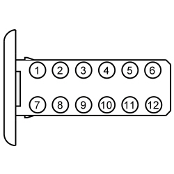
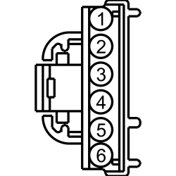

 | Yes
GO to AF6 . No REPAIR the circuit. | ||||||||||||||||||||||||||||||||||||||||||||||||||||||||||||||||
| AF6 CHECK THE MODULE GROUND CIRCUIT FOR CONTINUITY | |||||||||||||||||||||||||||||||||||||||||||||||||||||||||||||||||


 | Yes
For the ACM , GO to AF7 . For the FCDIM , GO to AF8 . For the FCIM , GO to AF9 . For the APIM , GO to AF10 . For the GPSM , GO to AF11 . No REPAIR the circuit. | ||||||||||||||||||||||||||||||||||||||||||||||||||||||||||||||||
| AF7 CHECK FOR CORRECT ACM OPERATION | |||||||||||||||||||||||||||||||||||||||||||||||||||||||||||||||||
| Yes
CHECK OASIS for any applicable TSBs. If a TSB exists for this concern, DISCONTINUE this test and FOLLOW TSB instructions. If no TSBs address this concern, INSTALL a new ACM . REFER to Audio Control Module (ACM) . No The system is operating correctly at this time. The concern may have been caused by module connections. ADDRESS the root cause of any connector or pin issues. | ||||||||||||||||||||||||||||||||||||||||||||||||||||||||||||||||
| AF8 CHECK FOR CORRECT FCDIM OPERATION | |||||||||||||||||||||||||||||||||||||||||||||||||||||||||||||||||
| Yes
CHECK OASIS for any applicable TSBs. If a TSB exists for this concern, DISCONTINUE this test and FOLLOW TSB instructions. If no TSBs address this concern, INSTALL a new FCDIM . REFER to Front Controls/Display Interface Module (FCDIM) . No The system is operating correctly at this time. The concern may have been caused by module connections. ADDRESS the root cause of any connector or pin issues. | ||||||||||||||||||||||||||||||||||||||||||||||||||||||||||||||||
| AF9 CHECK FOR CORRECT FCIM OPERATION | |||||||||||||||||||||||||||||||||||||||||||||||||||||||||||||||||
| Yes
CHECK OASIS for any applicable TSBs. If a TSB exists for this concern, DISCONTINUE this test and FOLLOW TSB instructions. If no TSBs address this concern, INSTALL a new FCIM . REFER to Front Controls Interface Module (FCIM) . No The system is operating correctly at this time. The concern may have been caused by module connections. ADDRESS the root cause of any connector or pin issues. | ||||||||||||||||||||||||||||||||||||||||||||||||||||||||||||||||
| AF10 CHECK FOR CORRECT APIM OPERATION | |||||||||||||||||||||||||||||||||||||||||||||||||||||||||||||||||
| Yes
CHECK OASIS for any applicable TSBs. If a TSB exists for this concern, DISCONTINUE this test and FOLLOW TSB instructions. If no TSBs address this concern, For diagnosing and testing please refer to the on-line Workshop Manual. If you do not have an on-line subscription, go to www.motorcraftservice.com. No The system is operating correctly at this time. The concern may have been caused by module connections. ADDRESS the root cause of any connector or pin issues. | ||||||||||||||||||||||||||||||||||||||||||||||||||||||||||||||||
| AF11 CHECK FOR CORRECT GPSM OPERATION | |||||||||||||||||||||||||||||||||||||||||||||||||||||||||||||||||
| Yes
CHECK OASIS for any applicable TSBs. If a TSB exists for this concern, DISCONTINUE this test and FOLLOW TSB instructions. If no TSBs address this concern, INSTALL a new GPSM . REFER to Global Positioning System Module (GPSM) . No The system is operating correctly at this time. The concern may have been caused by module connections. ADDRESS the root cause of any connector or pin issues. | ||||||||||||||||||||||||||||||||||||||||||||||||||||||||||||||||
Pinpoint Test AG: DTC U3003:17
Diagnostics in this manual assume a certain skill level and knowledge of Ford-specific diagnostic practices. Refer to Diagnostic Methods in Section 100-00 for information about these practices.
DTC Fault Trigger Conditions
| DTC | Description | Fault Trigger Conditions |
|---|---|---|
| U3003:17 | Battery Voltage: Circuit Voltage Above Threshold | Set by the ACM , the FCIM , the FCDIM , the APIM (if equipped) and the GPSM (if equipped) when the supply voltage is more than 15.8 volts for more than 250 milliseconds during normal operation or the self-test. |
| Test Step | Result / Action to Take |
|---|---|
| AG1 CHECK FOR HIGH VOLTAGE DTCs SET IN OTHER MODULES | |
| Yes
REFER to Section 414-00 . No GO to AG2 . |
| AG2 CHECK THE BATTERY VOLTAGE | |
| Yes
REFER to Section 414-00 . No GO to AG3 . |
| AG3 RECHECK FOR DTC U3003:17 | |
| Yes
For the ACM , GO to AG4 . For the FCDIM , GO to AG5 . For the FCIM , GO to AG6 . For the APIM , GO to AG7 . For the GPSM , GO to AG8 . No The system is operating normally at this time. The DTC may have been set previously during battery charging or while jump starting the vehicle. |
| AG4 CHECK FOR CORRECT ACM OPERATION | |
| Yes
CHECK OASIS for any applicable TSBs. If a TSB exists for this concern, DISCONTINUE this test and FOLLOW TSB instructions. If no TSBs address this concern, INSTALL a new ACM . REFER to Audio Control Module (ACM) . No The system is operating correctly at this time. The concern may have been caused by module connections. ADDRESS the root cause of any connector or pin issues. |
| AG5 CHECK FOR CORRECT FCDIM OPERATION | |
| Yes
CHECK OASIS for any applicable TSBs. If a TSB exists for this concern, DISCONTINUE this test and FOLLOW TSB instructions. If no TSBs address this concern, INSTALL a new FCDIM . REFER to Front Controls/Display Interface Module (FCDIM) . No The system is operating correctly at this time. The concern may have been caused by module connections. ADDRESS the root cause of any connector or pin issues. |
| AG6 CHECK FOR CORRECT FCIM OPERATION | |
| Yes
CHECK OASIS for any applicable TSBs. If a TSB exists for this concern, DISCONTINUE this test and FOLLOW TSB instructions. If no TSBs address this concern, INSTALL a new FCIM . REFER to Front Controls Interface Module (FCIM) . No The system is operating correctly at this time. The concern may have been caused by module connections. ADDRESS the root cause of any connector or pin issues. |
| AG7 CHECK FOR CORRECT APIM OPERATION | |
| Yes
CHECK OASIS for any applicable TSBs. If a TSB exists for this concern, DISCONTINUE this test and FOLLOW TSB instructions. If no TSBs address this concern, For diagnosing and testing please refer to the on-line Workshop Manual. If you do not have an on-line subscription, go to www.motorcraftservice.com. No The system is operating correctly at this time. The concern may have been caused by module connections. ADDRESS the root cause of any connector or pin issues. |
| AG8 CHECK FOR CORRECT GPSM OPERATION | |
| Yes
CHECK OASIS for any applicable TSBs. If a TSB exists for this concern, DISCONTINUE this test and FOLLOW TSB instructions. If no TSBs address this concern, INSTALL a new GPSM . REFER to Global Positioning System Module (GPSM) . No The system is operating correctly at this time. The concern may have been caused by module connections. ADDRESS the root cause of any connector or pin issues. |
Pinpoint Test AH: Poor Sound Quality From One Or More Speakers (Not All Speakers)
Diagnostics in this manual assume a certain skill level and knowledge of Ford-specific diagnostic practices. Refer to Diagnostic Methods in Section 100-00 for information about these practices.
Refer to Wiring Diagrams Cell 130 , Audio System/Navigation for schematic and connector information.
The Audio Front Control Module (ACM) sends audio signals to the speakers in the form of AC voltage, resulting in clear audio output.
Inspect around the suspect area for any possible rattle conditions such as:
| Test Step | Result / Action to Take |
|---|---|
| AH1 ISOLATE THE ZONE OF THE POOR SOUND QUALITY | |
| Yes
REPAIR or REPLACE the trim panel(s) as needed. No GO to AH2 . |
| AH2 REMOVE AND INSPECT BEHIND OR UNDERNEATH THE TRIM PANEL(S) IN QUESTION | |
| Yes
REPAIR or REPLACE any loose or broken component or fastener as needed. No GO to AH3 . |
| AH3 CHECK THE SPEAKER IN QUESTION FOR WATER INTRUSION | |
| Yes
VERIFY the watershield is in the correct location, REPAIR or REPLACE any trim, door or speaker seal as required. DRY the speaker in question and TEST the system for normal operation. No GO to AH4 . |
| AH4 ISOLATE SPEAKER TO VERIFY NOISE | |
| Yes
INSTALL a new speaker for the one in question. No LOCATE the source of the noise and REPAIR as needed. |