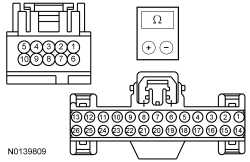
SECTION 417-01: Exterior Lighting
| 2014 Flex Workshop Manual
|
DIAGNOSIS AND TESTING
| Procedure revision date: 05/02/2013
|
Exterior Lighting
Charts
Diagnostics in this manual assume a certain skill level and knowledge of Ford-specific diagnostic practices. Refer to Diagnostic Methods in
Section 100-00
for information about these practices.
Chart
| DTC
| Description
| Action
|
|---|
| B1115:11
| High Mounted Stop Lamp Control: Circuit Short To Ground
| GO to Pinpoint Test J
.
|
| B123A:11
| Left Front Turn Indicator: Circuit Short To Ground
| GO to Pinpoint Test M
.
|
| B123A:15
| Left Front Turn Indicator: Circuit Short To Battery or Open
| GO to Pinpoint Test M
.
|
| B123B:11
| Right Front Turn Indicator: Circuit Short To Ground
| GO to Pinpoint Test M
.
|
| B123B:15
| Right Front Turn Indicator: Circuit Short To Battery or Open
| GO to Pinpoint Test M
.
|
| B1277:11
| Reverse Lamp: Circuit Short To Ground
| GO to Pinpoint Test U
.
|
| B1277:15
| Reverse Lamp: Circuit Short To Battery or Open
| If the reversing lamps are inoperative,
GO to Pinpoint Test U
.
If the reversing lamps are always on,
GO to Pinpoint Test W
.
|
| B132B:11
| Left Stop/Turn Lamp: Circuit Short To Ground
| GO to Pinpoint Test J
.
|
| B132B:15
| Left Stop/Turn Lamp: Circuit Short To Battery or Open
| If the stop/turn lamp is inoperative,
GO to Pinpoint Test J
.
If the stop/turn lamp is always on,
GO to Pinpoint Test K
.
|
| B132C:11
| Right Stop/Turn Lamp: Circuit Short To Ground
| GO to Pinpoint Test J
.
|
| B132C:15
| Right Stop/Turn Lamp: Circuit Short To Battery or Open
| If the stop/turn lamp is inoperative,
GO to Pinpoint Test J
.
If the stop/turn lamp is always on,
GO to Pinpoint Test K
.
|
| B1C98:11
| Left Corner Lamp Circuit: Circuit Short To Ground
| GO to Pinpoint Test M
.
|
| B1C98:15
| Left Corner Lamp Circuit: Circuit Short To Battery or Open
| GO to Pinpoint Test M
.
|
| B1C99:11
| Right Corner Lamp Circuit: Circuit Short To Ground
| GO to Pinpoint Test M
.
|
| B1C99:15
| Right Corner Lamp Circuit: Circuit Short To Battery or Open
| GO to Pinpoint Test M
.
|
| B1A85:11
| Ambient Light Sensor: Circuit Short To Ground
| GO to Pinpoint Test H
.
|
| B1A85:13
| Ambient Light Sensor: Circuit Open
| GO to Pinpoint Test H
.
|
| B1D00:11
| Left Low Beam: Circuit Short To Ground
| GO to Pinpoint Test A
.
|
| B1D00:15
| Left Low Beam: Circuit Short To Battery or Open
| GO to Pinpoint Test A
.
|
| B1D01:11
| Right Low Beam: Circuit Short To Ground
| GO to Pinpoint Test A
.
|
| B1D01:15
| Right Low Beam: Circuit Short To Battery or Open
| GO to Pinpoint Test A
.
|
| B1D02:11
| Left High Beam Circuit: Circuit Short To Ground
| GO to Pinpoint Test B
.
|
| B1D02:15
| Left High Beam Circuit: Circuit Short To Battery or Open
| If the high beams are inoperative,
GO to Pinpoint Test B
.
If the high beams are always on,
GO to Pinpoint Test D
.
|
| B1D03:11
| Right High Beam Circuit: Circuit Short To Ground
| GO to Pinpoint Test B
.
|
| B1D03:15
| Right High Beam Circuit: Circuit Short To Battery or Open
| If the high beams are inoperative,
GO to Pinpoint Test B
.
If the high beams are always on,
GO to Pinpoint Test D
.
|
| B1D35:11
| Hazard Switch: Circuit Short to Ground
| GO to Pinpoint Test N
.
|
| C0040:12
| Brake Pedal Switch "A": Circuit Short To Battery
| GO to Pinpoint Test K
.
|
Chart
Module
Chart
Symptom Charts
Diagnostics in this manual assume a certain skill level and knowledge of Ford-specific diagnostic practices. Refer to Diagnostic Methods in
Section 100-00
for information about these practices.
Symptom Chart: Headlamps
| Condition
| Possible Sources
| Action
|
|---|
- One or both low beams are inoperative
| - Refer to the Diagnostic Routine
| |
- One or both high beams are inoperative
| - Refer to the Diagnostic Routine
| |
- The low beams are on continuously
| - Refer to the Diagnostic Routine
| |
- The high beams are on continuously
| - Refer to the Diagnostic Routine
| |
- The flash-to-pass feature is inoperative
| - Refer to the Diagnostic Routine
| |
Symptom Chart: Daytime Running Lamps (DRL)
| Condition
| Possible Sources
| Action
|
|---|
- The Daytime Running Lamps (DRL) are inoperative
| - Refer to the Diagnostic Routine
| |
Symptom Chart: Autolamps
| Condition
| Possible Sources
| Action
|
|---|
- The autolamps are inoperative
| - Refer to the Diagnostic Routine
| |
- The autolamps are on continuously
| - Refer to the Diagnostic Routine
| |
Symptom Chart: Stoplamps
| Condition
| Possible Sources
| Action
|
|---|
- All the stoplamps are inoperative
| - Refer to the Diagnostic Routine
| |
- One or more stoplamps are inoperative
| - Refer to the Diagnostic Routine
| |
- The stoplamps are on continuously
| - Refer to the Diagnostic Routine
| |
Symptom Chart: Turn Signal And Hazard Lamps
| Condition
| Possible Sources
| Action
|
|---|
- The turn signal lamps flash fast and no bulbs are inoperative
| - NOTE:
LED lamps draw low current compared to an incandescent bulb. The Body Control Module (BCM) can interpret this as a bulb out and fast flashes (bulb outage mode).
Bulb
| - INSTALL correct turn lamp bulbs as necessary.
|
- The turn signal function is inoperative
| - Refer to the Diagnostic Routine
| |
- The turn signal function is always on
| - Refer to the Diagnostic Routine
| - INSTALL a new multifunction switch. REFER to
Section 211-05
. TEST the system for normal operation. If the concern still exists, INSTALL a new
. REFER to
Section 211-05
.
|
- One turn signal lamp is inoperative/always on
| - Refer to the Diagnostic Routine
| |
- The hazard lamp function is inoperative/always on
| - Refer to the Diagnostic Routine
| |
Symptom Chart: Parking, Rear And License Plate Lamps
| Condition
| Possible Sources
| Action
|
|---|
- One or more parking, rear or license plate lamps is inoperative
| - Refer to the Diagnostic Routine
| |
- The parking, rear or license plate lamps are on continuously
| - Refer to the Diagnostic Routine
| |
Symptom Chart: Fog Lamps
| Condition
| Possible Sources
| Action
|
|---|
- Both fog lamps are inoperative
| - Refer to the Diagnostic Routine
| |
- An individual fog lamp is inoperative
| - Refer to the Diagnostic Routine
| |
- The fog lamps are on continuously
| - Refer to the Diagnostic Routine
| |
- The fog lamps on indicator is inoperative
| - Refer to the Diagnostic Routine
| |
Symptom Chart: Reversing Lamps
| Condition
| Possible Sources
| Action
|
|---|
- All the reversing lamps are inoperative
| - Refer to the Diagnostic Routine
| |
- An individual reversing lamp is inoperative
| - Refer to the Diagnostic Routine
| |
- The reversing lamps are on continuously
| - Refer to the Diagnostic Routine
| |
Symptom Chart: Trailer Lamps
| Condition
| Possible Sources
| Action
|
|---|
- All the trailer lamps are inoperative
| - Refer to the Diagnostic Routine
| |
- The trailer stop/turn lamp is inoperative
| - Refer to the Diagnostic Routine
| |
- The trailer parking lamps are inoperative
| - Refer to the Diagnostic Routine
| |
- The trailer reversing lamps are inoperative
| - Refer to the Diagnostic Routine
| |
- The trailer lamps are on continuously
| - Refer to the Diagnostic Routine
| |
- The trailer battery charging is inoperative/does not operate correctly
| - Refer to the Diagnostic Routine
| |
- The trailer electric brakes are inoperative/always applied
| - Refer to the Diagnostic Routine
| |
Pinpoint Tests
Pinpoint Test A: One Or Both Low Beams Are Inoperative
Diagnostic Overview
Diagnostics in this manual assume a certain skill level and knowledge of Ford-specific diagnostic practices. Refer to Diagnostic Methods in
Section 100-00
for information about these practices.
Refer to Wiring Diagrams Cell
85
, Headlamps/Autolamps for schematic and connector information.
Normal Operation and Fault Conditions
Refer to System Operation - Low Beams in
Headlamps
.
Refer to Component Description - Headlamp Assembly in
Headlamps
.
Refer to Component Description - Ballast in
Headlamps
.
DTC Fault Trigger Conditions
| DTC
| Description
| Fault Trigger Conditions
|
|---|
| B1D00:11
| Left Low Beam: Circuit Short To Ground
| Sets when the
detects a short to ground from the LH low beam output circuit.
|
| B1D00:15
| Left Low Beam: Circuit Short To Battery or Open
| Sets when the
detects an open from the LH low beam output circuit.
|
| B1D01:11
| Right Low Beam: Circuit Short To Ground
| Sets when the
detects a short to ground from the RH low beam output circuit.
|
| B1D01:15
| Right Low Beam: Circuit Short To Battery or Open
| Sets when the
detects an open from the RH low beam output circuit.
|
Possible Sources
- fuses 17 (10A) (left low beam) and 16 (10A) (right low beam)
- fuses 57 (20A) (left ballast) and 78 (20A) (right ballast)
- Bulb
- Wiring, terminals or connectors
- Ballast
- Headlamp assembly
PINPOINT TEST A: ONE OR BOTH LOW BEAMS ARE INOPERATIVE
NOTE:
Due to varying wattage ratings and the resulting current draw differences of certain aftermarket halogen headlamp bulbs, the
may activate its short circuit protection strategy, resulting in the low beam output circuit becoming inoperative. Verify the bulbs meet Ford specifications. If the bulbs do not meet Ford specifications, install the correct bulbs. Run the self-test (required to clear certain DTCs and reset the
). Correct any unresolved DTCs. Clear all DTCs. Test the system for normal operation.
| Test Step
| Result / Action to Take
|
|---|
|
A1 CHECK FOR VOLTAGE TO THE HEADLAMP ASSEMBLY
|
|
- Ignition OFF.
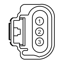
- Disconnect: Inoperative LH Headlamp C1021 or RH Headlamp C1041 (Halogen headlamps).
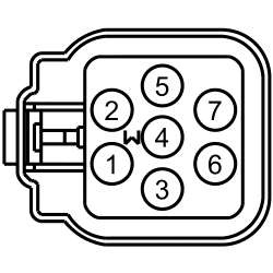
- Disconnect: Inoperative LH Headlamp C1284 or RH Headlamp C1285 (
Headlamps).
- Place the headlamp switch in the headlamps on position.
- For halogen headlamps, measure the
voltage
between:
| Positive Lead
| Negative Lead
| | Pin
| Circuit
| Pin
| Circuit
| | LH Headlamp
| | C1021-1
| CLF04 (BN/BU)
| —
| Ground
| | RH Headlamp
| | C1041-1
| CLF05 (BU/GN)
| —
| Ground
|
 - For
headlamps, measure the
voltage
between:
| Positive Lead
| Negative Lead
| | Pin
| Circuit
| Pin
| Circuit
| | LH Headlamp
| | C1284-2
| CLF04 (BN/BU)
| —
| Ground
| | RH Headlamp
| | C1285-2
| CLF05 (BU/GN)
| —
| Ground
|
 - Is the voltage greater than 11 volts?
| Yes
GO to
A2
.
No
VERIFY the
fuse 17 (10A) (LH low beam) or fuse 16 (10A) (RH low beam) is OK. If OK, GO to
A6
. If not OK, REFER to the Wiring Diagrams manual to identify the possible causes of the circuit short.
|
|
A2 CHECK THE HEADLAMP ASSEMBLY GROUND CIRCUIT FOR AN OPEN
|
|
- For halogen headlamps, measure the
voltage
between:
| Positive Lead
| Negative Lead
| | Pin
| Circuit
| Pin
| Circuit
| | LH Headlamp
| | C1021-1
| CLF04 (BN/BU)
| C1021-2
| GD123 (BK/GY)
| | RH Headlamp
| | C1041-1
| CLF05 (BU/GN)
| C1041-2
| GD120 (BK/GN)
|
 - For
headlamps, measure the
voltage
between:
| Positive Lead
| Negative Lead
| | Pin
| Circuit
| Pin
| Circuit
| | LH Headlamp
| | C1284-2
| CLF04 (BN/BU)
| C1284-6
| GD123 (BK/GY)
| | RH Headlamp
| | C1285-2
| CLF05 (BU/GN)
| C1285-6
| GD120 (BK/GN)
|
 - Is the voltage greater than 11 volts?
| Yes
For halogen headlamps, INSTALL a new headlamp bulb. REFER to
Headlamp Bulb
.
For
headlamps, GO to
A3
.
No
REPAIR the circuit.
|
|
A3 CHECK FOR BALLAST SUPPLY VOLTAGE TO THE HEADLAMP ASSEMBLY
|
|
- Measure the
voltage
between:
| Positive Lead
| Negative Lead
| | Pin
| Circuit
| Pin
| Circuit
| | LH Headlamp
| | C1284-3
| SBB57 (RD)
| —
| Ground
| | RH Headlamp
| | C1285-3
| SBB78 (BN/RD)
| —
| Ground
|
 - Is the voltage greater than 11 volts?
| Yes
GO to
A4
.
No
VERIFY the
fuse 57 (20A) (LH headlamp) or fuse 78 (20A) (RH headlamp) is OK. If OK, REPAIR the affected circuit. If not OK, REFER to the Wiring Diagrams manual to identify the possible causes of the circuit short.
|
|
A4 CHECK THE BALLAST
|
|
- Place the headlamp switch in the off position.
- Substitute a known good ballast.
- Place the headlamp switch in the headlamps on position.
- Does the inoperative headlamp illuminate?
| Yes
REMOVE the known good ballast. INSTALL a new ballast. REFER to
Ballast
.
No
REMOVE the known good ballast. GO to
A5
.
|
|
A5 CHECK THE
BULB
|
|
- Place the headlamp switch in the off position.
- Substitute a known good
bulb.
- Place the headlamp switch in the headlamps on position.
- Does the inoperative headlamp illuminate?
| Yes
REMOVE the known good
bulb. INSTALL a new
bulb. REFER to
Headlamp Bulb
.
No
REMOVE the known good
bulb. REPAIR or INSTALL a new headlamp assembly. REFER to
Headlamp Assembly
.
|
|
A6 REPEAT THE
SELF-TEST AND CHECK FOR VOLTAGE TO THE HEADLAMP
|
|
- Place the headlamp switch in the off position.
- Ignition ON.
- Using a scan tool, clear the DTCs and perform the
self-test.
- Place the headlamp switch in the headlamps on position.
- For halogen headlamps, measure the
voltage
between:
| Positive Lead
| Negative Lead
| | Pin
| Circuit
| Pin
| Circuit
| | LH Headlamp
| | C1021-1
| CLF04 (BN/BU)
| —
| Ground
| | RH Headlamp
| | C1041-1
| CLF05 (BU/GN)
| —
| Ground
|
 - For
headlamps, measure the
voltage
between:
| Positive Lead
| Negative Lead
| | Pin
| Circuit
| Pin
| Circuit
| | LH Headlamp
| | C1284-2
| CLF04 (BN/BU)
| —
| Ground
| | RH Headlamp
| | C1285-2
| CLF05 (BU/GN)
| —
| Ground
|
 - Is the voltage greater than 11 volts?
| Yes
For halogen headlamps, INSTALL a new headlamp bulb. REFER to
Headlamp Bulb
.
For
headlamps, GO to
A7
.
No
GO to
A8
.
|
|
A7 CHECK THE HEADLAMP HARNESS
|
|
- Ignition OFF.
- Place the headlamp switch in the off position.
- Check the headlamp harness for an internal short to the ground circuit.
- Is the headlamp harness OK?
| Yes
INSTALL a new ballast. REFER to
Ballast
.
No
REPAIR or INSTALL a new headlamp assembly. REFER to
Headlamp Assembly
.
|
|
A8 CHECK THE
LOW BEAM VOLTAGE SUPPLY CIRCUIT FOR A SHORT TO GROUND
|
|
- Ignition OFF.
- Place the headlamp switch in the off position.
- Disconnect:
C2280E.
- For halogen headlamps, measure the
resistance
between:
| Positive Lead
| Negative Lead
| | Pin
| Circuit
| Pin
| Circuit
| | LH Headlamp
| | C1021-1
| CLF04 (BN/BU)
| —
| Ground
| | RH Headlamp
| | C1041-1
| CLF05 (BU/GN)
| —
| Ground
|
 - For
headlamps, measure the
resistance
between:
| Positive Lead
| Negative Lead
| | Pin
| Circuit
| Pin
| Circuit
| | LH Headlamp
| | C1284-2
| CLF04 (BN/BU)
| —
| Ground
| | RH Headlamp
| | C1285-2
| CLF05 (BU/GN)
| —
| Ground
|
 - Is the resistance greater than 10,000 ohms?
| Yes
GO to
A9
.
No
REPAIR the circuit.
|
|
A9 CHECK THE
LOW BEAM VOLTAGE SUPPLY CIRCUIT FOR AN OPEN
|
|
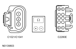
- For halogen headlamps, measure the
resistance
between:
| Positive Lead
| Negative Lead
| | Pin
| Circuit
| Pin
| Circuit
| | LH Headlamp
| | C1021-1
| CLF04 (BN/BU)
| C2280E-2
| CLF04 (BN/BU)
| | RH Headlamp
| | C1041-1
| CLF05 (BU/GN)
| C2280E-1
| CLF05 (BU/GN)
|
 - For
headlamps, measure the
resistance
between:
| Positive Lead
| Negative Lead
| | Pin
| Circuit
| Pin
| Circuit
| | LH Headlamp
| | C1284-2
| CLF04 (BN/BU)
| C2280E-2
| CLF04 (BN/BU)
| | RH Headlamp
| | C1285-2
| CLF05 (BU/GN)
| C2280E-1
| CLF05 (BU/GN)
|
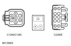 - Is the resistance less than 3 ohms?
| Yes
GO to
A10
.
No
REPAIR the circuit.
|
|
A10 CHECK FOR CORRECT
OPERATION
|
|
- Disconnect and inspect all the
connectors.
- Repair:
- corrosion (install new connector or terminals – clean module pins)
- damaged or bent pins – install new terminals/pins
- pushed-out pins – install new pins as necessary
- Reconnect the
connectors. Make sure they seat and latch correctly.
- Operate the system and determine if the concern is still present.
- Is the concern still present?
| Yes
CHECK On-Line Automotive Service Information System (OASIS) for any applicable TSBs. If a TSB exists for this concern, DISCONTINUE this test and FOLLOW TSB instructions. If no TSBs address this concern, INSTALL a new
. REFER to
Section 419-10
.
No
The system is operating correctly at this time. The concern may have been caused by module connections. ADDRESS the root cause of any connector or pin issues.
|
Pinpoint Test B: One or Both High Beams are Inoperative
Diagnostic Overview
Diagnostics in this manual assume a certain skill level and knowledge of Ford-specific diagnostic practices. Refer to Diagnostic Methods in
Section 100-00
for information about these practices.
Refer to Wiring Diagrams Cell
85
, Headlamps/Autolamps for schematic and connector information.
Normal Operation and Fault Conditions
Refer to System Operation - High Beams in
Headlamps
.
Refer to Component Description - Headlamp Assembly in
Headlamps
.
DTC Fault Trigger Conditions
| DTC
| Description
| Fault Trigger Conditions
|
|---|
| B1D02:11
| Left High Beam Circuit: Circuit Short To Ground
| Sets when the
detects a short to ground from the LH high beam output circuit.
|
| B1D02:15
| Left High Beam Circuit: Circuit Short To Battery or Open
| Sets when the
detects an open from the LH high beam output circuit.
|
| B1D03:11
| Right High Beam Circuit: Circuit Short To Ground
| Sets when the
detects a short to ground from the RH high beam output circuit.
|
| B1D03:15
| Right High Beam Circuit: Circuit Short To Battery or Open
| Sets when the
detects an open from the RH high beam output circuit.
|
Possible Sources
- fuse 39 (15A)
- Wiring, terminals or connectors
- Multifunction switch
- Headlamp assembly
PINPOINT TEST B: ONE OR BOTH HIGH BEAMS ARE INOPERATIVE
| Test Step
| Result / Action to Take
|
|---|
|
B1 CHECK THE LOW BEAM OPERATION
|
|
- Ignition OFF.
- Place the headlamp switch in the headlamps on position and observe the headlamps.
- Place the multifunction switch in the HIGH BEAM position and observe the headlamps.
- Place the multifunction switch in the LOW BEAM position and observe the headlamps.
- Do the low beams illuminate?
| Yes
If an individual high beam is inoperative, GO to
B3
.
If both high beams are inoperative, VERIFY the
fuse 39 (15A) is OK. If OK, GO to
B2
. If not OK, REFER to the Wiring Diagrams manual to identify the possible causes of the circuit short.
No
GO to Pinpoint Test A
.
|
|
B2 CHECK THE MULTIFUNCTION SWITCH INPUT
|
|
- Ignition ON.
- Using a scan tool, view
PIDs.
- Monitor the
HEADLAMP_SW PID while placing the multifunction switch in the flash-to-pass and high beam positions.
- Do the PID states agree with the multifunction switch positions?
| Yes
GO to
B8
.
No
INSTALL a new multifunction switch. REFER to
Section 211-05
.
If the concern still exists, INSTALL an new
. REFER to
Section 211-05
.
|
|
B3 CHECK FOR VOLTAGE TO THE HEADLAMP
|
|
- Place the headlamp switch in the off position.
- Disconnect: Inoperative LH Headlamp C1021 or RH Headlamp C1041 (Halogen headlamps).
- Disconnect: Inoperative LH Headlamp C1284 or RH Headlamp C1285 (
Headlamps).
- Place the headlamp switch in the headlamps on position and the multifunction switch in the HIGH BEAM position.
- For halogen headlamps, measure the
voltage
between:
| Positive Lead
| Negative Lead
| | Pin
| Circuit
| Pin
| Circuit
| | LH Headlamp
| | C1021-3
| CLF02 (GY/BN)
| —
| Ground
| | RH Headlamp
| | C1041-3
| CLF03 (VT/OG)
| —
| Ground
|
 - For
headlamps, measure the
voltage
between:
| Positive Lead
| Negative Lead
| | Pin
| Circuit
| Pin
| Circuit
| | LH Headlamp
| | C1284-1
| CLF02 (GY/BN)
| —
| Ground
| | RH Headlamp
| | C1285-1
| CLF03 (VT/OG)
| —
| Ground
|
 - Is the voltage greater than 11 volts?
| Yes
GO to
B4
.
No
GO to
B5
.
|
|
B4 CHECK THE HEADLAMP GROUND CIRCUIT FOR AN OPEN
|
|
- For halogen headlamps, measure the
voltage
between:
| Positive Lead
| Negative Lead
| | Pin
| Circuit
| Pin
| Circuit
| | LH Headlamp
| | C1021-3
| CLF02 (GY/BN)
| C1021-2
| GD123 (BK/GY)
| | RH Headlamp
| | C1041-3
| CLF03 (VT/OG)
| C1041-2
| GD120 (BK/GN)
|
 - For
headlamps, measure the
voltage
between:
| Positive Lead
| Negative Lead
| | Pin
| Circuit
| Pin
| Circuit
| | LH Headlamp
| | C1284-1
| CLF02 (GY/BN)
| C1284-6
| GD123 (BK/GY)
| | RH Headlamp
| | C1285-1
| CLF03 (VT/OG)
| C1285-6
| GD120 (BK/GN)
|
 - Is the voltage greater than 11 volts?
| Yes
REPAIR or INSTALL a new headlamp assembly. REFER to
Headlamp Assembly
.
No
REPAIR the circuit.
|
|
B5 REPEAT THE ON-DEMAND SELF-TEST AND CHECK FOR VOLTAGE TO THE HEADLAMP
|
|
- Place the headlamp switch in the off position.
- Ignition ON.
- Using a scan tool, clear the DTCs and perform the
self-test.
- Place the headlamp switch in the headlamps on position and the multifunction switch in the HIGH BEAM position.
- For halogen headlamps, measure the
voltage
between:
| Positive Lead
| Negative Lead
| | Pin
| Circuit
| Pin
| Circuit
| | LH Headlamp
| | C1021-3
| CLF02 (GY/BN)
| —
| Ground
| | RH Headlamp
| | C1041-3
| CLF03 (VT/OG)
| —
| Ground
|
 - For
headlamps, measure the
voltage
between:
| Positive Lead
| Negative Lead
| | Pin
| Circuit
| Pin
| Circuit
| | LH Headlamp
| | C1284-1
| CLF02 (GY/BN)
| —
| Ground
| | RH Headlamp
| | C1285-1
| CLF03 (VT/OG)
| —
| Ground
|
 - Is the voltage greater than 11 volts?
| Yes
For halogen headlamps, INSTALL a new headlamp bulb. REFER to
Headlamp Bulb
.
For
headlamps, INSTALL a new headlamp assembly. REFER to
Headlamp Assembly
.
No
GO to
B6
.
|
|
B6 CHECK THE
HIGH BEAM VOLTAGE SUPPLY CIRCUIT FOR A SHORT TO GROUND
|
|
- Ignition OFF.
- Disconnect:
C2280E.
- For halogen headlamps, measure the
resistance
between:
| Positive Lead
| Negative Lead
| | Pin
| Circuit
| Pin
| Circuit
| | LH Headlamp
| | C1021-3
| CLF02 (GY/BN)
| —
| Ground
| | RH Headlamp
| | C1041-3
| CLF03 (VT/OG)
| —
| Ground
|
 - For
headlamps, measure the
resistance
between:
| Positive Lead
| Negative Lead
| | Pin
| Circuit
| Pin
| Circuit
| | LH Headlamp
| | C1284-1
| CLF02 (GY/BN)
| —
| Ground
| | RH Headlamp
| | C1285-1
| CLF03 (VT/OG)
| —
| Ground
|
 - Is the resistance greater than 10,000 ohms?
| Yes
GO to
B7
.
No
REPAIR the circuit.
|
|
B7 CHECK THE
HIGH BEAM VOLTAGE SUPPLY CIRCUIT FOR AN OPEN
|
|
- For halogen headlamps, measure the
resistance
between:
| Positive Lead
| Negative Lead
| | Pin
| Circuit
| Pin
| Circuit
| | LH Headlamp
| | C1021-3
| CLF02 (GY/BN)
| C2280E-8
| CLF02 (GY/BN)
| | RH Headlamp
| | C1041-3
| CLF03 (VT/OG)
| C2280E-7
| CLF03 (VT/OG)
|
 - For
headlamps, measure the
resistance
between:
| Positive Lead
| Negative Lead
| | Pin
| Circuit
| Pin
| Circuit
| | LH Headlamp
| | C1284-1
| CLF02 (GY/BN)
| C2280E-8
| CLF02 (GY/BN)
| | RH Headlamp
| | C1285-1
| CLF03 (VT/OG)
| C2280E-7
| CLF03 (VT/OG)
|
 - Is the resistance less than 3 ohms?
| Yes
GO to
B8
.
No
REPAIR the circuit.
|
|
B8 CHECK FOR CORRECT
OPERATION
|
|
- Disconnect and inspect all the
connectors.
- Repair:
- corrosion (install new connector or terminals – clean module pins)
- damaged or bent pins – install new terminals/pins
- pushed-out pins – install new pins as necessary
- Reconnect the
connectors. Make sure they seat and latch correctly.
- Operate the system and determine if the concern is still present.
- Is the concern still present?
| Yes
CHECK On-Line Automotive Service Information System (OASIS) for any applicable TSBs. If a TSB exists for this concern, DISCONTINUE this test and FOLLOW TSB instructions. If no TSBs address this concern, INSTALL a new
. REFER to
Section 419-10
.
No
The system is operating correctly at this time. The concern may have been caused by module connections. ADDRESS the root cause of any connector or pin issues.
|
Pinpoint Test C: The Low Beams Are On Continuously
Diagnostic Overview
Diagnostics in this manual assume a certain skill level and knowledge of Ford-specific diagnostic practices. Refer to Diagnostic Methods in
Section 100-00
for information about these practices.
Refer to Wiring Diagrams Cell
85
, Headlamps/Autolamps for schematic and connector information.
Normal Operation and Fault Conditions
Refer to System Operation - Low Beams in
Headlamps
.
Refer to Component Description - Ballast in
Headlamps
.
Possible Sources
- Wiring, terminals or connectors
- Headlamp switch
- Headlamp assembly
PINPOINT TEST C: THE LOW BEAMS ARE ON CONTINUOUSLY
| Test Step
| Result / Action to Take
|
|---|
|
C1 CHECK THE COMMUNICATION NETWORK
|
|
- Ignition ON.
- Using a scan tool, perform the network test.
- Does the
pass the network test?
| Yes
GO to
C2
.
No
REFER to
Section 418-00
. The SCCM Does Not Respond To The Scan Tool.
|
|
C2 CHECK FOR LIGHT SENSOR DTCs
|
|
- Review the DTCs recorded from the
self-test.
- Is DTC B1A85:11 or DTC B1A85:13 present?
| Yes
GO to Pinpoint Test H
.
No
GO to
C3
.
|
|
C3 CHECK THE
AUTOLAMP ON REQUEST PID
|
|
- Ignition ON.
- Using a scan tool, view
PIDs.
- Monitor the
headlamp switch PID (EXT_LMP_SW) while placing the headlamp switch in the AUTOLAMPS ON and then OFF position.
- Does the PID agree with the headlamp switch when it is in the AUTOLAMPS ON position and indicate it is not in the AUTOLAMPS ON position when the headlamp switch is in the OFF position?
| Yes
GO to
C4
.
No
GO to Pinpoint Test H
.
|
|
C4 CHECK THE
HEADLAMP SWITCH PIDs
|
|
| Yes
GO to
C9
.
No
GO to
C5
.
|
|
C5 CHECK FOR VOLTAGE TO THE HEADLAMP SWITCH
|
|
- Ignition OFF.
- Disconnect: Headlamp Switch C205.
- Measure the
voltage
between:
| Positive Lead
| Negative Lead
| | Pin
| Circuit
| Pin
| Circuit
| | C205-2
| CLS34 (GY)
| —
| Ground
| | C205-4
| CLF19 (VT/GN)
| —
| Ground
| | C205-6
| CLF23 (WH/VT)
| —
| Ground
| | C205-7
| CLF24 (YE/BU)
| —
| Ground
|
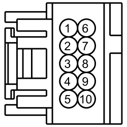 - Are the voltages greater than 5 volts?
| Yes
GO to
C6
.
No
GO to
C7
.
|
|
C6 CHECK THE HEADLAMP SWITCH GROUND CIRCUIT FOR AN OPEN
|
|
- Measure the
voltage
between:
| Positive Lead
| Negative Lead
| | Pin
| Circuit
| Pin
| Circuit
| | C205-6
| CLF23 (WH/VT)
| C205-3
| GD375 (BK/BU)
|
 - Is the voltage greater than 5 volts?
| Yes
INSTALL a new headlamp switch. REFER to
Headlamp Switch
.
No
REPAIR the circuit.
|
|
C7 CHECK THE HEADLAMP SWITCH INPUT CIRCUITS FOR A SHORT TO GROUND
|
|
- Disconnect:
C2414A.
- Measure the
resistance
between:
| Positive Lead
| Negative Lead
| | Pin
| Circuit
| Pin
| Circuit
| | C205-2
| CLS34 (GY)
| —
| Ground
| | C205-4
| CLF19 (VT/GN)
| —
| Ground
| | C205-6
| CLF23 (WH/VT)
| —
| Ground
| | C205-7
| CLF24 (YE/BU)
| —
| Ground
|
 - Are the resistances greater than 10,000 ohms?
| Yes
GO to
C8
.
No
REPAIR the circuit.
|
|
C8 CHECK THE HEADLAMP SWITCH INPUT CIRCUITS FOR AN OPEN
|
|
- Measure the
resistance
between:
| Positive Lead
| Negative Lead
| | Pin
| Circuit
| Pin
| Circuit
| | C205-2
| CLS34 (GY)
| C2414A-6
| CLS34 (GY)
| | C205-4
| CLF19 (VT/GN)
| C2414A-3
| CLF19 (VT/GN)
| | C205-6
| CLF23 (WH/VT)
| C2414A-7
| CLF23 (WH/VT)
| | C205-7
| CLF24 (YE/BU)
| C2414A-4
| CLF24 (YE/BU)
|
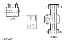 - Are the resistances less than 3 ohms?
| Yes
GO to
C10
.
No
REPAIR the affected circuit.
|
|
C9 CHECK THE
OUTPUT CIRCUITS FOR A SHORT TO VOLTAGE
|
|
- Ignition OFF.
- Disconnect:
C2280E.
- Ignition ON.
- Does the LH or RH headlamp continue to illuminate?
| Yes
REPAIR the affected circuit.
No
GO to
C11
.
|
|
C10 CHECK FOR CORRECT
OPERATION
|
|
- Disconnect and inspect all the
connectors.
- Repair:
- corrosion (install new connector or terminals – clean module pins)
- damaged or bent pins – install new terminals/pins
- pushed-out pins – install new pins as necessary
- Reconnect the
connectors. Make sure they seat and latch correctly.
- Operate the system and determine if the concern is still present.
- Is the concern still present?
| Yes
CHECK On-Line Automotive Service Information System (OASIS) for any applicable TSBs. If a TSB exists for this concern, DISCONTINUE this test and FOLLOW TSB instructions. If no TSBs address this concern, INSTALL a new
. REFER to
Section 211-05
.
No
The system is operating correctly at this time. The concern may have been caused by module connections. ADDRESS the root cause of any connector or pin issues.
|
|
C11 CHECK FOR CORRECT
OPERATION
|
|
- Disconnect and inspect all the
connectors.
- Repair:
- corrosion (install new connector or terminals – clean module pins)
- damaged or bent pins – install new terminals/pins
- pushed-out pins – install new pins as necessary
- Reconnect the
connectors. Make sure they seat and latch correctly.
- Operate the system and determine if the concern is still present.
- Is the concern still present?
| Yes
CHECK On-Line Automotive Service Information System (OASIS) for any applicable
. If a
exists for this concern, DISCONTINUE this test and FOLLOW
instructions. If no
address this concern, INSTALL a new
. REFER to
Section 419-10
.
No
The system is operating correctly at this time. The concern may have been caused by module connections. ADDRESS the root cause of any connector or pin issues.
|
Pinpoint Test D: The High Beams Are On Continuously
Diagnostic Overview
Diagnostics in this manual assume a certain skill level and knowledge of Ford-specific diagnostic practices. Refer to Diagnostic Methods in
Section 100-00
for information about these practices.
Refer to Wiring Diagrams Cell
85
, Headlamps/Autolamps for schematic and connector information.
Normal Operation and Fault Conditions
Refer to System Operation - High Beams in
Headlamps
.
Refer to Component Description - Headlamp Assembly in
Headlamps
.
DTC Fault Trigger Conditions
| DTC
| Description
| Fault Trigger Conditions
|
|---|
| B1007:09
| High-Beam Headlamp Switch: Component Failure
| Sets when the
detects a fault from the multifunction switch input.
|
| B1D02:15
| Left High Beam Circuit: Circuit Short To Battery or Open
| Sets the
detects a short to voltage from the LH high beam output circuit.
|
| B1D03:15
| Right High Beam Circuit: Circuit Short To Battery or Open
| Sets when the
detects a short to voltage from the RH high beam output circuit.
|
Possible Sources
- Wiring, terminals or connectors
- Multifunction switch
- Headlamp assembly
PINPOINT TEST D: THE HIGH BEAMS ARE ON CONTINUOUSLY
| Test Step
| Result / Action to Take
|
|---|
|
D1 CHECK THE MULTIFUNCTION SWITCH INPUT
|
|
- Ignition ON.
- Using a scan tool, view
PIDs.
- Monitor the
FLASH-to-PASS and HIGH_BEAM_SW PIDs while placing the multifunction switch in the flash-to-pass, high beam and rest positions.
- Do the PID values agree with the multifunction switch position?
| Yes
GO to
D2
.
No
INSTALL a new multifunction switch. REFER to
Section 211-05
.
If the concern still exists, INSTALL a new
. REFER to
Section 211-05
.
|
|
D2 CHECK THE HIGH BEAM VOLTAGE SUPPLY CIRCUIT FOR VOLTAGE
|
|
- Ignition OFF.
- Disconnect: Incorrectly Operating LH Headlamp C1021 or RH Headlamp C1041 (Halogen headlamps).
- Disconnect: Incorrectly Operating LH Headlamp C1284 or RH Headlamp C1285 (
Headlamps).
- Ignition ON.
- Make sure the multifunction switch in the rest position.
- For halogen headlamps, measure the
voltage
between:
| Positive Lead
| Negative Lead
| | Pin
| Circuit
| Pin
| Circuit
| | LH Headlamp
| | C1021-3
| CLF02 (GY/BN)
| —
| Ground
| | RH Headlamp
| | C1041-3
| CLF03 (VT/OG)
| —
| Ground
|
 - For
headlamps, measure the
voltage
between:
| Positive Lead
| Negative Lead
| | Pin
| Circuit
| Pin
| Circuit
| | LH Headlamp
| | C1284-1
| CLF02 (GY/BN)
| —
| Ground
| | RH Headlamp
| | C1285-1
| CLF03 (VT/OG)
| —
| Ground
|
 - Is any voltage present?
| Yes
GO to
D3
.
No
INSTALL a new headlamp assembly. REFER to
Headlamp Assembly
.
|
|
D3 CHECK THE
HIGH BEAM OUTPUT CIRCUIT FOR A SHORT TO VOLTAGE
|
|
- Ignition OFF.
- Disconnect:
C2280E.
- Ignition ON.
- For halogen headlamps, measure the
voltage
between:
| Positive Lead
| Negative Lead
| | Pin
| Circuit
| Pin
| Circuit
| | LH Headlamp
| | C1021-3
| CLF02 (GY/BN)
| —
| Ground
| | RH Headlamp
| | C1041-3
| CLF03 (VT/OG)
| —
| Ground
|
 - For
headlamps, measure the
voltage
between:
| Positive Lead
| Negative Lead
| | Pin
| Circuit
| Pin
| Circuit
| | LH Headlamp
| | C1284-1
| CLF02 (GY/BN)
| —
| Ground
| | RH Headlamp
| | C1285-1
| CLF03 (VT/OG)
| —
| Ground
|
 - Is any voltage present?
| Yes
REPAIR the circuit.
No
GO to
D4
.
|
|
D4 CHECK FOR CORRECT
OPERATION
|
|
- Disconnect and inspect all the
connectors.
- Repair:
- corrosion (install new connector or terminals – clean module pins)
- damaged or bent pins – install new terminals/pins
- pushed-out pins – install new pins as necessary
- Reconnect the
connectors. Make sure they seat and latch correctly.
- Operate the system and determine if the concern is still present.
- Is the concern still present?
| Yes
CHECK On-Line Automotive Service Information System (OASIS) for any applicable TSBs. If a TSB exists for this concern, DISCONTINUE this test and FOLLOW TSB instructions. If no TSBs address this concern, INSTALL a new
. REFER to
Section 419-10
.
No
The system is operating correctly at this time. The concern may have been caused by module connections. ADDRESS the root cause of any connector or pin issues.
|
Pinpoint Test E: The Flash-To-Pass Feature Is Inoperative
Diagnostic Overview
Diagnostics in this manual assume a certain skill level and knowledge of Ford-specific diagnostic practices. Refer to Diagnostic Methods in
Section 100-00
for information about these practices.
Normal Operation and Fault Conditions
Refer to System Operation - Flash-To-Pass in
Headlamps
.
Possible Sources
- Multifunction switch
PINPOINT TEST E: THE FLASH-TO-PASS FEATURE IS INOPERATIVE
| Test Step
| Result / Action to Take
|
|---|
|
E1 VERIFY THE HIGH BEAM HEADLAMP OPERATION
|
|
- Ignition ON.
- Place the headlamp switch in the headlamps on position.
- Place the multifunction switch in the HIGH BEAM position while observing the headlamps.
- Do the high beam headlamps illuminate?
| Yes
INSTALL a new multifunction switch. REFER to
Section 211-05
.
If the concern still exists, INSTALL a new
. REFER to
Section 211-05
.
No
GO to Pinpoint Test B
.
|
Pinpoint Test F: The Daytime Running Lamps (DRL) Are Inoperative
Diagnostic Overview
Diagnostics in this manual assume a certain skill level and knowledge of Ford-specific diagnostic practices. Refer to Diagnostic Methods in
Section 100-00
for information about these practices.
Normal Operation and Fault Conditions
Refer to System Operation -
in
Daytime Running Lamps (DRL)
.
Possible Sources
- Exterior lighting system input/output
- Transmission gear input
PINPOINT TEST F: THE
ARE INOPERATIVE
| Test Step
| Result / Action to Take
|
|---|
|
F1 CHECK THE OPERATION OF THE HEADLAMPS AND FOG LAMPS
|
|
- Ignition OFF.
- Place the headlamp switch in the ON position and activate the fog lamps.
- Do the headlamps and fog lamps operate correctly?
| Yes
GO to
F2
.
No
GO to
Symptom Chart - : Headlamps
or GO to
Symptom Chart - : Fog Lamps
.
|
|
F2 VERIFY THE
OPERATION
|
|
- Place the headlamp switch in the off position and deactivate the hazard lamp function.
- Ignition ON.
- Place the gear selector lever in any gear other than PARK (P).
- Are the
illuminated?
| Yes
The system is operating correctly. INFORM the customer of the conditions required for the
to operate correctly.
No
GO to
F3
.
|
|
F3 CHECK THE TRANSMISSION GEAR INPUT
|
|
- Using a scan tool, view PCM PIDs.
- Monitor the PCM Transmission Range (TR) PID while placing the gear selector lever through all its positions.
- Does the PID agree with the gear selection?
| Yes
INSTALL a new
. REFER to
Section 419-10
.
No
REFER to
Section 307-01
to diagnose the transmission range input.
|
Pinpoint Test G: The Autolamps Are Inoperative
Diagnostic Overview
Diagnostics in this manual assume a certain skill level and knowledge of Ford-specific diagnostic practices. Refer to Diagnostic Methods in
Section 100-00
for information about these practices.
Refer to Wiring Diagrams Cell
85
, Headlamps/Autolamps for schematic and connector information.
Normal Operation and Fault Conditions
Refer to System Operation - Autolamps in
Autolamps
.
Refer to Component Description - Light Sensor in
Autolamps
.
Possible Sources
- Light sensor
PINPOINT TEST G: THE AUTOLAMPS ARE INOPERATIVE
| Test Step
| Result / Action to Take
|
|---|
|
G1 CHECK THE MANUAL HEADLAMP OPERATION
|
|
- Place the headlamp switch in the headlamps ON and OFF positions.
- Do the headlamps operate correctly?
| Yes
GO to
G2
.
No
REFER to Symptom Chart: Headlamps in this section.
|
|
G2 CHECK FOR VOLTAGE TO THE LIGHT SENSOR
|
|
- Ignition OFF.
- Disconnect: Light Sensor C286 (
).
- Disconnect: Light Sensor C287 (
).
- Ignition ON.
- Place the headlamp switch in the autolamps on position.
- Measure the
voltage
between:
| Positive Lead
| Negative Lead
| | Pin
| Circuit
| Pin
| Circuit
| | | C286-2
| VLF14 (BU)
| —
| Ground
| | | C287-2
| VLF14 (BU/BN)
| —
| Ground
|
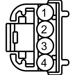 - Is the voltage approximately 5 volts?
| Yes
INSTALL a new light sensor. REFER to
Light Sensor
.
No
GO to
G3
.
|
|
G3 CHECK FOR CORRECT
OPERATION
|
|
- Disconnect and inspect all the
connectors.
- Repair:
- corrosion (install new connector or terminals – clean module pins)
- damaged or bent pins – install new terminals/pins
- pushed-out pins – install new pins as necessary
- Reconnect the
connectors. Make sure they seat and latch correctly.
- Operate the system and determine if the concern is still present.
- Is the concern still present?
| Yes
CHECK On-Line Automotive Service Information System (OASIS) for any applicable TSBs. If a TSB exists for this concern, DISCONTINUE this test and FOLLOW TSB instructions. If no TSBs address this concern, INSTALL a new
. REFER to
Section 419-10
.
No
The system is operating correctly at this time. The concern may have been caused by module connections. ADDRESS the root cause of any connector or pin issues.
|
Pinpoint Test H: The Autolamps Are On Continuously
Diagnostic Overview
Diagnostics in this manual assume a certain skill level and knowledge of Ford-specific diagnostic practices. Refer to Diagnostic Methods in
Section 100-00
for information about these practices.
Refer to Wiring Diagrams Cell
85
, Headlamps/Autolamps for schematic and connector information.
Normal Operation and Fault Conditions
Refer to System Operation - Autolamps in
Autolamps
.
Refer to Component Description - Light Sensor in
Autolamps
.
DTC Fault Trigger Conditions
| DTC
| Description
| Fault Trigger Conditions
|
|---|
| B1A85:11
| Ambient Light Sensor: Circuit Short To Ground
| Sets when the
detects a short to ground from the light sensor input circuit.
|
| B1A85:13
| Ambient Light Sensor: Circuit Open
| Sets when the
detects an open or short to voltage from the light sensor input circuit.
|
Possible Sources
- Wiring, terminals or connectors
- Light sensor
- Headlamp switch
PINPOINT TEST H: THE AUTOLAMPS ARE ON CONTINUOUSLY
| Test Step
| Result / Action to Take
|
|---|
|
H1 CHECK THE
HEADLAMP SWITCH PIDs
|
|
| Yes
GO to
H5
.
No
GO to
H2
.
|
|
H2 CHECK FOR VOLTAGE TO THE HEADLAMP SWITCH
|
|
- Ignition OFF.
- Disconnect: Headlamp Switch C205.
- Measure the
voltage
between:
| Positive Lead
| Negative Lead
| | Pin
| Circuit
| Pin
| Circuit
| | C205-4
| CLF19 (VT/GN)
| —
| Ground
|
 - Is the voltage greater than 5 volts?
| Yes
INSTALL a new headlamp switch. REFER to
Headlamp Switch
.
No
GO to
H3
.
|
|
H3 CHECK AUTOLAMPS REQUEST INPUT CIRCUIT FOR A SHORT TO GROUND
|
|
- Disconnect:
C2414A.
- Measure the
resistance
between:
| Positive Lead
| Negative Lead
| | Pin
| Circuit
| Pin
| Circuit
| | C205-4
| CLF19 (VT/GN)
| —
| Ground
|
 - Is the resistance greater than 10,000 ohms?
| Yes
GO to
H4
.
No
REPAIR the circuit.
|
|
H4 CHECK THE AUTOLAMPS REQUEST INPUT CIRCUIT FOR AN OPEN
|
|
- Measure the
resistance
between:
| Positive Lead
| Negative Lead
| | Pin
| Circuit
| Pin
| Circuit
| | C205-4
| CLF19 (VT/GN)
| C2414A-3
| CLF19 (VT/GN)
|
 - Is the resistance less than 3 ohms?
| Yes
GO to
H14
.
No
REPAIR the circuit.
|
|
H5 CHECK THE
HEADLAMP SWITCH PIDs
|
|
| Yes
GO to
H6
.
No
GO to Pinpoint Test C
.
|
|
H6 USE THE RECORDED DTCs FROM THE
SELF-TEST
|
|
- Check the recorded results from the
self-test.
- Is DTC B1A85:13 or DTC B1A85:11 present?
| Yes
For DTC B1A85:13, GO to
H8
.
For DTC B1A85:11, GO to
H12
.
No
GO to
H7
.
|
|
H7 CHECK FOR VOLTAGE TO THE LIGHT SENSOR (NO DTC)
|
|
- Ignition OFF.
- Disconnect: Light Sensor C286 (
).
- Disconnect: Light Sensor C287 (
).
- Ignition ON.
- Place the headlamp switch in the autolamps on position.
- Measure the
voltage
between:
| Positive Lead
| Negative Lead
| | Pin
| Circuit
| Pin
| Circuit
| | | C286-2
| VLF14 (BU)
| —
| Ground
| | | C287-2
| VLF14 (BU/BN)
| —
| Ground
|
 - Is the voltage approximately 5 volts?
| Yes
INSTALL a new light sensor. REFER to
Light Sensor
.
No
GO to
H15
.
|
|
H8 CHECK FOR VOLTAGE TO THE LIGHT SENSOR (DTC B1A85:13)
|
|
- Ignition OFF.
- Disconnect: Light Sensor C286 (
).
- Disconnect: Light Sensor C287 (
).
- Ignition ON.
- Place the headlamp switch in the autolamps on position.
- Measure the
voltage
between:
| Positive Lead
| Negative Lead
| | Pin
| Circuit
| Pin
| Circuit
| | | C286-2
| VLF14 (BU)
| —
| Ground
| | | C287-2
| VLF14 (BU/BN)
| —
| Ground
|
 - Is the voltage approximately 5 volts?
| Yes
GO to
H11
.
No
GO to
H9
.
|
|
H9 CHECK THE LIGHT SENSOR INPUT CIRCUIT FOR A SHORT TO VOLTAGE
|
|
- Ignition OFF.
- Disconnect:
C2280B.
- Ignition ON.
- Measure the
voltage
between:
| Positive Lead
| Negative Lead
| | Pin
| Circuit
| Pin
| Circuit
| | | C286-2
| VLF14 (BU)
| —
| Ground
| | | C287-2
| VLF14 (BU/BN)
| —
| Ground
|
 - Is any voltage present?
| Yes
REPAIR the circuit.
No
GO to
H10
.
|
|
H10 CHECK THE LIGHT SENSOR INPUT CIRCUIT FOR AN OPEN
|
|
- Ignition OFF.
- Measure the
resistance
between:
| Positive Lead
| Negative Lead
| | Pin
| Circuit
| Pin
| Circuit
| |
| | C286-2
| VLF14 (BU)
| C2280B-30
| VLF14 (BU)
| |
| | C287-2
| VLF14 (BU/BN)
| C2280B-30
| VLF14 (BU/BN)
|
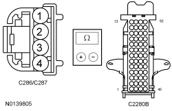 - Is the resistance less than 3 ohms?
| Yes
GO to
H15
.
No
REPAIR the circuit.
|
|
H11 CHECK THE LIGHT SENSOR GROUND CIRCUIT FOR AN OPEN
|
|
- Measure the
voltage
between:
| Positive Lead
| Negative Lead
| | Pin
| Circuit
| Pin
| Circuit
| |
| | C286-2
| VLF14 (BU)
| C286-4
| GD374 (BK/WH)
| |
| | C287-2
| VLF14 (BU/BN)
| C287-4
| GD374 (BK/WH)
|
 - Is the voltage approximately 5 volts?
| Yes
INSTALL a new light sensor. REFER to
Light Sensor
.
No
REPAIR the circuit.
|
|
H12 CHECK FOR VOLTAGE TO THE LIGHT SENSOR (DTC B1A85:11)
|
|
- Ignition OFF.
- Disconnect: Light Sensor C286 (
).
- Disconnect: Light Sensor C287 (
).
- Ignition ON.
- Place the headlamp switch in the autolamps on position.
- Measure the
voltage
between:
| Positive Lead
| Negative Lead
| | Pin
| Circuit
| Pin
| Circuit
| |
| | C286-2
| VLF14 (BU)
| —
| Ground
| |
| | C287-2
| VLF14 (BU/BN)
| —
| Ground
|
 - Is the voltage approximately 5 volts?
| Yes
INSTALL a new light sensor. REFER to
Light Sensor
.
No
GO to
H13
.
|
|
H13 CHECK THE LIGHT SENSOR INPUT CIRCUIT FOR A SHORT TO GROUND
|
|
- Ignition OFF.
- Disconnect:
C2280B.
- Measure the
resistance
between:
| Positive Lead
| Negative Lead
| | Pin
| Circuit
| Pin
| Circuit
| |
| | C286-2
| VLF14 (BU)
| —
| Ground
| |
| | C287-2
| VLF14 (BU/BN)
| —
| Ground
|
 - Is the resistance greater than 10,000 ohms?
| Yes
GO to
H15
.
No
REPAIR the circuit.
|
|
H14 CHECK FOR CORRECT
OPERATION
|
|
- Disconnect and inspect all the
connectors.
- Repair:
- corrosion (install new connector or terminals – clean module pins)
- damaged or bent pins – install new terminals/pins
- pushed-out pins – install new pins as necessary
- Reconnect the
connectors. Make sure they seat and latch correctly.
- Operate the system and determine if the concern is still present.
- Is the concern still present?
| Yes
CHECK On-Line Automotive Service Information System (OASIS) for any applicable TSBs. If a TSB exists for this concern, DISCONTINUE this test and FOLLOW TSB instructions. If no TSBs address this concern, INSTALL a new
. REFER to
Section 211-05
.
No
The system is operating correctly at this time. The concern may have been caused by module connections. ADDRESS the root cause of any connector or pin issues.
|
|
H15 CHECK FOR CORRECT
OPERATION
|
|
- Disconnect and inspect all the
connectors.
- Repair:
- corrosion (install new connector or terminals – clean module pins)
- damaged or bent pins – install new terminals/pins
- pushed-out pins – install new pins as necessary
- Reconnect the
connectors. Make sure they seat and latch correctly.
- Operate the system and determine if the concern is still present.
- Is the concern still present?
| Yes
CHECK On-Line Automotive Service Information System (OASIS) for any applicable TSBs. If a TSB exists for this concern, DISCONTINUE this test and FOLLOW TSB instructions. If no TSBs address this concern, INSTALL a new
. REFER to
Section 419-10
.
No
The system is operating correctly at this time. The concern may have been caused by module connections. ADDRESS the root cause of any connector or pin issues.
|
Pinpoint Test I: All The Stoplamps Are Inoperative
Diagnostic Overview
Diagnostics in this manual assume a certain skill level and knowledge of Ford-specific diagnostic practices. Refer to Diagnostic Methods in
Section 100-00
for information about these practices.
Refer to Wiring Diagrams Cell
90
, Turn Signal/Stop/Hazard Lamps for schematic and connector information.
Normal Operation and Fault Conditions
Refer to System Operation - Stoplamps in
Stoplamps
.
Refer to Component Description - Stoplamp Switch in
Stoplamps
.
Possible Sources
- fuse 15 (15A) (stoplamps)
- fuse 59 (10A) (stoplamp switch)
- Wiring, terminals or connectors
- Stoplamp switch
PINPOINT TEST I: ALL THE STOPLAMPS ARE INOPERATIVE
| Test Step
| Result / Action to Take
|
|---|
|
I1 CHECK THE BRAKE SWITCH 2
PID
|
|
- Ignition ON.
- Using a scan tool, view
PIDs.
- Monitor the
BOO_2 PID while pressing the brake pedal.
- Does the PID read On while the brake pedal pressed?
| Yes
GO to
I2
.
No
GO to
I5
.
|
|
I2 CHECK THE STOPLAMP SWITCH VOLTAGE SUPPLY CIRCUIT FOR AN OPEN
|
|
- Ignition OFF.
- Disconnect: Stoplamp Switch C278.
- Measure the
voltage
between:
| Positive Lead
| Negative Lead
| | Pin
| Circuit
| Pin
| Circuit
| | C278-1
| SBB59 (BU/RD)
| —
| Ground
|
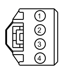 - Is the voltage greater than 11 volts?
| Yes
GO to
I3
.
No
VERIFY the
fuse 59 (10A) is OK. If OK, REPAIR the circuit. If not OK, REFER to the Wiring Diagrams manual to identify the possible causes of the circuit short.
|
|
I3 BYPASS THE STOPLAMP SWITCH
|
|
- Connect a
fused jumper wire
between:
| Lead 1
| Lead 2
| | Pin
| Circuit
| Pin
| Circuit
| | C278-1
| SBB59 (BU/RD)
| C278-4
| CCB08 (VT/WH)
|
 - Do the stoplamps illuminate?
| Yes
REMOVE the jumper wire. INSTALL a new stoplamp switch. REFER to
Stoplamp Switch
.
No
LEAVE the jumper wire connected. GO to
I4
.
|
|
I4 CHECK THE STOPLAMP SWITCH SIGNAL TO THE
|
|
- Disconnect:
C2280B.
- Measure the
voltage
between:
| Positive Lead
| Negative Lead
| | Pin
| Circuit
| Pin
| Circuit
| | C2280B-28
| CCB08 (VT/WH)
| —
| Ground
|
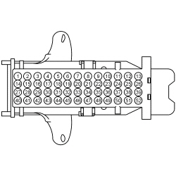 - Is the voltage greater than 11 volts?
| Yes
REMOVE the jumper wire. GO to
I5
.
No
REMOVE the jumper wire. REPAIR the stoplamp switch output circuit for an open.
|
|
I5 CHECK FOR CORRECT
OPERATION
|
|
- Disconnect and inspect all the
connectors.
- Repair:
- corrosion (install new connector or terminals – clean module pins)
- damaged or bent pins – install new terminals/pins
- pushed-out pins – install new pins as necessary
- Reconnect the
connectors. Make sure they seat and latch correctly.
- Operate the system and determine if the concern is still present.
- Is the concern still present?
| Yes
CHECK On-Line Automotive Service Information System (OASIS) for any applicable TSBs. If a TSB exists for this concern, DISCONTINUE this test and FOLLOW TSB instructions. If no TSBs address this concern, INSTALL a new
. REFER to
Section 419-10
.
No
The system is operating correctly at this time. The concern may have been caused by module connections. ADDRESS the root cause of any connector or pin issues.
|
Pinpoint Test J: One Or More Stoplamps Are Inoperative
Diagnostic Overview
Diagnostics in this manual assume a certain skill level and knowledge of Ford-specific diagnostic practices. Refer to Diagnostic Methods in
Section 100-00
for information about these practices.
Refer to Wiring Diagrams Cell
90
, Turn Signal/Stop/Hazard Lamps for schematic and connector information.
Normal Operation and Fault Conditions
Refer to System Operation - Stoplamps in
Stoplamps
.
DTC Fault Trigger Conditions
| DTC
| Description
| Fault Trigger Conditions
|
|---|
| B1115:11
| High Mounted Stop Lamp Control: Circuit Short To Ground
| Sets when the
detects a short to ground from the high mounted stoplamp voltage supply circuit.
|
| B132B:11
| Left Stop/Turn Lamp: Circuit Short To Ground
| Sets when the
detects a short to ground from the left rear stop/turn lamp voltage supply circuit.
|
| B132B:15
| Left Stop/Turn Lamp: Circuit Short To Battery or Open
| Sets when the
detects an open or short to voltage from the left rear stop/turn lamp voltage supply circuit.
|
| B132C:11
| Right Stop/Turn Lamp: Circuit Short To Ground
| Sets when the
detects a short to ground from the right rear stop/turn lamp voltage supply circuit.
|
| B132C:15
| Right Stop/Turn Lamp: Circuit Short To Battery or Open
| Sets when the
detects an open or short to voltage from the right rear stop/turn lamp voltage supply circuit.
|
Possible Sources
- Wiring, terminals or connectors
- Bulb socket
- Rear lamp assembly
- High mounted stoplamp
PINPOINT TEST J: ONE OR MORE STOPLAMPS ARE INOPERATIVE
| Test Step
| Result / Action to Take
|
|---|
|
J1 DETERMINE THE INOPERATIVE STOPLAMP
|
|
- Ignition OFF.
- Apply the brake pedal and observe the stoplamps.
- Are all the stoplamps inoperative?
| Yes
GO to Pinpoint Test I
.
No
For the high mounted stoplamp, GO to
J2
.
If an individual rear stoplamp is inoperative, GO to
J4
.
|
|
J2 CHECK THE HIGH MOUNTED STOPLAMP VOLTAGE SUPPLY CIRCUIT FOR AN OPEN
|
|
- Disconnect: High Mounted Stoplamp C904.
- While applying the brake pedal, measure the
voltage
between:
| Positive Lead
| Negative Lead
| | Pin
| Circuit
| Pin
| Circuit
| | C904-1
| CLS17 (YE/GY)
| —
| Ground
|
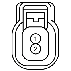 - Is the voltage greater than 11 volts?
| Yes
GO to
J3
.
No
REPAIR the circuit.
|
|
J3 CHECK THE HIGH MOUNTED STOPLAMP GROUND CIRCUIT FOR AN OPEN
|
|
- While applying the brake pedal, measure the
voltage
between:
| Positive Lead
| Negative Lead
| | Pin
| Circuit
| Pin
| Circuit
| | C904-1
| CLS17 (YE/GY)
| C904-2
| GD349 (BK/GY)
|
 - Is the voltage greater than 11 volts?
| Yes
INSTALL a new high mounted stoplamp. REFER to
High Mounted Stoplamp
.
No
REPAIR the circuit.
|
|
J4 CHECK FOR VOLTAGE TO THE REAR LAMP ASSEMBLY
|
|
- Disconnect: Inoperative LH Rear Lamp C498 or RH Rear Lamp C499.
- While applying the brake pedal, measure the
voltage
between:
| Positive Lead
| Negative Lead
| | Pin
| Circuit
| Pin
| Circuit
| | LH Rear Lamp
| | C498-3
| CLS18 (GY/BN)
| —
| Ground
| | RH Rear Lamp
| | C499-3
| CLS19 (VT/OG)
| —
| Ground
|
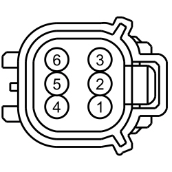 - Is the voltage greater than 11 volts?
| Yes
GO to
J5
.
No
VERIFY the
fuse 14 (15A) (LH stoplamp) or fuse 13 (15A) (RH stoplamp) is OK. If OK, GO to
J7
. If not OK, REFER to the Wiring Diagrams manual to identify the possible causes of the circuit short.
|
|
J5 CHECK THE BULB REAR LAMP ASSEMBLY GROUND CIRCUIT FOR AN OPEN
|
|
- While applying the brake pedal, measure the
voltage
between:
| Positive Lead
| Negative Lead
| | Pin
| Circuit
| Pin
| Circuit
| | LH Rear Lamp
| | C498-3
| CLS18 (GY/BN)
| C498-1
| GD351 (BK/GN)
| | RH Rear Lamp
| | C499-3
| CLS19 (VT/OG)
| C499-1
| GD349 (BK/GY)
|
 - Is the voltage greater than 11 volts?
| Yes
GO to
J6
.
No
REPAIR the circuit
|
|
J6 CHECK THE REAR LAMP JUMPER HARNESS FOR AN OPEN CIRCUIT
|
|
- Inspect the rear lamp jumper harness for an open circuit and shorts.
- Is the rear lamp jumper harness OK?
| Yes
INSTALL a new rear stoplamp bulb socket.
No
REPAIR or INSTALL a new rear lamp jumper harness.
|
|
J7 CARRY OUT THE
ON-DEMAND SELF-TEST AND RECHECK FOR VOLTAGE TO THE REAR STOPLAMP
|
|
- Ignition ON.
- Using a scan tool, clear the DTCs and repeat the
self-test.
- While applying the brake pedal, measure the
voltage
between:
| Positive Lead
| Negative Lead
| | Pin
| Circuit
| Pin
| Circuit
| | LH Rear Lamp
| | C498-3
| CLS18 (GY/BN)
| —
| Ground
| | RH Rear Lamp
| | C499-3
| CLS19 (VT/OG)
| —
| Ground
|
 - Is the voltage greater than 11 volts?
| Yes
GO to
J8
.
No
GO to
J9
.
|
|
J8 CHECK THE REAR LAMP JUMPER HARNESS FOR A SHORTED CIRCUIT
|
|
- Inspect the rear lamp jumper harness for a shorted circuit.
- Is the rear lamp jumper harness OK?
| Yes
INSTALL a new rear stoplamp bulb socket.
No
REPAIR or INSTALL a new rear lamp jumper harness.
|
|
J9 CHECK THE REAR STOPLAMP VOLTAGE SUPPLY CIRCUIT FOR A SHORT TO GROUND
|
|
- Ignition OFF.
- Disconnect:
C2280D.
- Measure the
resistance
between:
| Positive Lead
| Negative Lead
| | Pin
| Circuit
| Pin
| Circuit
| | LH Rear Lamp Inoperative
| | C2280D-12
| CLS18 (GY/BN)
| —
| Ground
| | RH Rear Lamp Inoperative
| | C2280D-15
| CLS19 (VT/OG)
| —
| Ground
|
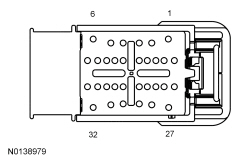 - Is the resistance greater than 10,000 ohms?
| Yes
GO to
J10
.
No
REPAIR the circuit.
|
|
J10 CHECK THE REAR STOPLAMP VOLTAGE SUPPLY CIRCUIT FOR AN OPEN
|
|
- Measure the
resistance
between:
| Positive Lead
| Negative Lead
| | Pin
| Circuit
| Pin
| Circuit
| | LH Rear Lamp
| | C498-3
| CLS18 (GY/BN)
| C2280D-12
| CLS18 (GY/BN)
| | RH Rear Lamp
| | C499-3
| CLS19 (VT/OG)
| C2280D-15
| CLS19 (VT/OG)
|
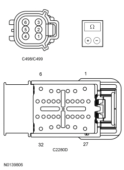 - Is the resistance less than 3 ohms?
| Yes
GO to
J11
.
No
REPAIR the circuit.
|
|
J11 CHECK FOR CORRECT
OPERATION
|
|
- Disconnect and inspect all the
connectors.
- Repair:
- corrosion (install new connector or terminals – clean module pins)
- damaged or bent pins – install new terminals/pins
- pushed-out pins – install new pins as necessary
- Reconnect the
connectors. Make sure they seat and latch correctly.
- Operate the system and determine if the concern is still present.
- Is the concern still present?
| Yes
CHECK On-Line Automotive Service Information System (OASIS) for any applicable TSBs. If a TSB exists for this concern, DISCONTINUE this test and FOLLOW TSB instructions. If no TSBs address this concern, INSTALL a new
. REFER to
Section 419-10
.
No
The system is operating correctly at this time. The concern may have been caused by module connections. ADDRESS the root cause of any connector or pin issues.
|
Pinpoint Test K: The Stoplamps Are On Continuously
Diagnostic Overview
Diagnostics in this manual assume a certain skill level and knowledge of Ford-specific diagnostic practices. Refer to Diagnostic Methods in
Section 100-00
for information about these practices.
Refer to Wiring Diagrams Cell
90
, Turn Signal/Stop/Hazard Lamps for schematic and connector information.
Normal Operation and Fault Conditions
Refer to System Operation - Stoplamps in
Stoplamps
.
Refer to Component Description - Stoplamp Switch in
Stoplamps
.
DTC Fault Trigger Conditions
| DTC
| Description
| Fault Trigger Conditions
|
|---|
| B132B:15
| Left Stop/Turn Lamp: Circuit Short To Battery or Open
| Sets when the
detects a short to voltage from the LH rear stop/turn lamp voltage supply circuit.
|
| B132C:15
| Right Stop/Turn Lamp: Circuit Short To Battery or Open
| Sets when the
detects a short to voltage from the RH rear stop/turn lamp voltage supply circuit.
|
| C0040:12
| Brake Pedal Switch "A": Circuit Short To Battery
| Sets when the
detects a short to voltage from the stoplamp switch input circuit.
|
DTC Fault Trigger Conditions
| DTC
| Description
| Fault Trigger Conditions
|
|---|
| P1571:12
| Brake Switch: Circuit Short To Battery
| Sets when the
module detects a short to voltage from the stoplamp switch input circuit.
|
Possible Sources
- Wiring, terminals or connectors
- Stoplamp switch
- module
- PCM
PINPOINT TEST K: THE STOPLAMPS ARE ON CONTINUOUSLY
| Test Step
| Result / Action to Take
|
|---|
|
K1 CHECK THE BRAKE SWITCH 2
PID
|
|
- Ignition ON.
- Using a scan tool, view
PIDs.
- Monitor the
BOO_2 PID while pressing and releasing the brake pedal.
- Does the PID read On while the brake pedal pressed and Off with the brake pedal released?
| Yes
GO to
K2
.
No
GO to
K3
.
|
|
K2 CHECK THE
STOPLAMP OUTPUT CIRCUIT FOR A SHORT TO VOLTAGE
|
|
- Ignition OFF.
- Disconnect:
C2280D.
- Ignition ON.
- Does any stoplamp continue to illuminate?
| Yes
REPAIR the affected circuit.
No
GO to
K9
.
|
|
K3 CHECK THE STOPLAMP SWITCH
|
|
- Ignition OFF.
- Disconnect: Stoplamp Switch C278.
- Do the stoplamps continue to illuminate?
| Yes
For vehicles with
, GO to
K4
.
For vehicles is without
, GO to
K5
.
No
INSTALL a new stoplamp switch. REFER to
Stoplamp Switch
.
|
|
K4 CHECK THE
MODULE
|
|
- Ignition OFF.
- Disconnect:
Module C2153C.
- Ignition ON.
- Do the stoplamps continue to illuminate?
| Yes
GO to
K5
.
No
GO to
K7
.
|
|
K5 CHECK THE PCM
|
|
- Ignition OFF.
- Disconnect: PCM C175B (3.5L TIVCT).
- Disconnect: PCM C1381B (3.5L GTDI).
- Ignition ON.
- Do the stoplamps continue to illuminate?
| Yes
GO to
K6
.
No
GO to
K8
.
|
|
K6 CHECK THE
STOPLAMP SWITCH INPUT CIRCUIT FOR A SHORT TO VOLTAGE
|
|
- Ignition OFF.
- Disconnect:
C2280B.
- Ignition ON.
- Measure the
voltage
between:
| Positive Lead
| Negative Lead
| | Pin
| Circuit
| Pin
| Circuit
| | C2280B-28
| CCB08 (VT/WH)
| —
| Ground
|
 - Is any voltage present?
| Yes
REPAIR the circuit.
No
GO to
K9
.
|
|
K7 CHECK FOR CORRECT
MODULE OPERATION
|
|
- Disconnect and inspect all the
module connectors.
- Repair:
- corrosion (install new connector or terminals – clean module pins)
- damaged or bent pins – install new terminals/pins
- pushed-out pins – install new pins as necessary
- Reconnect the
module connectors. Make sure they seat and latch correctly.
- Operate the system and determine if the concern is still present.
- Is the concern still present?
| Yes
CHECK On-Line Automotive Service Information System (OASIS) for any applicable TSBs. If a TSB exists for this concern, DISCONTINUE this test and FOLLOW TSB instructions. If no TSBs address this concern, INSTALL a new
module. REFER to
Section 419-10
.
No
The system is operating correctly at this time. The concern may have been caused by module connections. ADDRESS the root cause of any connector or pin issues.
|
|
K8 CHECK FOR CORRECT PCM OPERATION
|
|
- Disconnect and inspect all the PCM connectors.
- Repair:
- corrosion (install new connector or terminals – clean module pins)
- damaged or bent pins – install new terminals/pins
- pushed-out pins – install new pins as necessary
- Reconnect the PCM connectors. Make sure they seat and latch correctly.
- Operate the system and determine if the concern is still present.
- Is the concern still present?
| Yes
CHECK On-Line Automotive Service Information System (OASIS) for any applicable TSBs. If a TSB exists for this concern, DISCONTINUE this test and FOLLOW TSB instructions. If no TSBs address this concern, INSTALL a new PCM. REFER to
Section 303-14
.
No
The system is operating correctly at this time. The concern may have been caused by module connections. ADDRESS the root cause of any connector or pin issues.
|
|
K9 CHECK FOR CORRECT
OPERATION
|
|
- Disconnect and inspect all the
connectors.
- Repair:
- corrosion (install new connector or terminals – clean module pins)
- damaged or bent pins – install new terminals/pins
- pushed-out pins – install new pins as necessary
- Reconnect the
connectors. Make sure they seat and latch correctly.
- Operate the system and determine if the concern is still present.
- Is the concern still present?
| Yes
CHECK On-Line Automotive Service Information System (OASIS) for any applicable TSBs. If a TSB exists for this concern, DISCONTINUE this test and FOLLOW TSB instructions. If no TSBs address this concern, INSTALL a new
. REFER to
Section 419-10
.
No
The system is operating correctly at this time. The concern may have been caused by module connections. ADDRESS the root cause of any connector or pin issues.
|
Pinpoint Test L: The Turn Signal Function Is Inoperative
Diagnostic Overview
Diagnostics in this manual assume a certain skill level and knowledge of Ford-specific diagnostic practices. Refer to Diagnostic Methods in
Section 100-00
for information about these practices.
Refer to Wiring Diagrams Cell
90
, Turn Signal/Stop/Hazard Lamps for schematic and connector information.
Normal Operation and Fault Conditions
Refer to System Operation - Turn Signals in
Turn Signal and Hazard Lamps
.
DTC Fault Trigger Conditions
| DTC
| Description
| Fault Trigger Conditions
|
|---|
| B1D36:09
| Turn Indicator Switch: Component Failure
| Sets when the
detects an input concern from the multifunction switch.
|
Possible Sources
- Multifunction switch
PINPOINT TEST L: THE TURN SIGNAL FUNCTION IS INOPERATIVE
| Test Step
| Result / Action to Take
|
|---|
|
L1 CHECK THE COMMUNICATION NETWORK
|
|
- Ignition ON.
- Using a scan tool, perform the network test.
- Does the
pass the network test?
| Yes
INSTALL a new multifunction switch. REFER to
Section 211-05
.
If the concern still exists, INSTALL a new
. REFER to
Section 211-05
.
No
REFER to
Section 418-00
, The SCCM Does Not Respond To The Scan Tool.
|
Pinpoint Test M: One Turn Signal Lamp Is Inoperative/Always On
Diagnostic Overview
Diagnostics in this manual assume a certain skill level and knowledge of Ford-specific diagnostic practices. Refer to Diagnostic Methods in
Section 100-00
for information about these practices.
Refer to Wiring Diagrams Cell
90
, Turn Signal/Stop/Hazard Lamps for schematic and connector information.
Normal Operation and Fault Conditions
Refer to System Operation - Turn Signals in
Turn Signal and Hazard Lamps
.
DTC Fault Trigger Conditions
| DTC
| Description
| Fault Trigger Conditions
|
|---|
| B123A:11
| Left Front Turn Indicator: Circuit Short To Ground
| Sets when the
detects a short to ground from the left front turn lamp voltage supply circuit.
|
| B123A:15
| Left Front Turn Indicator: Circuit Short To Battery or Open
| Sets when the
detects an open or short to voltage from the left front turn lamp voltage supply circuit.
|
| B123B:11
| Right Front Turn Indicator: Circuit Short To Ground
| Sets when the
detects a short to ground from the right front turn lamp voltage supply circuit.
|
| B123B:15
| Right Front Turn Indicator: Circuit Short To Battery or Open
| Sets when the
detects an open or short to voltage from the right front turn lamp voltage supply circuit.
|
| B1C98:11
| Left Corner Lamp Circuit: Circuit Short To Ground
| Sets when the
detects a short to ground from the left cornering lamp voltage supply circuit.
|
| B1C98:15
| Left Corner Lamp Circuit: Circuit Short To Battery or Open
| Sets when the
detects an open or short to voltage from the left cornering lamp voltage supply circuit.
|
| B1C99:11
| Right Corner Lamp Circuit: Circuit Short To Ground
| Sets when the
detects a short to ground from the right cornering lamp voltage supply circuit.
|
| B1C99:15
| Right Corner Lamp Circuit: Circuit Short To Battery or Open
| Sets when the
detects an open or short to voltage from the right cornering lamp voltage supply circuit.
|
Possible Sources
- fuses 14 (10A) (left turn lamps), 13 (15A) (right turn lamps) and 15 (15A) (cornering lamps)
- Bulb socket
PINPOINT TEST M: ONE TURN SIGNAL LAMP IS INOPERATIVE/ALWAYS ON
| Test Step
| Result / Action to Take
|
|---|
|
M1 DETERMINE IF A TURN LAMP IS ALWAYS ON
|
|
- Ignition ON.
- Activate the hazard lamp function.
- Observe the front and the rear turn lamps.
- Is any turn lamp always on?
| Yes
For front lamps, GO to
M2
.
For rear lamps,
GO to Pinpoint Test J
to diagnose the stop/turn lamps.
No
For front lamps, GO to
M3
.
For rear lamps,
GO to Pinpoint Test I
to diagnose the stop/turn lamps.
|
|
M2 CHECK THE TURN LAMP OUTPUT CIRCUITS FOR A SHORT TO VOLTAGE
|
|
- Ignition OFF.
- Disconnect:
C2280F.
- Ignition ON.
- Does the turn lamp in question continue to illuminate?
| Yes
REPAIR the affected circuit.
No
GO to
M8
.
|
|
M3 CHECK FOR VOLTAGE TO THE FRONT BULB SOCKET
|
|
- Ignition OFF.
- Disconnect: Inoperative LH Front Park/Turn Lamp C1115 or RH Front Park/Turn Lamp C1116.
- Activate the hazard lamp function.
- Measure the
voltage
between:
| Positive Lead
| Negative Lead
| | Pin
| Circuit
| Pin
| Circuit
| | LH Front Turn Lamp
| | C1115-5
| CLS21 (BU/GN)
| —
| Ground
| | LH Front Cornering Lamp
| | C1115-6
| CLS21 (BU/GN)
| —
| Ground
| | RH Front Turn Lamp
| | C1116-5
| CLS25 (YE/VT)
| —
| Ground
| | RH Front Cornering Lamp
| | C1116-6
| CLS25 (YE/VT)
| —
| Ground
|
 - Does the voltage alternate between 0 and greater than 11 volts?
| Yes
GO to
M4
.
No
GO to
M5
.
|
|
M4 CHECK THE TURN LAMP GROUND CIRCUIT FOR AN OPEN
|
|
- Measure the
voltage
between:
| Positive Lead
| Negative Lead
| | Pin
| Circuit
| Pin
| Circuit
| | LH Front Turn Lamp
| | C1115-5
| CLS21 (BU/GN)
| C1115-1
| GD123 (BK/GY)
| | LH Front Cornering Lamp
| | C1115-6
| CLS21 (BU/GN)
| C1115-1
| GD123 (BK/GY)
| | RH Front Turn Lamp
| | C1116-5
| CLS25 (YE/VT)
| C1116-1
| GD120 (BK/GN)
| | RH Front Cornering Lamp
| | C1116-6
| CLS25 (YE/VT)
| C1116-1
| GD120 (BK/GN)
|
 - Does the alternate between 0 and greater than 11 volts?
| Yes
INSTALL a new bulb socket.
No
REPAIR the affected circuit.
|
|
M5 CHECK FOR VOLTAGE TO THE FRONT BULB SOCKET
|
|
- Deactivate the hazard lamp function.
- Ignition ON.
- Using a scan tool, clear the DTCs and repeat the
self-test
(required to enable the turn lamp output driver if DTC U1000:00 is present)
.
- Activate the hazard lamp function.
- Measure the
voltage
between:
| Positive Lead
| Negative Lead
| | Pin
| Circuit
| Pin
| Circuit
| | LH Front Turn Lamp
| | C1115-5
| CLS21 (BU/GN)
| —
| Ground
| | LH Front Cornering Lamp
| | C1115-6
| CLS21 (BU/GN)
| —
| Ground
| | RH Front Turn Lamp
| | C1116-5
| CLS25 (YE/VT)
| —
| Ground
| | RH Front Cornering Lamp
| | C1116-6
| CLS25 (YE/VT)
| —
| Ground
|
 - Does the voltage alternate between 0 and greater than 11 volts?
| Yes
INSTALL a new bulb socket.
No
GO to
M6
.
|
|
M6 CHECK THE TURN LAMP OUTPUT CIRCUIT FOR A SHORT TO GROUND
|
|
- Deactivate the hazard lamp function.
- Ignition OFF.
- Disconnect:
C2280F.
- Measure the
resistance
between:
| Positive Lead
| Negative Lead
| | Pin
| Circuit
| Pin
| Circuit
| | LH Front Turn Lamp
| | C1115-5
| CLS21 (BU/GN)
| —
| Ground
| | LH Front Cornering Lamp
| | C1115-6
| CLS21 (BU/GN)
| —
| Ground
| | RH Front Turn Lamp
| | C1116-5
| CLS25 (YE/VT)
| —
| Ground
| | RH Front Cornering Lamp
| | C1116-6
| CLS25 (YE/VT)
| —
| Ground
|
 - Is the resistance greater than 10,000 ohms?
| Yes
GO to
M7
.
No
REPAIR the circuit.
|
|
M7 CHECK THE
TURN LAMP OUTPUT CIRCUIT FOR AN OPEN
|
|
- Measure the
resistance
between:
| Positive Lead
| Negative Lead
| | Pin
| Circuit
| Pin
| Circuit
| | LH Front Turn Lamp
| | C1115-5
| CLS21 (BU/GN)
| C2280F-8
| CLS21 (BU/GN)
| | LH Front Cornering Lamp
| | C1115-6
| CLS21 (BU/GN)
| C2280F-9
| CLS21 (BU/GN)
| | RH Front Turn Lamp
| | C1116-5
| CLS25 (YE/VT)
| C2280F-7
| CLS25 (YE/VT)
| | RH Front Cornering Lamp
| | C1116-6
| CLS25 (YE/VT)
| C2280F-10
| CLS25 (YE/VT)
|
 - Is the resistance less than 3 ohms?
| Yes
GO to
M8
.
No
REPAIR the affected circuit.
|
|
M8 CHECK FOR CORRECT
OPERATION
|
|
- Disconnect and inspect all the
connectors.
- Repair:
- corrosion (install new connector or terminals – clean module pins)
- damaged or bent pins – install new terminals/pins
- pushed-out pins – install new pins as necessary
- Reconnect the
connectors. Make sure they seat and latch correctly.
- Operate the system and determine if the concern is still present.
- Is the concern still present?
| Yes
CHECK On-Line Automotive Service Information System (OASIS) for any applicable TSBs. If a TSB exists for this concern, DISCONTINUE this test and FOLLOW TSB instructions. If no TSBs address this concern, INSTALL a new
. REFER to
Section 419-10
.
No
The system is operating correctly at this time. The concern may have been caused by module connections. ADDRESS the root cause of any connector or pin issues.
|
Pinpoint Test N: The Hazard Lamp Function Is Inoperative/Always On
Diagnostic Overview
Diagnostics in this manual assume a certain skill level and knowledge of Ford-specific diagnostic practices. Refer to Diagnostic Methods in
Section 100-00
for information about these practices.
Refer to Wiring Diagrams Cell
90
, Turn Signal/Stop/Hazard Lamps for schematic and connector information.
Normal Operation and Fault Conditions
Refer to System Operation - Hazard Lamps in
Turn Signal and Hazard Lamps
.
DTC Fault Trigger Conditions
| DTC
| Description
| Fault Trigger Conditions
|
|---|
| B1D35:11
| Hazard Switch: Circuit Short to Ground
| Sets when the
detects a short to ground from the hazard lamp function input circuit.
|
Possible Sources
- Wiring, terminals or connectors
PINPOINT TEST N: THE HAZARD LAMP FUNCTION IS INOPERATIVE/ALWAYS ON
| Test Step
| Result / Action to Take
|
|---|
|
N1 CHECK THE RECORDED DTCs FROM THE
SELF-TEST
|
|
- Ignition ON.
- Using a scan tool, perform the
self-test.
- Is DTC B1D35:11 present?
| Yes
GO to
N2
.
No
GO to
N4
.
|
|
N2 ISOLATE THE
AS THE CAUSE OF DTC B1D35:11
|
|
- Ignition OFF.
- Disconnect:
C2402.
- Ignition ON.
- Using a scan tool, perform the
self-test.
- Is DTC B1D35:11 still present?
| Yes
GO to
N3
.
No
GO to
N6
.
|
|
N3 CHECK THE HAZARD LAMP REQUEST INPUT CIRCUIT FOR A SHORT TO GROUND
|
|
- Ignition OFF.
- Disconnect:
C2280B.
- Measure the
resistance
between:
| Positive Lead
| Negative Lead
| | Pin
| Circuit
| Pin
| Circuit
| | C2402-4
| CLS32 (BN)
| —
| Ground
|
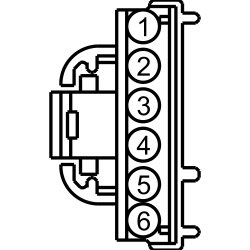 - Is the resistance greater than 10,000 ohms?
| Yes
GO to
N7
.
No
REPAIR the circuit.
|
|
N4 CHECK FOR A VOLTAGE SIGNAL TO THE
|
|
- Disconnect:
C2402.
- Ignition OFF.
- Measure the
voltage
between:
| Positive Lead
| Negative Lead
| | Pin
| Circuit
| Pin
| Circuit
| | C2402-4
| CLS32 (BN)
| —
| Ground
|
 - Is the voltage greater than 11 volts?
| Yes
GO to
N6
.
No
GO to
N5
.
|
|
N5 CHECK THE HAZARD FLASHER LAMP REQUEST INPUT CIRCUIT FOR AN OPEN
|
|
- Disconnect:
C2280B.
- Measure the
resistance
between:
| Positive Lead
| Negative Lead
| | Pin
| Circuit
| Pin
| Circuit
| | C2402-4
| CLS32 (BN)
| C2280B-32
| CLS32 (BN)
|
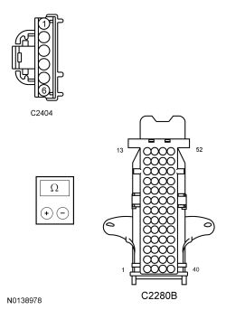 - Is the resistance less than 3 ohms?
| Yes
GO to
N7
.
No
REPAIR the circuit.
|
|
N6 CHECK FOR CORRECT
OPERATION
|
|
- Disconnect and inspect the
connector.
- Repair:
- corrosion (install new connector or terminals – clean module pins)
- damaged or bent pins – install new terminals/pins
- pushed-out pins – install new pins as necessary
- Reconnect the
connector. Make sure it seats correctly.
- Operate the system and determine if the concern is still present.
- Is the concern still present?
| Yes
CHECK On-Line Automotive Service Information System (OASIS) for any applicable TSBs. If a TSB exists for this concern, DISCONTINUE this test and FOLLOW TSB instructions. If no TSBs address this concern, INSTALL a new
. Refer to the appropriate section in Group
415
for the procedure.
No
The system is operating correctly at this time. The concern may have been caused by module connections. ADDRESS the root cause of any connector or pin issues.
|
|
N7 CHECK FOR CORRECT
OPERATION
|
|
- Disconnect and inspect all the
connectors.
- Repair:
- corrosion (install new connector or terminals – clean module pins)
- damaged or bent pins – install new terminals/pins
- pushed-out pins – install new pins as necessary
- Reconnect the
connectors. Make sure they seat and latch correctly.
- Operate the system and determine if the concern is still present.
- Is the concern still present?
| Yes
CHECK On-Line Automotive Service Information System (OASIS) for any applicable TSBs. If a TSB exists for this concern, DISCONTINUE this test and FOLLOW TSB instructions. If no TSBs address this concern, INSTALL a new
. REFER to
Section 419-10
.
No
The system is operating correctly at this time. The concern may have been caused by module connections. ADDRESS the root cause of any connector or pin issues.
|
Pinpoint Test O: One Or More Parking, Rear or License Plate Lamps Is Inoperative
Diagnostic Overview
Diagnostics in this manual assume a certain skill level and knowledge of Ford-specific diagnostic practices. Refer to Diagnostic Methods in
Section 100-00
for information about these practices.
Refer to Wiring Diagrams Cell
92
, Parking, Rear and License Lamps for schematic and connector information.
Normal Operation and Fault Conditions
Refer to System Operation - Parking Lamps in
Parking, Rear and License Plate Lamps
.
Possible Sources
- fuses 30 (15A) (front parking lamps) and 40 (10A) (rear parking lamps)
- fuse 48 (10A) (front parking lamps)
- Wiring, terminals or connectors
- Bulb socket
- Headlamp assembly
- Rear lamp assembly
PINPOINT TEST O: ONE OR MORE PARKING, REAR OR LICENSE PLATE LAMPS IS INOPERATIVE
| Test Step
| Result / Action to Take
|
|---|
|
O1 DETERMINE IF ALL THE PARKING LAMPS ARE INOPERATIVE
|
|
- Ignition OFF.
- Place the headlamp switch in the parking lamps on position.
- Are all the parking lamps inoperative?
| Yes
GO to
O9
.
No
If all the front or all the rear parking lamps are inoperative, VERIFY the
fuse 30 (15A) and
fuse 48 (10A) (front parking lamps) or
fuse 40 (10A) (rear parking lamps) is OK. If OK, GO to
O2
. If not OK, REFER to the Wiring Diagrams manual to identify the possible causes of the circuit short.
For front parking or side marker lamp
, GO to
O3
.
For rear license plate lamp, GO to
O5
.
For rear parking lamp, GO to
O7
.
|
|
O2 BYPASS THE
|
|
NOTE:
If the fuse in the jumper wire fails, refer to the Wiring Diagrams manual to identify the possible causes of the circuit short.
- Place the headlamp switch in the off position.
- Disconnect:
C2280E (inoperative front lamps).
- Disconnect:
C2280D (inoperative rear lamps).
- For inoperative front lamps, connect a
fused jumper wire
between:
| Lead 1
| Lead 2
| | Pin
| Circuit
| Pin
| Circuit
| | C2280E-6
| CBB30 (YE/BU)
| —
| Battery positive
|
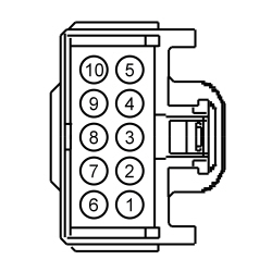 - For inoperative rear lamps, connect a
fused jumper wire
between:
| Lead 1
| Lead 2
| | Pin
| Circuit
| Pin
| Circuit
| | C2280D-18
| CLS30 (VT/WH)
| —
| Battery positive
|
 - Do the front or rear parking lamps illuminate?
| Yes
REMOVE the jumper wire. GO to
O12
.
No
REMOVE the jumper wire. REPAIR
front or rear parking lamp output circuit.
|
|
O3 CHECK INOPERATIVE FRONT PARKING OR SIDE MARKER LAMP VOLTAGE SUPPLY CIRCUIT FOR AN OPEN
|
|
- Place the headlamp switch in the off position.
- Disconnect: Inoperative LH Front Lamp C1115 or RH Front Lamp C1116.
- Disconnect: LH Inoperative Side Marker Lamp, LH Side Marker Lamp C151 (halogen headlamps) or LH Headlamp C1284 (
headlamps).
- Disconnect: RH Inoperative Side Marker Lamp, RH Side Marker Lamp C161 (halogen headlamps) or RH Headlamp C1285 (
headlamps).
- Place the headlamp switch in the parking lamps on position.
- For inoperative front lamps, measure the
voltage
between:
| Positive Lead
| Negative Lead
| | Pin
| Circuit
| Pin
| Circuit
| | LH Front Lamp
| | C1115-2
| CLS30 (VT/WH)
| —
| Ground
| | RH Front Lamp
| | C1116-2
| CLS30 (VT/WH)
| —
| Ground
|
 - For inoperative side marker lamp (halogen headlamps), measure the
voltage
between:
| Positive Lead
| Negative Lead
| | Pin
| Circuit
| Pin
| Circuit
| | LH Side Marker Lamp
| | C151-7
| CLS30 (VT/WH)
| —
| Ground
| | RH Side Marker Lamp
| | C161-7
| CLS30 (VT/WH)
| —
| Ground
|
 - For inoperative side marker lamp (
headlamps), measure the
voltage
between:
| Positive Lead
| Negative Lead
| | Pin
| Circuit
| Pin
| Circuit
| | LH Headlamp
| | C1284-7
| CLS30 (VT/WH)
| —
| Ground
| | RH Headlamp
| | C1285-7
| CLS30 (VT/WH)
| —
| Ground
|
 - Is the voltage greater than 11 volts?
| Yes
GO to
O4
.
No
REPAIR the circuit.
|
|
O4 CHECK THE INOPERATIVE FRONT PARKING OR SIDE MARKER LAMP GROUND CIRCUIT FOR AN OPEN
|
|
- For inoperative front lamp, measure the
voltage
between:
| Positive Lead
| Negative Lead
| | Pin
| Circuit
| Pin
| Circuit
| | LH Front Lamp
| | C1115-2
| CLS30 (VT/WH)
| C1115-1
| GD123 (BK/GY)
| | RH Front Lamp
| | C1116-2
| CLS30 (VT/WH)
| C1116-1
| GD120 (BK/GN)
|
 - For inoperative side marker lamp (halogen headlamps), measure the
voltage
between:
| Positive Lead
| Negative Lead
| | Pin
| Circuit
| Pin
| Circuit
| | LH Side Marker Lamp
| | C151-7
| CLS30 (VT/WH)
| C151-6
| GD123 (BK/GY)
| | RH Side Marker Lamp
| | C161-7
| CLS30 (VT/WH)
| C161-6
| GD120 (BK/GN)
|
 - For inoperative side marker lamp (
headlamps), measure the
voltage
between:
| Positive Lead
| Negative Lead
| | Pin
| Circuit
| Pin
| Circuit
| | LH Headlamp
| | C1284-7
| CLS30 (VT/WH)
| C1284-6
| GD123 (BK/GY)
| | RH Headlamp
| | C1285-7
| CLS30 (VT/WH)
| C1285-6
| GD120 (BK/GN)
|
 - Is the voltage greater than 11 volts?
| Yes
INSTALL a new bulb socket.
No
REPAIR the circuit.
|
|
O5 CHECK INOPERATIVE LICENSE PLATE LAMP VOLTAGE SUPPLY CIRCUIT FOR AN OPEN
|
|
- Place the headlamp switch in the off position.
- Disconnect: Inoperative LH License Plate Lamp C452 or RH License Plate Lamp C462.
- Place the headlamp switch in the parking lamps on position.
- Measure the
voltage
between:
| Positive Lead
| Negative Lead
| | Pin
| Circuit
| Pin
| Circuit
| | LH License Plate Lamp
| | C452-1
| CLS30 (VT/WH)
| —
| Ground
| | RH License Plate Lamp
| | C462-1
| CLS30 (VT/WH)
| —
| Ground
|
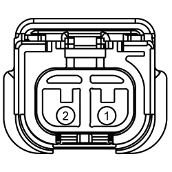 - Is the voltage greater than 11 volts?
| Yes
GO to
O6
.
No
REPAIR the circuit.
|
|
O6 CHECK THE INOPERATIVE LICENSE PLATE LAMP GROUND CIRCUIT FOR AN OPEN
|
|
- Measure the
voltage
between:
| Positive Lead
| Negative Lead
| | Pin
| Circuit
| Pin
| Circuit
| | LH License Plate Lamp
| | C452-1
| CLS30 (VT/WH)
| C452-2
| GD351 (BK/GN)
| | RH License Plate Lamp
| | C462-1
| CLS30 (VT/WH)
| C462-2
| GD351 (BK/GN)
|
 - Is the voltage greater than 11 volts?
| Yes
INSTALL a new bulb socket.
No
REPAIR the circuit.
|
|
O7 CHECK INOPERATIVE REAR PARKING LAMP VOLTAGE SUPPLY CIRCUIT FOR AN OPEN
|
|
- Place the headlamp switch in the off position.
- Disconnect: Inoperative LH Rear Parking Lamp C498 or RH Rear Parking Lamp C499.
- Place the headlamp switch in the parking lamps on position.
- Measure the
voltage
between:
| Positive Lead
| Negative Lead
| | Pin
| Circuit
| Pin
| Circuit
| | LH Rear Parking Lamp
| | C498-2
| CLS30 (VT/WH)
| —
| Ground
| | RH Rear Parking Lamp
| | C499-2
| CLS30 (VT/WH)
| —
| Ground
|
 - Is the voltage greater than 11 volts?
| Yes
GO to
O8
.
No
REPAIR the circuit.
|
|
O8 CHECK THE INOPERATIVE REAR PARKING LAMP GROUND CIRCUIT FOR AN OPEN
|
|
- Measure the
voltage
between:
| Positive Lead
| Negative Lead
| | Pin
| Circuit
| Pin
| Circuit
| | LH Rear Parking Lamp
| | C498-3
| CLS30 (VT/WH)
| C498-1
| GD351 (BK/GN)
| | RH Rear Parking Lamp
| | C499-3
| CLS30 (VT/WH)
| C499-1
| GD349 (BK/GY)
|
 - Is the voltage greater than 11 volts?
| Yes
INSTALL a new bulb socket.
No
REPAIR the circuit.
|
|
O9 CHECK THE
HEADLAMP SWITCH PIDs
|
|
| Yes
GO to
O12
.
No
GO to
O10
.
|
|
O10 CHECK THE HEADLAMP SWITCH
|
|
| Yes
GO to
O11
.
No
INSTALL a new headlamp switch. REFER to
Headlamp Switch
.
|
|
O11 CHECK THE HEADLAMP SWITCH PARKING LAMPS CIRCUIT FOR AN OPEN
|
|
- Disconnect:
C2414A.
- Measure the
resistance
between:
| Positive Lead
| Negative Lead
| | Pin
| Circuit
| Pin
| Circuit
| | C2414A-6
| CLS34 (GY)
| C205-2
| CLS34 (GY)
|
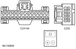 - Is the resistance less than 3 ohms?
| Yes
GO to
O12
.
No
REPAIR the circuit.
|
|
O12 CHECK FOR CORRECT
OPERATION
|
|
- Disconnect and inspect all the
connectors.
- Repair:
- corrosion (install new connector or terminals – clean module pins)
- damaged or bent pins – install new terminals/pins
- pushed-out pins – install new pins as necessary
- Reconnect the
connectors. Make sure they seat and latch correctly.
- Operate the system and determine if the concern is still present.
- Is the concern still present?
| Yes
CHECK On-Line Automotive Service Information System (OASIS) for any applicable TSBs. If a TSB exists for this concern, DISCONTINUE this test and FOLLOW TSB instructions. If no TSBs address this concern, INSTALL a new
. REFER to
Section 419-10
.
No
The system is operating correctly at this time. The concern may have been caused by module connections. ADDRESS the root cause of any connector or pin issues.
|
Pinpoint Test P: The Parking, Rear Or License Plate Lamps Are On Continuously
Diagnostic Overview
Diagnostics in this manual assume a certain skill level and knowledge of Ford-specific diagnostic practices. Refer to Diagnostic Methods in
Section 100-00
for information about these practices.
Refer to Wiring Diagrams Cell
92
, Parking, Rear and License Lamps for schematic and connector information.
Normal Operation and Fault Conditions
Refer to System Operation - Parking Lamps in
Parking, Rear and License Plate Lamps
.
Possible Sources
- Wiring, terminals or connectors
PINPOINT TEST P: THE PARKING, REAR OR LICENSE PLATE LAMPS ARE ON CONTINUOUSLY
| Test Step
| Result / Action to Take
|
|---|
|
P1 CHECK IF THE HEADLAMPS ARE ON
|
|
- Ignition ON.
- Observe the headlamps.
- Are the headlamps illuminated?
| Yes
GO to Pinpoint Test C
.
No
GO to
P2
.
|
|
P2 CHECK THE
REAR PARKING LAMP OUTPUT CIRCUIT FOR A SHORT TO VOLTAGE
|
|
- Ignition OFF.
- Disconnect:
C2280D.
- Ignition ON.
- Do the rear parking lamps continue to illuminate?
| Yes
REPAIR circuit CLS30 (VT/WH).
No
GO to
P3
.
|
|
P3 CHECK THE
FRONT PARKING LAMP OUTPUT CIRCUIT FOR A SHORT TO VOLTAGE
|
|
- Ignition OFF.
- Disconnect:
C2280E.
- Ignition ON.
- Do the front parking lamps continue to illuminate?
| Yes
REPAIR circuit CBB30 (YE/BU).
No
GO to
P4
.
|
|
P4 CHECK FOR CORRECT
OPERATION
|
|
- Disconnect and inspect all the
connectors.
- Repair:
- corrosion (install new connector or terminals – clean module pins)
- damaged or bent pins – install new terminals/pins
- pushed-out pins – install new pins as necessary
- Reconnect the
connectors. Make sure they seat and latch correctly.
- Operate the system and determine if the concern is still present.
- Is the concern still present?
| Yes
CHECK On-Line Automotive Service Information System (OASIS) for any applicable TSBs. If a TSB exists for this concern, DISCONTINUE this test and FOLLOW TSB instructions. If no TSBs address this concern, INSTALL a new
. REFER to
Section 419-10
.
No
The system is operating correctly at this time. The concern may have been caused by module connections. ADDRESS the root cause of any connector or pin issues.
|
Pinpoint Test Q: Both Fog Lamps Are Inoperative
Diagnostic Overview
Diagnostics in this manual assume a certain skill level and knowledge of Ford-specific diagnostic practices. Refer to Diagnostic Methods in
Section 100-00
for information about these practices.
Refer to Wiring Diagrams Cell
86
, Fog Lamps for schematic and connector information.
Normal Operation and Fault Conditions
Refer to System Operation - Fog Lamps in
Fog Lamps
.
Possible Sources
- fuse 47 (15A)
- Wiring, terminals or connectors
- Headlamp switch
PINPOINT TEST Q: BOTH FOG LAMPS ARE INOPERATIVE
Pinpoint Test R: An Individual Fog Lamp Is Inoperative
Diagnostic Overview
Diagnostics in this manual assume a certain skill level and knowledge of Ford-specific diagnostic practices. Refer to Diagnostic Methods in
Section 100-00
for information about these practices.
Refer to Wiring Diagrams Cell
86
, Fog Lamps for schematic and connector information.
Normal Operation and Fault Conditions
Refer to System Operation - Fog Lamps in
Fog Lamps
.
Possible Sources
- Wiring, terminals or connectors
PINPOINT TEST R: AN INDIVIDUAL FOG LAMP IS INOPERATIVE
| Test Step
| Result / Action to Take
|
|---|
|
R1 CHECK FOR VOLTAGE TO THE FOG LAMP
|
|
- Ignition OFF.
- Disconnect: Inoperative LH Fog Lamp C152 or RH Fog Lamp C162.
- Ignition ON.
- Place the headlamp switch in the PARKING LAMPS ON position and engage the fog lamp switch.
- Measure the
voltage
between:
| Positive Lead
| Negative Lead
| | Pin
| Circuit
| Pin
| Circuit
| | LH Fog Lamp
| | C152-1
| CLF12 (BN/YE)
| —
| Ground
| | RH Fog Lamp
| | C162-1
| CLF12 (BN/YE)
| —
| Ground
|
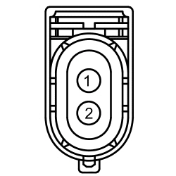 - Is the voltage greater than 11 volts?
| Yes
REPAIR circuit GD123 (BK/GY).
No
REPAIR the circuit.
|
Pinpoint Test S: The Fog Lamps Are On Continuously
Diagnostic Overview
Diagnostics in this manual assume a certain skill level and knowledge of Ford-specific diagnostic practices. Refer to Diagnostic Methods in
Section 100-00
for information about these practices.
Refer to Wiring Diagrams Cell
86
, Fog Lamps for schematic and connector information.
Normal Operation and Fault Conditions
Refer to System Operation - Fog Lamps in
Fog Lamps
.
Possible Sources
- Wiring, terminals or connectors
- Headlamp switch
PINPOINT TEST S: THE FOG LAMPS ARE ON CONTINUOUSLY
| Test Step
| Result / Action to Take
|
|---|
|
S1 CHECK THE FOG LAMP SWITCH PID
|
|
- Ignition ON.
- Enter the following diagnostic mode on the scan tool:
DataLogger.
- Monitor the
fog lamp switch PID (FOG_F_SW) while turning the fog lamp switch on and off.
- Does the PID indicate the fog lamp switch is operating correctly?
| Yes
GO to
S4
.
No
GO to
S2
.
|
|
S2 CHECK THE HEADLAMP SWITCH
|
|
- Ignition OFF.
- Disconnect: Headlamp Switch C205.
- Ignition ON.
- Using a scan tool, monitor the
fog lamp switch PID (FOG_F_SW).
- Does the PID indicate the fog lamp switch is on?
| Yes
GO to
S3
.
No
INSTALL a new headlamp switch. REFER to
Headlamp Switch
.
|
|
S3 CHECK THE FOG LAMP REQUEST INPUT CIRCUIT FOR A SHORT TO GROUND
|
|
- Ignition OFF.
- Disconnect:
C2414A.
- Measure the
resistance
between:
| Positive Lead
| Negative Lead
| | Pin
| Circuit
| Pin
| Circuit
| | C205-5
| CLF21 (GY/VT)
| —
| Ground
|
 - Is the resistance greater than 10,000 ohms?
| Yes
GO to
S6
.
No
REPAIR the circuit.
|
|
S4 CHECK THE
FOG LAMP INDICATOR OUTPUT CIRCUIT FOR A SHORT TO VOLTAGE
|
|
- Ignition OFF.
- Disconnect:
C2280A.
- Ignition ON.
- Do the fog lamps continue to illuminate?
| Yes
GO to
S5
.
No
REPAIR circuit CLF12 (BN/YE) (between the
and the headlamp switch) for a short to voltage.
|
|
S5 CHECK THE
FOG LAMP OUTPUT CIRCUIT FOR A SHORT TO VOLTAGE
|
|
- Ignition OFF.
- Disconnect:
C2280E.
- Ignition ON.
- Do the fog lamps continue to illuminate?
| Yes
REPAIR circuit CLF12 (BN/YE) (between the
and the fog lamps) for a short to voltage.
No
GO to
S7
.
|
|
S6 CHECK FOR CORRECT
OPERATION
|
|
- Disconnect and inspect all the
connectors.
- Repair:
- corrosion (install new connector or terminals – clean module pins)
- damaged or bent pins – install new terminals/pins
- pushed-out pins – install new pins as necessary
- Reconnect the
connectors. Make sure they seat and latch correctly.
- Operate the system and determine if the concern is still present.
- Is the concern still present?
| Yes
CHECK On-Line Automotive Service Information System (OASIS) for any applicable TSBs. If a TSB exists for this concern, DISCONTINUE this test and FOLLOW TSB instructions. If no TSBs address this concern, INSTALL a new
. REFER to
Section 211-05
.
No
The system is operating correctly at this time. The concern may have been caused by module connections. ADDRESS the root cause of any connector or pin issues.
|
|
S7 CHECK FOR CORRECT
OPERATION
|
|
- Disconnect and inspect all the
connectors.
- Repair:
- corrosion (install new connector or terminals – clean module pins)
- damaged or bent pins – install new terminals/pins
- pushed-out pins – install new pins as necessary
- Reconnect the
connectors. Make sure they seat and latch correctly.
- Operate the system and determine if the concern is still present.
- Is the concern still present?
| Yes
CHECK On-Line Automotive Service Information System (OASIS) for any applicable TSBs. If a TSB exists for this concern, DISCONTINUE this test and FOLLOW TSB instructions. If no TSBs address this concern, INSTALL a new
. REFER to
Section 419-10
.
No
The system is operating correctly at this time. The concern may have been caused by module connections. ADDRESS the root cause of any connector or pin issues.
|
Pinpoint Test T: The Fog Lamps On Indicator Is Inoperative
Diagnostic Overview
Diagnostics in this manual assume a certain skill level and knowledge of Ford-specific diagnostic practices. Refer to Diagnostic Methods in
Section 100-00
for information about these practices.
Refer to Wiring Diagrams Cell
86
, Fog Lamps for schematic and connector information.
Normal Operation and Fault Conditions
Refer to System Operation - Fog Lamps in
Fog Lamps
.
Possible Sources
- Wiring, terminals or connectors
- Headlamp switch
PINPOINT TEST T: THE FOG LAMPS ON INDICATOR IS INOPERATIVE
NOTICE:
Use the correct probe adapter(s) when making measurements. Failure to use the correct probe adapter(s) may damage the connector.
| Test Step
| Result / Action to Take
|
|---|
|
T1 CHECK THE HEADLAMP SWITCH
|
|
- Ignition OFF.
- Disconnect: Headlamp Switch C205.
- Ignition ON.
- Enter the following diagnostic mode on the scan tool:
DataLogger.
- Select the
fog lamps active command PID (FOG_LAMPS). Command the fog lamps on.
- NOTE:
Make sure the fog lamps are illuminated when taking a reading.
- Measure the
voltage
between:
| Positive Lead
| Negative Lead
| | Pin
| Circuit
| Pin
| Circuit
| | C205-10
| CLF28 (BN/WH)
| —
| Ground
|
 - Is the voltage greater than 11 volts?
| Yes
INSTALL a new headlamp switch. REFER to
Headlamp Switch
.
No
GO to
T2
.
|
|
T2 CHECK THE
FOG LAMP INDICATOR OUTPUT CIRCUIT FOR AN OPEN
|
|
- Ignition OFF.
- Disconnect:
C2280A.
- Measure the
resistance
between:
| Positive Lead
| Negative Lead
| | Pin
| Circuit
| Pin
| Circuit
| | C205-10
| CLF28 (BN/WH)
| C2280A-2
| CLF28 (BN/WH)
|
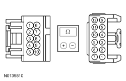 - Is the resistance less than 3 ohms?
| Yes
GO to
T3
.
No
REPAIR the circuit.
|
|
T3 CHECK FOR CORRECT
OPERATION
|
|
- Disconnect and inspect all the
connectors.
- Repair:
- corrosion (install new connector or terminals – clean module pins)
- damaged or bent pins – install new terminals/pins
- pushed-out pins – install new pins as necessary
- Reconnect the
connectors. Make sure they seat and latch correctly.
- Operate the system and determine if the concern is still present.
- Is the concern still present?
| Yes
CHECK On-Line Automotive Service Information System (OASIS) for any applicable TSBs. If a TSB exists for this concern, DISCONTINUE this test and FOLLOW TSB instructions. If no TSBs address this concern, INSTALL a new
. REFER to
Section 419-10
.
No
The system is operating correctly at this time. The concern may have been caused by module connections. ADDRESS the root cause of any connector or pin issues.
|
Pinpoint Test U: All The Reversing Lamps Are Inoperative
Diagnostic Overview
Diagnostics in this manual assume a certain skill level and knowledge of Ford-specific diagnostic practices. Refer to Diagnostic Methods in
Section 100-00
for information about these practices.
Refer to Wiring Diagrams Cell
93
, Reversing Lamps for schematic and connector information.
Normal Operation and Fault Conditions
Refer to System Operation - Reversing Lamps in
Reversing Lamps
.
DTC Fault Trigger Conditions
| DTC
| Description
| Fault Trigger Conditions
|
|---|
| B1277:11
| Reverse Lamp: Circuit Short To Ground
| Sets when the
detects a short to ground from the reversing lamp output circuit.
|
| B1277:15
| Reverse Lamp: Circuit Short To Battery or Open
| Sets when the
detects an open from the reversing lamp output circuit.
|
Possible Sources
- fuse 15 (15A)
- Wiring, terminals or connectors
- Transmission gear input
PINPOINT TEST U: ALL THE REVERSING LAMPS ARE INOPERATIVE
| Test Step
| Result / Action to Take
|
|---|
|
U1 CHECK THE PARKING LAMP OPERATION
|
|
- Ignition OFF.
- Place the headlamp switch in the parking lamps on position.
- Do the parking lamps illuminate?
| Yes
GO to
U2
.
No
GO to
Symptom Chart - : Parking, Rear And License Plate Lamps
.
|
|
U2 CHECK THE
OUTPUT
|
|
- Ignition ON.
- Using a scan tool, view
PIDs.
- Select the
RVRS_LMPS PID. Command the reverse lamps on then off.
- Do the reversing lamps illuminate when commanded on?
| Yes
REFER to
Section 307-01
to diagnose the transmission range input.
No
GO to
U3
.
|
|
U3 BYPASS THE
|
|
NOTE:
If the jumper wire fails, refer to the Wiring Diagrams manual to identify the possible causes of the circuit short.
- Ignition OFF.
- Disconnect:
C2280D.
- Connect a
fused jumper wire
between:
| Lead 1
| Lead 2
| | Pin
| Circuit
| Pin
| Circuit
| | C2280D-13
| CLS28 (BU/WH)
| —
| Battery positive
|
 - Do the reversing lamps illuminate?
| Yes
REMOVE the jumper wire. GO to
U4
.
No
REMOVE the jumper wire. REPAIR the
reverse lamp output circuit for an open.
|
|
U4 CHECK FOR CORRECT
OPERATION
|
|
- Disconnect and inspect all the
connectors.
- Repair:
- corrosion (install new connector or terminals – clean module pins)
- damaged or bent pins – install new terminals/pins
- pushed-out pins – install new pins as necessary
- Reconnect the
connectors. Make sure they seat and latch correctly.
- Operate the system and determine if the concern is still present.
- Is the concern still present?
| Yes
CHECK On-Line Automotive Service Information System (OASIS) for any applicable TSBs. If a TSB exists for this concern, DISCONTINUE this test and FOLLOW TSB instructions. If no TSBs address this concern, INSTALL a new
. REFER to
Section 419-10
.
No
The system is operating correctly at this time. The concern may have been caused by module connections. ADDRESS the root cause of any connector or pin issues.
|
Pinpoint Test V: An Individual Reversing Lamp Is Inoperative
Diagnostic Overview
Diagnostics in this manual assume a certain skill level and knowledge of Ford-specific diagnostic practices. Refer to Diagnostic Methods in
Section 100-00
for information about these practices.
Refer to Wiring Diagrams Cell
93
, Reversing Lamps for schematic and connector information.
Normal Operation and Fault Conditions
Refer to System Operation - Reversing Lamps in
Reversing Lamps
.
Possible Sources
- Wiring, terminals or connectors
- Bulb socket
PINPOINT TEST V: AN INDIVIDUAL REVERSING LAMP IS INOPERATIVE
| Test Step
| Result / Action to Take
|
|---|
|
V1 CHECK THE PARKING LAMP OPERATION
|
|
- Ignition OFF.
- Place the headlamp switch in the parking lamps on position.
- Do the parking lamps illuminate?
| Yes
GO to
V2
.
No
GO to
Symptom Chart - : Parking, Rear And License Plate Lamps
.
|
|
V2 CHECK THE REVERSING LAMP VOLTAGE SUPPLY CIRCUIT FOR AN OPEN
|
|
- Ignition OFF.
- Place the headlamp switch in the OFF position.
- Disconnect: Inoperative LH Rear Lamp C498 or RH Rear Lamp C499.
- Ignition ON.
- Select REVERSE.
- Measure the
voltage
between:
| Positive Lead
| Negative Lead
| | Pin
| Circuit
| Pin
| Circuit
| | LH Reversing Lamp
| | C498-4
| CLS28 (BU/WH)
| —
| Ground
| | RH Reversing Lamp
| | C499-4
| CLS28 (BU/WH)
| —
| Ground
|
 - Is the voltage greater than 11 volts?
| Yes
INSTALL a new bulb socket.
No
REPAIR the circuit.
|
Pinpoint Test W: The Reversing Lamps Are On Continuously
Diagnostic Overview
Diagnostics in this manual assume a certain skill level and knowledge of Ford-specific diagnostic practices. Refer to Diagnostic Methods in
Section 100-00
for information about these practices.
Refer to Wiring Diagrams Cell
93
, Reversing Lamps for schematic and connector information.
Normal Operation and Fault Conditions
Refer to System Operation - Reversing Lamps in
Reversing Lamps
.
DTC Fault Trigger Conditions
| DTC
| Description
| Fault Trigger Conditions
|
|---|
| B1277:15
| Reverse Lamp: Circuit Short To Battery or Open
| Sets when the
detects a short to voltage from the reversing lamp output circuit.
|
Possible Sources
- Wiring, terminals or connectors
- Transmission gear input
PINPOINT TEST W: THE REVERSING LAMPS ARE ON CONTINUOUSLY
| Test Step
| Result / Action to Take
|
|---|
|
W1 CHECK THE
CONTROL OF THE REVERSING LAMPS
|
|
- Ignition ON.
- Using a scan tool, view
PIDs.
- Select the
RVRS_LMPS PID. Command the reverse lamps off.
- Do the reversing lamps turn off?
| Yes
REFER to
Section 307-01
to diagnose the transmission range input.
No
GO to
W2
.
|
|
W2 CHECK THE
OUTPUT
|
|
- Ignition OFF.
- Disconnect:
C2280D.
- Ignition ON.
- Do the reversing lamps continue to illuminate?
| Yes
GO to
W3
.
No
GO to
W4
.
|
|
W3 CHECK THE REVERSING LAMP VOLTAGE SUPPLY CIRCUIT FOR A SHORT TO VOLTAGE
|
|
- Ignition OFF.
- Disconnect: Auto-Dimming Interior Rear View Mirror C911.
- Ignition ON.
- Do the reversing lamps continue to illuminate?
| Yes
REPAIR circuit CLS25 (BU/WH).
No
INSTALL a new auto-dimming interior rear view mirror. REFER to
Section 501-09
.
|
|
W4 CHECK FOR CORRECT
OPERATION
|
|
- Disconnect and inspect all the
connectors.
- Repair:
- corrosion (install new connector or terminals – clean module pins)
- damaged or bent pins – install new terminals/pins
- pushed-out pins – install new pins as necessary
- Reconnect the
connectors. Make sure they seat and latch correctly.
- Operate the system and determine if the concern is still present.
- Is the concern still present?
| Yes
CHECK On-Line Automotive Service Information System (OASIS) for any applicable TSBs. If a TSB exists for this concern, DISCONTINUE this test and FOLLOW TSB instructions. If no TSBs address this concern, INSTALL a new
. REFER to
Section 419-10
.
No
The system is operating correctly at this time. The concern may have been caused by module connections. ADDRESS the root cause of any connector or pin issues.
|
Pinpoint Test X: All the Trailer Lamps Are Inoperative
Diagnostic Overview
Diagnostics in this manual assume a certain skill level and knowledge of Ford-specific diagnostic practices. Refer to Diagnostic Methods in
Section 100-00
for information about these practices.
Refer to Wiring Diagrams Cell
95
, Trailer/Camper Adapter for schematic and connector information.
Normal Operation and Fault Conditions
Refer to System Operation - Trailer Lamps in
Trailer Lamps
.
Possible Sources
- Wiring, terminals or connectors
- Trailer tow connector
- Trailer
PINPOINT TEST X: ALL THE TRAILER LAMPS ARE INOPERATIVE
NOTE:
Before beginning diagnostics, visually inspect the trailer tow connector mounted on the bumper for signs of corrosion or damage. Repair or install a new trailer tow connector as required.
| Test Step
| Result / Action to Take
|
|---|
|
X1 CHECK THE TRAILER TOW RELAYS GROUND CIRCUIT FOR AN OPEN
|
|
- Disconnect: Trailer Tow Parking Lamp Relay.
- Measure the
voltage
between:
| Positive Lead
| Negative Lead
| | Relay Socket
| Circuit
| Relay Socket
| Circuit
| | 3
| SBB84 (GN/RD)
| 2
| GD120 (BK/GN)
|
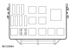 - Is the voltage greater than 11 volts?
| Yes
GO to
X2
.
No
REPAIR the circuit.
|
|
X2 CHECK FOR CONTINUITY TO GROUND THROUGH THE TRAILER TOW CONNECTOR
|
|
- Disconnect: Negative Battery Cable.
- For the 4-pin connector, measure the
resistance
between:
| Positive Lead
| Negative Lead
| | Pin
| Circuit
| Pin
| Circuit
| | C4098-4
| RAT08 (WH)
| —
| Ground
|
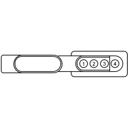 - For the 7-pin connector, measure the
resistance
between:
| Positive Lead
| Negative Lead
| | Pin
| Circuit
| Pin
| Circuit
| | 2
| RAT08 (WH)
| —
| Ground
|
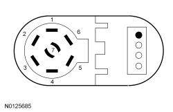 - Is the resistance less than 3 ohms?
| Yes
The vehicle is operating correctly. SEND the trailer to an authorized camper/trailer repair facility.
No
For the 4-pin connector, REPAIR the circuit.
For the 7-pin connector, GO to
X3
.
|
|
X3 CHECK THE TRAILER TOW GROUND CIRCUIT FOR AN OPEN
|
|
- Disconnect: Trailer Tow C4099.
- Measure the
resistance
between:
| Positive Lead
| Negative Lead
| | Pin
| Circuit
| Pin
| Circuit
| | C4099-2
| RAT08 (WH)
| —
| Ground
|
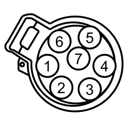 - Is the resistance less than 5 ohms?
| Yes
INSTALL a new trailer tow connector.
No
REPAIR the circuit.
|
Pinpoint Test Y: The Trailer Stop/Turn Lamp Is Inoperative
Diagnostic Overview
Diagnostics in this manual assume a certain skill level and knowledge of Ford-specific diagnostic practices. Refer to Diagnostic Methods in
Section 100-00
for information about these practices.
Refer to Wiring Diagrams Cell
95
, Trailer/Camper Adapter for schematic and connector information.
Normal Operation and Fault Conditions
Refer to System Operation - Trailer Lamps in
Trailer Lamps
.
Possible Sources
- fuse 63 (15A)
- Wiring, terminals or connectors
- Trailer tow connector
- Trailer tow stop/turn relay
- Trailer
PINPOINT TEST Y: THE TRAILER STOP/TURN LAMP IS INOPERATIVE
NOTE:
Before beginning diagnostics, visually inspect the trailer tow connector mounted on the bumper for signs of corrosion or damage. Repair or install a new trailer tow connector as required.
| Test Step
| Result / Action to Take
|
|---|
|
Y1 DETERMINE IF BOTH TRAILER STOP/TURN LAMPS ARE INOPERATIVE
|
|
- Ignition OFF.
- Determine if both trailer stop/turn lamps are inoperative.
- Are both trailer stop/turn lamps inoperative?
| Yes
VERIFY the
fuse 63 (15A) is OK. If OK, REPAIR the trailer stop/turn lamp relay voltage supply circuit for an open. If not OK, REFER to the Wiring Diagrams manual to identify the possible causes of the circuit short.
No
GO to
Y2
.
|
|
Y2 CHECK FOR VOLTAGE THROUGH THE TRAILER TOW CONNECTOR
|
|
- For the 4-pin connector, while applying the brake pedal, measure the
voltage
between:
| Positive Lead
| Negative Lead
| | Pin
| Circuit
| Pin
| Circuit
| | LH Trailer Stop/Turn Lamp
| | C4098-2
| CAT06 (YE)
| —
| Ground
| | RH Trailer Stop/Turn Lamp
| | C4098-1
| CAT09 (GN)
| —
| Ground
|
 - For the 7-pin connector, while applying the brake pedal, measure the
voltage
between:
| Positive Lead
| Negative Lead
| | Pin
| Circuit
| Pin
| Circuit
| | LH Trailer Stop/Turn Lamp
| | 1
| CAT06 (YE)
| —
| Ground
| | RH Trailer Stop/Turn Lamp
| | 4
| CAT09 (GN)
| —
| Ground
|
 - Is the voltage greater than 11 volts?
| Yes
The vehicle is operating correctly. SEND the trailer to an authorized camper/trailer repair facility.
No
For the 4-pin connector, GO to
Y4
.
For the 7-pin connector, GO to
Y3
.
|
|
Y3 CHECK FOR VOLTAGE TO THE TRAILER TOW CONNECTOR
|
|
- Disconnect: Trailer Tow C4099.
- While applying the brake pedal, measure the
voltage
between:
| Positive Lead
| Negative Lead
| | Pin
| Circuit
| Pin
| Circuit
| | LH Trailer Stop/Turn Lamp
| | C4099-1
| CAT06 (YE)
| —
| Ground
| | RH Trailer Stop/Turn Lamp
| | C4099-4
| CAT09 (GN)
| —
| Ground
|
 - Is the voltage greater than 11 volts?
| Yes
INSTALL a new trailer tow connector.
No
GO to
Y4
.
|
|
Y4 CHECK THE TRAILER TOW STOP/TURN RELAY
|
|
- Disconnect: Trailer Tow Left or Right Stop/Turn Relay.
- Substitute a known good relay.
- For the 4-pin connector, while applying the brake pedal, measure the
voltage
between:
| Positive Lead
| Negative Lead
| | Pin
| Circuit
| Pin
| Circuit
| | LH Trailer Stop/Turn Lamp
| | C4098-2
| CAT06 (YE)
| —
| Ground
| | RH Trailer Stop/Turn Lamp
| | C4098-1
| CAT09 (GN)
| —
| Ground
|
 - For the 7-pin connector, while applying the brake pedal, measure the
voltage
between:
| Positive Lead
| Negative Lead
| | Pin
| Circuit
| Pin
| Circuit
| | LH Trailer Stop/Turn Lamp
| | C4099-1
| CAT06 (YE)
| —
| Ground
| | RH Trailer Stop/Turn Lamp
| | C4099-4
| CAT09 (GN)
| —
| Ground
|
 - Is the voltage greater than 11 volts?
| Yes
REMOVE the known good relay. INSTALL a new trailer tow turn relay.
No
REMOVE the known good relay. GO to
Y5
.
|
|
Y5 CHECK FOR VOLTAGE TO THE TRAILER TOW STOP/TURN LAMP RELAY COIL
|
|
- For LH trailer stop/turn lamp, while applying the brake pedal, measure the
voltage
between:
| Positive Lead
| Negative Lead
| | Relay Socket
| Circuit
| Relay Socket
| Circuit
| | 1
| CLS18 (GY/BN)
| —
| Ground
|
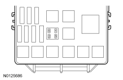 - For RH trailer stop/turn lamp, while applying the brake pedal, measure the
voltage
between:
| Positive Lead
| Negative Lead
| | Relay Socket
| Circuit
| Pin
| Circuit
| | 1
| CLS19 (VT/OG)
| —
| Ground
|
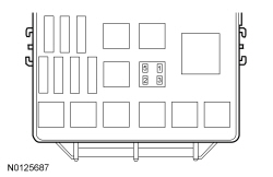 - Is the voltage greater than 11 volts?
| Yes
GO to
Y6
.
No
GO to
Y8
.
|
|
Y6 CHECK THE TRAILER TOW STOP/TURN LAMP RELAY
VOLTAGE SUPPLY CIRCUIT FOR AN OPEN
|
|
- For LH trailer stop/turn lamp, measure the
voltage
between:
| Positive Lead
| Negative Lead
| | Relay Socket
| Circuit
| Pin
| Circuit
| | 3
| SBB63 (WH/RD)
| —
| Ground
|
 - For RH trailer stop/turn lamp, measure the
voltage
between:
| Positive Lead
| Negative Lead
| | Relay Socket
| Circuit
| Pin
| Circuit
| | 3
| SBB63 (WH/RD)
| —
| Ground
|
 - Is the voltage greater than 11 volts?
| Yes
GO to
Y7
.
No
REPAIR the circuit.
|
|
Y7 CHECK THE TRAILER TOW STOP/TURN LAMP RELAY GROUND CIRCUIT FOR AN OPEN
|
|
- For LH trailer stop/turn lamp, measure the
voltage
between:
| Positive Lead
| Negative Lead
| | Relay Socket
| Circuit
| Relay Socket
| Circuit
| | 3
| SBB63 (WH/RD)
| 2
| GD120 (BK/GN)
|
 - For RH trailer stop/turn lamp, measure the
voltage
between:
| Positive Lead
| Negative Lead
| | Relay Socket
| Circuit
| Relay Socket
| Circuit
| | 3
| SBB63 (WH/RD)
| 2
| GD120 (BK/GN)
|
 - Is the voltage greater than 11 volts?
| Yes
REPAIR the trailer tow left stop/turn relay output circuit to the trailer tow connector for an open.
No
REPAIR the trailer tow left stop/turn relay ground circuit for an open.
|
|
Y8 PERFORM THE
SELF-TEST AND RECHECK FOR VOLTAGE TO THE TRAILER TOW STOP/TURN LAMP RELAY COIL
|
|
- For LH trailer stop/turn lamp, measure the
voltage
between:
| Positive Lead
| Negative Lead
| | Relay Socket
| Circuit
| Pin
| Circuit
| | 1
| CLS18 (GY/BN)
| —
| Ground
|
 - For RH trailer stop/turn lamp, measure the
voltage
between:
| Positive Lead
| Negative Lead
| | Relay Socket
| Circuit
| Pin
| Circuit
| | 1
| CLS19 (VT/OG)
| —
| Ground
|
 - Is the voltage greater than 11 volts?
| Yes
INSTALL a new trailer tow turn relay.
No
GO to
Y9
.
|
|
Y9 CHECK THE TRAILER TOW LEFT STOP/TURN LAMP RELAY COIL VOLTAGE SUPPLY CIRCUIT FOR A SHORT TO GROUND
|
|
- Disconnect:
C2280D.
- For LH trailer stop/turn lamp, measure the
resistance
between:
| Positive Lead
| Negative Lead
| | Relay Socket
| Circuit
| Pin
| Circuit
| | 1
| CLS18 (GY/BN)
| —
| Ground
|
 - For RH trailer stop/turn lamp, measure the
resistance
between:
| Positive Lead
| Negative Lead
| | Relay Socket
| Circuit
| Pin
| Circuit
| | 1
| CLS19 (VT/OG)
| —
| Ground
|
 - Is the resistance greater than 10,000 ohms?
| Yes
GO to
Y10
.
No
REPAIR the circuit.
|
|
Y10 CHECK THE TRAILER TOW LEFT STOP/TURN LAMP RELAY COIL VOLTAGE SUPPLY CIRCUIT FOR AN OPEN
|
|
- Measure the
resistance
between:
| Positive Lead
| Negative Lead
| | Relay Socket
| Circuit
| Pin
| Circuit
| | 1
| CLS18 (GY/BN)
| C2280D-12
| CLS18 (GY/BN)
|
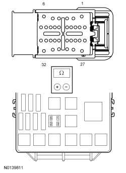 - Measure the
resistance
between:
| Positive Lead
| Negative Lead
| | Relay Socket
| Circuit
| Pin
| Circuit
| | 1
| CLS19 (VT/OG)
| C2280D-15
| CLS19 (VT/OG)
|
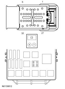 - Is the resistance less than 3 ohms?
| Yes
GO to
Y11
.
No
REPAIR the circuit.
|
|
Y11 CHECK FOR CORRECT
OPERATION
|
|
- Disconnect and inspect all the
connectors.
- Repair:
- corrosion (install new connector or terminals – clean module pins)
- damaged or bent pins – install new terminals/pins
- pushed-out pins – install new pins as necessary
- Reconnect the
connectors. Make sure they seat and latch correctly.
- Operate the system and determine if the concern is still present.
- Is the concern still present?
| Yes
CHECK On-Line Automotive Service Information System (OASIS) for any applicable TSBs. If a TSB exists for this concern, DISCONTINUE this test and FOLLOW TSB instructions. If no TSBs address this concern, INSTALL a new
. REFER to
Section 419-10
.
No
The system is operating correctly at this time. The concern may have been caused by module connections. ADDRESS the root cause of any connector or pin issues.
|
Pinpoint Test Z: The Trailer Parking Lamps Are Inoperative
Diagnostic Overview
Diagnostics in this manual assume a certain skill level and knowledge of Ford-specific diagnostic practices. Refer to Diagnostic Methods in
Section 100-00
for information about these practices.
Refer to Wiring Diagrams Cell
95
, Trailer/Camper Adapter for schematic and connector information.
Normal Operation and Fault Conditions
Refer to System Operation - Trailer Lamps in
Trailer Lamps
.
Possible Sources
- fuse 84 (20A)
- Wiring, terminals or connectors
- Trailer tow connector
- Trailer tow parking lamp relay
- Trailer
PINPOINT TEST Z: THE TRAILER PARKING LAMPS ARE INOPERATIVE
NOTE:
Before beginning diagnostics, visually inspect the trailer tow connector mounted on the bumper for signs of corrosion or damage. Repair or install a new trailer tow connector as required.
| Test Step
| Result / Action to Take
|
|---|
|
Z1 CHECK FOR VOLTAGE THROUGH THE TRAILER TOW CONNECTOR
|
|
- Ignition OFF.
- Place the headlamp switch in the PARKING LAMPS ON position.
- For the 4-pin connector, measure the
voltage
between:
| Positive Lead
| Negative Lead
| | Pin
| Circuit
| Pin
| Circuit
| | C4098-3
| CAT17 (BN)
| —
| Ground
|
 - For the 7-pin connector, measure the
voltage
between:
| Positive Lead
| Negative Lead
| | Pin
| Circuit
| Pin
| Circuit
| | 6
| CAT17 (BN)
| —
| Ground
|
 - Is the voltage greater than 11 volts?
| Yes
The vehicle is operating correctly. SEND the trailer to an authorized camper/trailer repair facility.
No
For the 4-pin connector, GO to
Z3
.
For the 7-pin connector, GO to
Z2
.
|
|
Z2 CHECK FOR VOLTAGE TO THE TRAILER TOW CONNECTOR (7-PIN)
|
|
- Disconnect: Trailer Tow C4099.
- Place the headlamp switch in the PARKING LAMPS ON position.
- Measure the
voltage
between:
| Positive Lead
| Negative Lead
| | Pin
| Circuit
| Pin
| Circuit
| | C4099-6
| CAT17 (BN)
| —
| Ground
|
 - Is the voltage greater than 11 volts?
| Yes
INSTALL a new trailer tow connector.
No
GO to
Z3
.
|
|
Z3 CHECK THE TRAILER TOW PARKING LAMP RELAY
|
|
- Place the headlamp switch in the OFF position.
- Disconnect: Trailer Tow Parking Lamp Relay.
- Substitute a known good relay.
- Place the headlamp switch in the PARKING LAMPS ON position.
- For the 4-pin connector, measure the
voltage
between:
| Positive Lead
| Negative Lead
| | Pin
| Circuit
| Pin
| Circuit
| | C4098-3
| CAT17 (BN)
| —
| Ground
|
 - For the 7-pin connector, measure the
voltage
between:
| Positive Lead
| Negative Lead
| | Pin
| Circuit
| Pin
| Circuit
| | C4099-6
| CAT17 (BN)
| —
| Ground
|
 - Is the voltage greater than 11 volts?
| Yes
REMOVE the known good relay. INSTALL a new trailer tow parking lamp relay.
No
REMOVE the known good relay. GO to
Z4
.
|
|
Z4 CHECK THE TRAILER TOW PARKING LAMP RELAY COIL VOLTAGE SUPPLY CIRCUIT FOR AN OPEN
|
|
- Measure the
voltage
between:
| Positive Lead
| Negative Lead
| | Relay Socket
| Circuit
| Pin
| Circuit
| | 1
| CBB30 (YE/BU)
| —
| Ground
|
 - Is the voltage greater than 11 volts?
| Yes
GO to
Z5
.
No
REPAIR the circuit.
|
|
Z5 CHECK THE TRAILER TOW PARKING LAMP RELAY
VOLTAGE SUPPLY CIRCUIT FOR AN OPEN
|
|
- Measure the
voltage
between:
| Positive Lead
| Negative Lead
| | Relay Socket
| Circuit
| Pin
| Circuit
| | 3
| SBB84 (GN/RD)
| —
| Ground
|
 - Is the voltage greater than 11 volts?
| Yes
GO to
Z6
.
No
VERIFY the
fuse 84 (20A) is OK. If OK, REPAIR the circuit. If not OK, REFER to the Wiring Diagrams manual to identify the possible causes of the circuit short.
|
|
Z6 CHECK THE TRAILER TOW PARKING LAMP RELAY GROUND CIRCUIT FOR AN OPEN
|
|
- Measure the
voltage
between:
| Positive Lead
| Negative Lead
| | Relay Socket
| Circuit
| Relay Socket
| Circuit
| | 3
| SBB84 (GN/RD)
| 2
| GD120 (BK/GN)
|
 - Is the voltage greater than 11 volts?
| Yes
REPAIR the trailer tow parking lamp relay output circuit to the trailer tow connector for an open.
No
REPAIR the trailer tow parking lamp relay ground circuit for an open.
|
Pinpoint Test AA: The Trailer Reversing Lamps Are Inoperative
Diagnostic Overview
Diagnostics in this manual assume a certain skill level and knowledge of Ford-specific diagnostic practices. Refer to Diagnostic Methods in
Section 100-00
for information about these practices.
Refer to Wiring Diagrams Cell
95
, Trailer/Camper Adapter for schematic and connector information.
Normal Operation and Fault Conditions
Refer to System Operation - Trailer Lamps in
Trailer Lamps
.
Possible Sources
- fuse 60 (10A)
- Wiring, terminals or connectors
- Trailer tow connector
- Trailer
PINPOINT TEST AA: THE TRAILER REVERSING LAMPS ARE INOPERATIVE
NOTE:
Before beginning diagnostics, visually inspect the trailer tow connector mounted on the bumper for signs of corrosion or damage. Repair or install a new trailer tow connector as required.
| Test Step
| Result / Action to Take
|
|---|
|
AA1 CHECK FOR VOLTAGE THROUGH THE TRAILER TOW CONNECTOR
|
|
- Apply the parking brake.
- Ignition ON.
- Select REVERSE.
- Measure the
voltage
between:
| Positive Lead
| Negative Lead
| | Pin
| Circuit
| Pin
| Circuit
| | 7
| CAT16 (GY/BN)
| —
| Ground
|
 - Is the voltage greater than 11 volts?
| Yes
The vehicle is operating correctly. SEND the trailer to an authorized camper/trailer repair facility.
No
VERIFY the
fuse 60 (10A) is OK. If OK, GO to
AA2
. If not OK, REFER to the Wiring Diagrams manual to identify the possible causes of the circuit short.
|
|
AA2 CHECK FOR VOLTAGE TO THE TRAILER TOW CONNECTOR (VEHICLE HARNESS)
|
|
- Ignition OFF.
- Disconnect: Trailer Tow C4099.
- Apply the parking brake.
- Ignition ON.
- Select REVERSE.
- Measure the
voltage
between:
| Positive Lead
| Negative Lead
| | Pin
| Circuit
| Pin
| Circuit
| | C4099-7
| CAT16 (GY/BN)
| —
| Ground
|
 - Is the voltage greater than 11 volts?
| Yes
INSTALL a new trailer tow connector.
No
GO to
AA3
.
|
|
AA3 CHECK THE TRAILER TOW REVERSING LAMP RELAY
|
|
- Ignition OFF.
- Disconnect: Trailer Tow Parking Lamp Relay.
- Substitute a known good relay.
- Apply the parking brake.
- Ignition ON.
- Select REVERSE.
- Measure the
voltage
between:
| Positive Lead
| Negative Lead
| | Pin
| Circuit
| Pin
| Circuit
| | C4099-7
| CAT16 (GY/BN)
| —
| Ground
|
 - Is the voltage greater than 11 volts?
| Yes
REMOVE the known good relay. INSTALL a new trailer tow reversing lamp relay.
No
REMOVE the known good relay. GO to
AA4
.
|
|
AA4 CHECK THE TRAILER TOW REVERSING LAMP RELAY COIL VOLTAGE SUPPLY CIRCUIT FOR AN OPEN
|
|
- Measure the
voltage
between:
| Positive Lead
| Negative Lead
| | Relay Socket
| Circuit
| Pin
| Circuit
| | 1
| CLS28 (BU/WH)
| —
| Ground
|
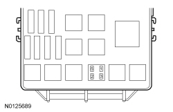 - Is the voltage greater than 11 volts?
| Yes
GO to
AA5
.
No
REPAIR the circuit.
|
|
AA5 CHECK THE TRAILER TOW REVERSING LAMP RELAY VOLTAGE SUPPLY CIRCUIT FOR AN OPEN
|
|
- Select PARK.
- Ignition OFF.
- Measure the
voltage
between:
| Positive Lead
| Negative Lead
| | Relay Socket
| Circuit
| Pin
| Circuit
| | 3
| SBB60 (GN/RD)
| —
| Ground
|
 - Is the voltage greater than 11 volts?
| Yes
GO to
AA6
.
No
REPAIR the circuit.
|
|
AA6 CHECK THE TRAILER TOW REVERSING LAMP RELAY GROUND CIRCUIT FOR AN OPEN
|
|
- Measure the
voltage
between:
| Positive Lead
| Negative Lead
| | Relay Socket
| Circuit
| Relay Socket
| Circuit
| | 3
| SBB60 (GN/RD)
| 2
| GD120 (BK/GN)
|
 - Is the voltage greater than 11 volts?
| Yes
REPAIR the trailer tow reversing lamp relay output circuit to the trailer tow connector for an open.
No
REPAIR the trailer tow reversing lamp relay ground circuit for an open.
|
Pinpoint Test AB: The Trailer Lamps Are On Continuously
Diagnostic Overview
Diagnostics in this manual assume a certain skill level and knowledge of Ford-specific diagnostic practices. Refer to Diagnostic Methods in
Section 100-00
for information about these practices.
Refer to Wiring Diagrams Cell
95
, Trailer/Camper Adapter for schematic and connector information.
Normal Operation and Fault Conditions
Refer to System Operation - Trailer Lamps in
Trailer Lamps
.
Possible Sources
- Wiring, terminals or connectors
- Trailer tow relay
- Trailer
PINPOINT TEST AB: THE TRAILER LAMPS ARE ON CONTINUOUSLY
NOTE:
Before beginning diagnostics, visually inspect the trailer tow connector mounted on the bumper for signs of corrosion or damage. Repair or install a new trailer tow connector as required.
| Test Step
| Result / Action to Take
|
|---|
|
AB1 CHECK FOR VOLTAGE AT THE TRAILER TOW CONNECTOR
|
|
- Ignition ON.
- For the 4-pin connector, measure the
voltage
between:
| Positive Lead
| Negative Lead
| | Pin
| Circuit
| Pin
| Circuit
| | C4098-1
| CAT09 (GN)
| —
| Ground
| | C4098-2
| CAT06 (YE)
| —
| Ground
| | C4098-3
| CAT17 (BN)
| —
| Ground
|
 - For the 7-pin connector, measure the
voltage
between:
| Positive Lead
| Negative Lead
| | Pin
| Circuit
| Pin
| Circuit
| | 1
| CAT06 (YE)
| —
| Ground
| | 4
| CAT09 (GN)
| —
| Ground
| | 6
| CAT17 (BN)
| —
| Ground
| | 7
| CAT16 (GY/BN)
| —
| Ground
|
 - Is any voltage present?
| Yes
GO to
AB2
.
No
The vehicle is operating correctly. SEND the trailer to an authorized camper/trailer repair facility.
|
|
AB2 CHECK THE RELAY OUTPUT CIRCUIT TO THE TRAILER TOW CONNECTOR FOR A SHORT TO VOLTAGE
|
|
- Ignition OFF.
- Disconnect: Suspect Trailer Tow Relay.
- Ignition ON.
- For the 4-pin connector, measure the
voltage
between:
| Positive Lead
| Negative Lead
| | Pin
| Circuit
| Pin
| Circuit
| | C4098-1
| CAT09 (GN)
| —
| Ground
| | C4098-2
| CAT06 (YE)
| —
| Ground
| | C4098-3
| CAT17 (BN)
| —
| Ground
|
 - For the 7-pin connector, measure the
voltage
between:
| Positive Lead
| Negative Lead
| | Pin
| Circuit
| Pin
| Circuit
| | 1
| CAT06 (YE)
| —
| Ground
| | 4
| CAT09 (GN)
| —
| Ground
| | 6
| CAT17 (BN)
| —
| Ground
| | 7
| CAT16 (GY/BN)
| —
| Ground
|
 - Is the trailer tow relay OK?
| Yes
REPAIR the circuit in question.
No
For the trailer tow parking or reversing lamps, INSTALL a new trailer tow relay.
For a trailer tow left or right stop/turn lamp, GO to
AB3
|
|
AB3 CHECK FOR VOLTAGE TO THE TRAILER TOW RELAY COIL
|
|
- For LH trailer stop/turn lamp, measure the
voltage
between:
| Positive Lead
| Negative Lead
| | Relay Socket
| Circuit
| Pin
| Circuit
| | 2
| CLS18 (GY/BN)
| —
| Ground
|
 - For RH trailer stop/turn lamp, measure the
voltage
between:
| Positive Lead
| Negative Lead
| | Relay Socket
| Circuit
| Pin
| Circuit
| | 1
| CLS19 (VT/OG)
| —
| Ground
|
 - Is any voltage present?
| Yes
GO to
AB4
.
No
INSTALL a new trailer tow relay.
|
|
AB4 CHECK FOR VOLTAGE TO THE TRAILER TOW RELAY COIL
|
|
- Ignition OFF.
- Disconnect:
C2280D.
- Ignition ON.
- For LH trailer stop/turn lamp, measure the
voltage
between:
| Positive Lead
| Negative Lead
| | Relay Socket
| Circuit
| Pin
| Circuit
| | 1
| CLS18 (GY/BN)
| —
| Ground
|
 - For RH trailer stop/turn lamp, measure the
voltage
between:
| Positive Lead
| Negative Lead
| | Relay Socket
| Circuit
| Pin
| Circuit
| | 1
| CLS19 (VT/OG)
| —
| Ground
|
 - Is any voltage present?
| Yes
REPAIR the circuit in question.
No
GO to
AB5
.
|
|
AB5 CHECK FOR CORRECT
OPERATION
|
|
- Disconnect and inspect all the
connectors.
- Repair:
- corrosion (install new connector or terminals – clean module pins)
- damaged or bent pins – install new terminals/pins
- pushed-out pins – install new pins as necessary
- Reconnect the
connectors. Make sure they seat and latch correctly.
- Operate the system and determine if the concern is still present.
- Is the concern still present?
| Yes
CHECK On-Line Automotive Service Information System (OASIS) for any applicable TSBs. If a TSB exists for this concern, DISCONTINUE this test and FOLLOW TSB instructions. If no TSBs address this concern, INSTALL a new
. REFER to
Section 419-10
.
No
The system is operating correctly at this time. The concern may have been caused by module connections. ADDRESS the root cause of any connector or pin issues.
|
Pinpoint Test AC: The Trailer Battery Charging Is Inoperative/Does Not Operate Correctly
Diagnostic Overview
Diagnostics in this manual assume a certain skill level and knowledge of Ford-specific diagnostic practices. Refer to Diagnostic Methods in
Section 100-00
for information about these practices.
Refer to Wiring Diagrams Cell
95
, Trailer/Camper Adapter for schematic and connector information.
Normal Operation and Fault Conditions
Refer to System Operation - Trailer Lamps in
Trailer Lamps
.
Possible Sources
- fuse 24 (30A) or 93 (5A)
- Wiring, terminals or connectors
- Trailer tow connector
- Trailer battery charge relay
- Trailer
PINPOINT TEST AC: THE TRAILER BATTERY CHARGING IS INOPERATIVE/DOES NOT OPERATE CORRECTLY
NOTE:
Before beginning diagnostics, visually inspect the trailer tow connector mounted on the bumper for signs of corrosion or damage. Repair or install a new trailer tow connector as required.
| Test Step
| Result / Action to Take
|
|---|
|
AC1 CHECK FOR VOLTAGE THROUGH THE TRAILER TOW CONNECTOR (BATTERY CHARGE INOPERATIVE)
|
|
- Start the engine.
- Measure the
voltage
between:
| Positive Lead
| Negative Lead
| | Pin
| Circuit
| Pin
| Circuit
| | 5
| CAT14 (OG)
| —
| Ground
|
 - Is the voltage greater than 11 volts?
| Yes
GO to
AC2
.
No
VERIFY the
fuse 24 (30A) is OK. If OK, GO to
AC5
. If not OK, REFER to the Wiring Diagrams manual to identify the possible causes of the circuit short.
|
|
AC2 CHECK FOR VOLTAGE AT THE TRAILER TOW CONNECTOR (BATTERY CHARGE ALWAYS ON)
|
|
- Ignition OFF.
- Measure the
voltage
between:
| Positive Lead
| Negative Lead
| | Pin
| Circuit
| Pin
| Circuit
| | 5
| CAT14 (OG)
| —
| Ground
|
 - Is the voltage greater than 11 volts?
| Yes
GO to
AC3
.
No
The vehicle is operating correctly. SEND the trailer to an authorized camper/trailer repair facility.
|
|
AC3 CHECK THE TRAILER TOW BATTERY CHARGE RELAY OUTPUT CIRCUIT FOR A SHORT TO VOLTAGE
|
|
- Disconnect: Trailer Battery Charge Relay.
- Substitute a known good relay.
- Measure the
voltage
between:
| Positive Lead
| Negative Lead
| | Pin
| Circuit
| Pin
| Circuit
| | 5
| CAT14 (OG)
| —
| Ground
|
 - Is any voltage present?
| Yes
REPAIR the circuit.
No
GO to
AC4
.
|
|
AC4 CHECK FOR VOLTAGE TO THE TRAILER BATTERY CHARGE RELAY COIL (ALWAYS ON)
|
|
- Measure the
voltage
between:
| Positive Lead
| Negative Lead
| | Relay Socket
| Circuit
| Pin
| Circuit
| | 1
| CBB93 (GY/BN)
| —
| Ground
|
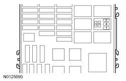 - Is the voltage greater than 11 volts?
| Yes
VERIFY the
fuse 93 (5A) is OK. If OK, REPAIR the circuit. If not OK, REFER to the Wiring Diagrams to identify the possible causes of the circuit short.
No
INSTALL a new trailer tow battery charge relay.
|
|
AC5 CHECK FOR VOLTAGE AT THE TRAILER TOW CONNECTOR (BATTERY CHARGE INOPERATIVE)
|
|
- Ignition OFF.
- Disconnect: Trailer Tow C4099.
- Start the engine.
- Measure the
voltage
between:
| Positive Lead
| Negative Lead
| | Pin
| Circuit
| Pin
| Circuit
| | C4099-5
| CAT14 (OG)
| —
| Ground
|
 - Is the voltage greater than 11 volts?
| Yes
INSTALL a new trailer tow connector.
No
GO to
AC6
.
|
|
AC6 CHECK THE TRAILER TOW BATTERY CHARGE RELAY
|
|
- Ignition OFF.
- Disconnect: Trailer Tow Battery Charge Relay.
- Substitute a known good relay.
- Start the engine.
- Measure the
voltage
between:
| Positive Lead
| Negative Lead
| | Pin
| Circuit
| Pin
| Circuit
| | C4099-5
| CAT14 (OG)
| —
| Ground
|
 - Is the voltage greater than 11 volts?
| Yes
REMOVE the known good relay. INSTALL a new trailer tow battery charge relay.
No
REMOVE the known good relay. GO to
AC7
.
|
|
AC7 CHECK THE TRAILER TOW BATTERY CHARGE RELAY VOLTAGE SUPPLY CIRCUIT FOR AN OPEN
|
|
- Measure the
voltage
between:
| Positive Lead
| Negative Lead
| | Relay Socket
| Circuit
| Pin
| Circuit
| | 3
| SBB24 (VT/RD)
| —
| Ground
|
 - Is the voltage greater than 11 volts?
| Yes
GO to
AC8
.
No
VERIFY the
fuse 24 (30A) is OK. REPAIR the circuit. If not OK, REFER to the Wiring Diagrams manual to identify the possible causes of the circuit short.
|
|
AC8 CHECK THE TRAILER TOW BATTERY CHARGE RELAY COIL VOLTAGE SUPPLY CIRCUIT FOR AN OPEN
|
|
- Ignition ON.
- Measure the
voltage
between:
| Positive Lead
| Negative Lead
| | Relay Socket
| Circuit
| Pin
| Circuit
| | 1
| CBB93 (GY/BN)
| —
| Ground
|
 - Is the voltage greater than 11 volts?
| Yes
GO to
AC9
.
No
VERIFY the
fuse 93 (5A) is OK. REPAIR the circuit. If not OK, REFER to the Wiring Diagrams manual to identify the possible causes of the circuit short.
|
|
AC9 CHECK THE BATTERY CHARGE RELAY COIL GROUND CIRCUIT
|
|
- Ignition OFF.
- Measure the
voltage
between:
| Positive Lead
| Negative Lead
| | Relay Socket
| Circuit
| Relay Socket
| Circuit
| | 3
| SBB24 (VT/RD)
| 2
| CDC65 (BN/YE)
|
 - Is the voltage greater than 11 volts?
| Yes
REPAIR the trailer tow battery charge relay output circuit to the trailer tow connector for an open.
No
GO to
AC10
.
|
|
AC10 CHECK THE BATTERY CHARGE RELAY COIL GROUND CIRCUIT FOR AN OPEN
|
|
- Disconnect:
C2280F.
- Measure the
resistance
between:
| Positive Lead
| Negative Lead
| | Relay Socket
| Circuit
| Pin
| Circuit
| | 2
| CDC66 (BN/YE)
| C2280F-22
| CDC66 (BN/YE)
|
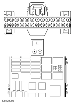 - Is the resistance less than 3 ohms?
| Yes
GO to
AC11
.
No
REPAIR the circuit.
|
|
AC11 CHECK FOR CORRECT
OPERATION
|
|
- Disconnect and inspect all the
connectors.
- Repair:
- corrosion (install new connector or terminals – clean module pins)
- damaged or bent pins – install new terminals/pins
- pushed-out pins – install new pins as necessary
- Reconnect the
connectors. Make sure they seat and latch correctly.
- Operate the system and determine if the concern is still present.
- Is the concern still present?
| Yes
CHECK On-Line Automotive Service Information System (OASIS) for any applicable TSBs. If a TSB exists for this concern, DISCONTINUE this test and FOLLOW TSB instructions. If no TSBs address this concern, INSTALL a new
. REFER to
Section 419-10
.
No
The system is operating correctly at this time. The concern may have been caused by module connections. ADDRESS the root cause of any connector or pin issues.
|
Pinpoint Test AD: The Trailer Electric Brakes Are Inoperative/Do Not Operate Correctly
Diagnostic Overview
Diagnostics in this manual assume a certain skill level and knowledge of Ford-specific diagnostic practices. Refer to Diagnostic Methods in
Section 100-00
for information about these practices.
Refer to Wiring Diagrams Cell
95
, Trailer/Camper Adapter for schematic and connector information.
Normal Operation and Fault Conditions
Refer to System Operation - Trailer Lamps in
Trailer Lamps
.
Possible Sources
- fuse 3 (30A)
- fuse 31 (5A)
- Wiring, terminals or connectors
- Trailer tow connector
- module
- Trailer
PINPOINT TEST AD: THE TRAILER ELECTRIC BRAKES ARE INOPERATIVE/DO NOT OPERATE CORRECTLY
NOTE:
Before beginning diagnostics, visually inspect the trailer tow connector mounted on the bumper for signs of corrosion or damage. Repair or install a new trailer tow connector as required.
| Test Step
| Result / Action to Take
|
|---|
|
AD1 CHECK THE
MODULE FOR A SHORTED OUTPUT
|
|
- Ignition ON.
- Measure the
voltage
between:
| Positive Lead
| Negative Lead
| | Pin
| Circuit
| Pin
| Circuit
| | 3
| CAT19 (BU)
| —
| Ground
|
 - Is any voltage present?
| Yes
GO to
AD2
.
No
GO to
AD3
.
|
|
AD2 CHECK THE
MODULE OUTPUT CIRCUIT FOR A SHORT TO VOLTAGE
|
|
- Ignition OFF.
- Disconnect:
Module C2142.
- Ignition ON.
- Measure the
voltage
between:
| Positive Lead
| Negative Lead
| | Pin
| Circuit
| Pin
| Circuit
| | 3
| CAT19 (BU)
| —
| Ground
|
 - Is any voltage present?
| Yes
REPAIR the circuit.
No
INSTALL a new
module.
|
|
AD3 CHECK THE
MODULE OUTPUT
|
|
- Set the gain on the
module to the maximum setting.
- While applying the brake pedal, measure the
voltage
between:
| Positive Lead
| Negative Lead
| | Pin
| Circuit
| Pin
| Circuit
| | 3
| CAT19 (BU)
| —
| Ground
|
 - Is the voltage greater than 11 volts?
| Yes
The vehicle is operating correctly. SEND the trailer to an authorized camper/trailer repair facility.
No
GO to
AD4
.
|
|
AD4 CHECK FOR VOLTAGE TO THE TRAILER TOW CONNECTOR (VEHICLE HARNESS)
|
|
- Disconnect: Trailer Tow C4099.
- NOTE:
Make sure the gain is set to the maximum setting.
- Measure the
voltage
between:
| Positive Lead
| Negative Lead
| | Pin
| Circuit
| Pin
| Circuit
| | C4099-3
| CAT19 (BU)
| —
| Ground
|
 - Is the voltage greater than 11 volts?
| Yes
INSTALL a new trailer tow connector.
No
GO to
AD5
.
|
|
AD5 CHECK THE
MODULE VOLTAGE SUPPLY CIRCUIT FOR AN OPEN
|
|
- Disconnect:
Module C2142.
- Measure the
voltage
between:
| Positive Lead
| Negative Lead
| | Pin
| Circuit
| Pin
| Circuit
| | C2142-8
| SBB03 (BU/RD)
| —
| Ground
|
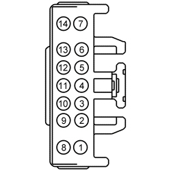 - Is the voltage greater than 11 volts?
| Yes
GO to
AD6
.
No
VERIFY the
fuse 3 (30A) is OK. If OK, REPAIR the circuit. If not OK, REFER to the Wiring Diagrams manual to identify the possible causes of the circuit short.
|
|
AD6 CHECK THE
MODULE GROUND CIRCUIT FOR AN OPEN
|
|
- Measure the
voltage
between:
| Positive Lead
| Negative Lead
| | Pin
| Circuit
| Pin
| Circuit
| | C2142-8
| SBB03 (BU/RD)
| C2142-3
| GD375 (BK/BU)
|
 - Is the voltage greater than 11 volts?
| Yes
GO to
AD7
.
No
REPAIR the circuit.
|
|
AD7 CHECK THE STOPLAMP SWITCH INPUT TO THE
MODULE
|
|
- While applying the brake pedal, measure the
voltage
between:
| Positive Lead
| Negative Lead
| | Pin
| Circuit
| Pin
| Circuit
| | C2142-12
| CBP31 (BU/OG)
| —
| Ground
|
 - Is the voltage greater than 11 volts?
| Yes
GO to
AD8
.
No
VERIFY the
fuse 31 (5A) Is OK. If OK, REPAIR the circuit. If not OK, REFER to the Wiring Diagrams manual to identify the possible causes of the circuit short.
|
|
AD8 CHECK THE
MODULE OUTPUT CIRCUIT FOR A SHORT TO GROUND
|
|
- Disconnect:
C2280B.
- Measure the
resistance
between:
| Positive Lead
| Negative Lead
| | Pin
| Circuit
| Pin
| Circuit
| | C2142-14
| CAT19 (BU)
| —
| Ground
|
 - Is the resistance greater than 10,000 ohms?
| Yes
GO to
AD9
.
No
REPAIR the circuit.
|
|
AD9 CHECK THE
MODULE OUTPUT CIRCUIT FOR AN OPEN
|
|
- Connect a
fused jumper wire
between:
| Lead 1
| Lead 2
| | Pin
| Circuit
| Pin
| Circuit
| | C2142-14
| CAT19 (BU)
| C2142-8
| SBB03 (BU/RD)
|
 - Measure the
voltage
between:
| Positive Lead
| Negative Lead
| | Pin
| Circuit
| Pin
| Circuit
| | C4099-3
| CAT19 (BU)
| —
| Ground
|
 - Is the voltage greater than 11 volts?
| Yes
REMOVE the jumper wire. INSTALL a new
module.
No
REMOVE the jumper wire. REPAIR the circuit.
|


