
NUD105-R025D or equivalent
SECTION 501-12: Instrument Panel and Console
| 2014 Flex Workshop Manual
|
DIAGNOSIS AND TESTING
| Procedure revision date: 05/02/2013
|
 | Flex Probe Kit
NUD105-R025D or equivalent |
Refrigerator Diagnostic Mode
The refrigerator can be switched into a diagnostic mode to read potential on-demand error codes generated by the Compressor Driver Module. When the refrigerator is in diagnostic mode, the FREEZE LED on the refrigerator switch will flash 1-5 times, depending on the error. Perform the following steps in order to access the refrigerator diagnostic mode:
NOTE: Use the Diagnostic Mode Error Code Chart to determine the error.
When the COOL LED is quickly flashing, the FREEZE LED will display the error code by flashing 1-5 times, depending on the error.NOTE: If the refrigerator is in diagnostic mode and the ignition is turned OFF, the refrigerator will restart in COOL mode when the ignition is turned back ON.
To exit diagnostic mode, press the refrigerator switch to the COOL position for approximately 1 second. The COOL LED will stop flashing, but will remain illuminated, and the refrigerator will be in COOL mode.Diagnostic Mode Error Code Chart
| Number of Flashes | Diagnostic Error Code | Diagnostic Error Code Description | Action |
|---|---|---|---|
| 1 | Battery protection cut-out | The voltage supply is below the parameter settings. This code may set when the refrigerator has been active with the engine off. | START the engine and retest. If a concern is still present, GO to Pinpoint Test A . |
| 2 | Fan over-current cut-out | The condenser cooling fan loads the compressor driver module with more than 1 peak amp. | CHECK the console vents, compressor compartment, and condenser for dust collection and/or debris. CHECK the condenser cooling fan for binding and make sure it is free of debris. CLEAN as necessary. INSPECT the condenser cooling fan wiring. TEST for normal operation with the engine running. If a concern is found with the fan or wiring, INSTALL a new refrigerator assembly. REFER to Refrigerator . If a concern was not found with the fan or wiring and error code 2 is still present after cleaning, INSTALL a new compressor driver module. REFER to Compressor Driver Module . |
| 3 | Motor start error | The rotor is blocked or the differential pressure in the refrigeration system is too high (greater than 75.2 psi / 5 bar). This may occur in high ambient temperature situations. This may also result from the refrigerator being turned off and on within a short period of time while a high load/ambient temperature is present. | TURN the refrigerator off. WAIT 15 minutes for the system to release the differential pressure. TEST for normal operation with the engine running. If the concern is still present, INSTALL a new refrigerator assembly. REFER to Refrigerator . |
| 4 | Minimum motor speed error | The compressor motor cannot maintain a minimum speed of 1,850 rpm due to high cooling load or high ambient temperatures. Continuous compressor operation during high ambient temperatures may also cause this concern. | TURN the refrigerator off. WAIT 15 minutes for the refrigerator to cool down. TEST for normal operation with the engine running. If the concern is still present, INSTALL a new refrigerator assembly. REFER to Refrigerator . |
| 5 | Thermal cut-out of electronic unit (compressor driver module) | The compressor driver module has exceeded the maximum temperature limit due to high cooling load or high ambient temperatures. | TURN the refrigerator off. WAIT 15 minutes for the compressor driver module to cool down. CHECK the console vents, compressor compartment, and condenser for dust collection and/or debris. CHECK the condenser cooling fan for binding and make sure it is free of debris. CLEAN as necessary. INSPECT the condenser cooling fan wiring. TEST for normal operation with the engine running. If a concern is found with the fan or wiring, INSTALL a new refrigerator assembly. REFER to Refrigerator . If a concern was not found with the fan or wiring and error code 5 is still present after cleaning, INSTALL a new compressor driver module. REFER to Compressor Driver Module . |
Symptom Chart(s)
Diagnostics in this manual assume a certain skill level and knowledge of Ford-specific diagnostic practices. Refer to Section 100-00 for information about these diagnostic practices.
| Condition | Possible Sources | Action |
|---|---|---|
|
|
|
Pinpoint Tests
Pinpoint Test A: The Refrigerator Is Inoperative/Does Not Operate Correctly
Refer to Wiring Diagrams Cell 105 , Refrigerated Console for schematic and connector information.
Diagnostics in this manual assume a certain skill level and knowledge of Ford-specific diagnostic practices. Refer to Diagnostic Methods in Section 100-00 for information about these practices.
Refer to Refrigerator .
| Signal | Circuit Color | Circuit Function |
|---|---|---|
| C | BU | Acts as the signal ground for the other signal circuits (BN-signal P, GY-signal T, and YE-signal D) |
| P | BN | Supplies reference voltage to the compressor driver module from the refrigerator controller circuit board.
Used to determine the under voltage shut down threshold of the compressor driver module. |
| T | GY | Determines the rotation speed of the compressor.
Controls compressor cycling. |
| D | YE | Transfers the compressor driver module pulse error code(s) to the refrigerator controller circuit board. The refrigerator controller circuit board outputs the error code(s) to the refrigerator switch LED. |
Two circuits between the compressor driver module and compressor supply the 2 phase compressor motor with PWM voltage. The third circuit provides a switched ground signal.
Under normal conditions, voltage must be at least 12.6 volts for the compressor to turn on. The refrigerator controller circuit board is equipped with a battery monitor to prevent the vehicle battery from discharging completely. If the refrigerator is operated at a voltage above 12.6 volts and the battery voltage decreases, the compressor will shut off when the voltage reaches 11.5 volts ± .3 volts. In order for the compressor to switch on again after being switched off by the battery monitor, voltage must be returned to a minimum of 12.9 volts.
NOTICE: Use the correct probe adapter(s) from the Flex Probe Kit when making measurements. Failure to use the correct probe adapter(s) may damage the connector.
| Test Step | Result / Action to Take | ||||||||||||||||||||||||||||||||||||
|---|---|---|---|---|---|---|---|---|---|---|---|---|---|---|---|---|---|---|---|---|---|---|---|---|---|---|---|---|---|---|---|---|---|---|---|---|---|
| A1 CHECK REFRIGERATOR CONTROLLER CIRCUIT BOARD POWER SUPPLY CIRCUIT FOR VOLTAGE | |||||||||||||||||||||||||||||||||||||
NOTE: Most connections on the refrigerator controller circuit board are separate blade terminals. 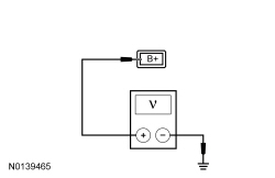 | Yes
GO to A2 . No VERIFY that BCM fuse 37 (10A) is OK. If OK, REPAIR refrigerator controller circuit board power supply circuit (RD B+) or circuit CBP37 (WH). TEST the system for normal operation. If not OK, REFER to the Wiring Diagrams manual to identify the possible causes of the circuit short. REPAIR the circuit. TEST the system for normal operation. | ||||||||||||||||||||||||||||||||||||
| A2 CHECK REFRIGERATOR CONTROLLER CIRCUIT BOARD GROUND CIRCUIT FOR AN OPEN | |||||||||||||||||||||||||||||||||||||
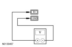 | Yes
GO to A3 . No REPAIR refrigerator controller circuit board ground circuit (BK GND) or circuit GD349 (BK/GY). TEST the system for normal operation. | ||||||||||||||||||||||||||||||||||||
| A3 CHECK THE REFRIGERATOR SWITCH | |||||||||||||||||||||||||||||||||||||
| Yes
GO to A4 . No INSTALL a new refrigerator switch. REFER to Refrigerator Switch . | ||||||||||||||||||||||||||||||||||||
| A4 CHECK REFRIGERATOR CONTROLLER CIRCUIT BOARD TERMINAL FOR VOLTAGE OUTPUT TO COMPRESSOR DRIVER MODULE | |||||||||||||||||||||||||||||||||||||
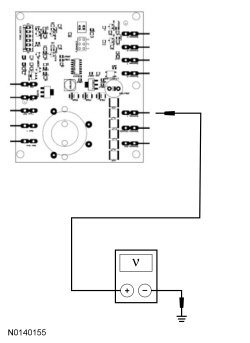 | Yes
GO to A5 . No GO to A11 . | ||||||||||||||||||||||||||||||||||||
| A5 CHECK REFRIGERATOR CONTROLLER CIRCUIT BOARD TERMINAL FOR GROUND SUPPLY FOR THE COMPRESSOR DRIVER MODULE | |||||||||||||||||||||||||||||||||||||
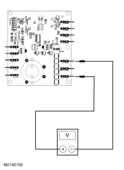 | Yes
GO to A6 . No GO to A11 . | ||||||||||||||||||||||||||||||||||||
| A6 CHECK COMPRESSOR DRIVER MODULE POWER CIRCUIT FOR VOLTAGE | |||||||||||||||||||||||||||||||||||||
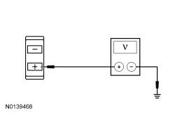 | Yes
GO to A7 . No REPAIR compressor driver module power circuit (RD+). TEST the system for normal operation. | ||||||||||||||||||||||||||||||||||||
| A7 CHECK COMPRESSOR DRIVER MODULE GROUND CIRCUIT FOR AN OPEN | |||||||||||||||||||||||||||||||||||||
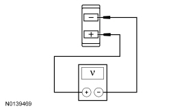 | Yes
GO to A8 . No REPAIR the compressor driver module ground circuit (BK-). TEST the system for normal operation. | ||||||||||||||||||||||||||||||||||||
| A8 CHECK THE CONTROL CIRCUITS FOR A SHORT TO VOLTAGE | |||||||||||||||||||||||||||||||||||||
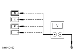 | Yes
REPAIR the circuit in question. TEST the system for normal operation. No GO to A9 . | ||||||||||||||||||||||||||||||||||||
| A9 CHECK THE CONTROL CIRCUITS FOR AN OPEN OR SHORT TO GROUND | |||||||||||||||||||||||||||||||||||||
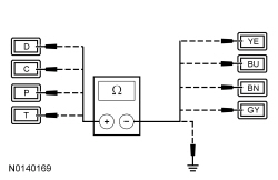 | Yes
GO to A10 . No REPAIR the circuit in question. CLEAR any DTCs present. TEST the system for normal operation. | ||||||||||||||||||||||||||||||||||||
| A10 CHECK FOR CORRECT COMPRESSOR DRIVER MODULE AND COMPRESSOR OPERATION | |||||||||||||||||||||||||||||||||||||
| Yes
INSTALL a new compressor driver module. REFER to Compressor Driver Module . TEST the system for normal operation. If the concern is still present, INSTALL a new refrigerator assembly. REFER to Refrigerator . No The system is operating correctly at this time. The concern may have been caused by a loose or corroded connector. TEST the system for normal operation. | ||||||||||||||||||||||||||||||||||||
| A11 CHECK FOR CORRECT REFRIGERATOR CONTROLLER CIRCUIT BOARD OPERATION | |||||||||||||||||||||||||||||||||||||
| Yes
CHECK OASIS for any applicable TSBs. If a TSB exists for this concern, DISCONTINUE this test and FOLLOW TSB instructions. If no TSBs address this concern, INSTALL a new refrigerator assembly. REFER to Refrigerator . No The system is operating correctly at this time. The concern may have been caused by a loose or corroded connector. ADDRESS the root cause of any connector or pin issues. |
Component Tests
Refrigerator Switch
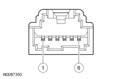
| Connect Self-Powered Test Light Or Ohmmeter To Terminals | Move Refrigerator Switch To This Position | A Good Refrigerator Switch Will Indicate |
|---|---|---|
| 1 and 2 | COOL | Closed |
| 1 and 3 | — | Open |
| 1 and 4 | — | Open |
| 1 and 5 | — | Open |
| 1 and 6 | FREEZE | Closed |
| 2 and 3 | — | Open |
| 2 and 4 | — | Open |
| 2 and 5 | — | Open |
| 2 and 6 | — | Open |
| 3 and 4 | — | Open |
| 3 and 5 | — | Open |
| 3 and 6 | — | Open |
| 4 and 5 | — | Open |
| 4 and 6 | — | Open |
| 5 and 6 | — | Open |