
NUD105-R025D or equivalent

SGT27000 or equivalent 250-300 mA incandescent bulb test lamp
SECTION 501-10: Seating
| 2014 Flex Workshop Manual
|
DIAGNOSIS AND TESTING
| Procedure revision date: 07/31/2013
|
 | Flex Probe Kit
NUD105-R025D or equivalent |
 | Test Light
SGT27000 or equivalent 250-300 mA incandescent bulb test lamp |
Medium Speed Controller Area Network (MS-CAN)
This vehicle utilizes a communication system called a Medium Speed Controller Area Network (MS-CAN). When diagnosing the memory seat or climate controlled seats, use a Vehicle Communication Module (VCM) and Integrated Diagnostic System (IDS) software with appropriate hardware, or equivalent scan tool with the latest software update with the capability of communicating over the MS-CAN bus.
Principles of Operation
Driver and Passenger Power Seats Without Memory
The driver and front passenger power seat uses a 6-way power seat track and 3 electric motors directly controlled by a seat-mounted seat control switch for horizontal (forward/rearward), front height and rear height adjustment. The driver and passenger seats can also be equipped with a power recliner mechanism with power lumbar.
Power Driver Seat With Memory
NOTE: A memory recall can be initiated only if the vehicle is in PARK or NEUTRAL gear and the ignition is not in START. A memory recall in progress is not affected by the ignition being in START or by moving the gearshift lever out of PARK or NEUTRAL.
NOTE: Verify good battery condition before diagnosing the memory seat system. Poor battery condition may interfere with memory seat operation, even if vehicle starting is possible.
The driver power memory seat is controlled by the Driver Seat Module (DSM). The memory seat feature allows the driver to program a personalized seat position that can be recalled using the memory switch or a Remote Keyless Entry (RKE) transmitter. There are 2 memory settings possible. The 2 settings consist of 8 possible directions: the seat can be moved forward or backward and the front and back of the cushion can be moved up and down independently. The backrest of the seat can be moved forward and backward. Adjustable lumbar is not a memory option. The power seat feature operates independent of the ignition position.
The driver seat control switch provides voltage to the DSM when activated. The NEUTRAL position of the driver seat control switch position is a ground state through the seat control switch contacts. A voltage input causes the DSM to power the appropriate motor until the input is removed. Ground is the normal state of the motor circuits through the DSM and is not switched to control the motors. The DSM internally switches the appropriate circuit from ground to voltage for operating the motors.
As the seat is adjusted, the DSM constantly monitors the motor position sensors to record the current seat position. The DSM will remove voltage from the motor upon termination of the seat control switch input or if the DSM does not see movement from the motor by monitoring the position sensor.
The DSM communicates DTCs and other information using the MS-CAN communication bus. It should be noted for diagnostics that because MS-CAN bus communication is more robust and reliable than other methods, it may be possible to have limited module communication with one of the MS-CAN bus circuits disconnected or shorted to ground. Refer to Section 418-00 for information concerning MS-CAN bus communication.
For information on programming memory positions or recalling a stored memory position, refer to Memory Position Programming in this section. For information on RKE transmitter programming, refer to Section 501-14B .
The DSM is located under the driver seat. To install a new DSM , refer to Driver Seat Module (DSM) . Programmable Module Installation (PMI) must be carried out when installing a new DSM . Refer to Section 418-01 .
Driver Seat Module (DSM) Hard Stop/Soft Stop
A hard stop occurs when the seat track or backrest (recline) axes physically reach the end of travel. A soft stop occurs when the seat stops before physically reaching the end of travel. The hard stop is set by seat design and cannot be changed or adjusted. The soft stop is set by the DSM . To prevent unnecessary stress on the seat, the DSM sets 2 soft stops for each moving axis of the seat track and backrest. The DSM uses a preset distance from the hard stop to determine where the soft stop occurs. When an axis reaches the hard stop and the switch is held for approximately one second, it then backs up 180 milliseconds and establishes the soft stop for that axis in that direction.
Easy Exit/Easy Entry
The easy entry/exit feature is a function of the DSM . When the ignition key is removed or for vehicles equipped with passive entry/passive start, when the button is pushed to turn the ignition off, the driver seat moves backward a maximum of 51 mm (2 in) or to the soft stop. The DSM receives a key out command over the MS-CAN communication network and powers the driver seat rearward. The DSM will cancel this operation if a valid input command is received from the driver seat control switch, memory SET switch or exterior mirror control switch.
The DSM will record the current seat position before powering the seat for an easy exit function. This recorded position will be used to return the seat to this position on the easy entry operation. During easy entry operation, the seat is returned to the position previous to the easy exit operation when the key is inserted into the ignition lock cylinder or for vehicles equipped with passive entry/passive start, the ignition button is pressed. Easy entry operation will be cancelled if a valid input command is received by the DSM .
The easy entry/exit feature can be enabled/disabled using a scan tool. When enabled, the feature becomes a user accessible item on the message center allowing the user to turn the feature on and off. Refer to the Owner's Literature or Section 413-01 for information on the message center.
Heated Seats — Front
The driver and passenger heated seat control buttons and indicators are located on the touchscreen interface ( FDIM ). The FDIM is mounted directly to the APIM . The heated seat system functions independently of the vehicle's climate control system. Each time the heated seat button is pressed, the APIM sends the request to the FCIM using the I-CAN . The FCIM sends the message to the IPC using the I-CAN . The IPC sends the request message to the BCM over the HS-CAN . Finally, the BCM sends the request to the HVAC module which decreases one setting (the sequence is high, low, off, high, etc.).
When activated, the HVAC module supplies voltage to the selected seat's heater circuit. Each seat's cushion heater mat and backrest heater mat is connected in a series circuit to the HVAC module and powered by the output circuit for that seat. The HVAC module monitors inputs from a temperature sensor located in each seat's cushion heater mat, and maintains seat temperature by cycling the heater circuits on/off. The heated seat remains ON until the heated seat switch button is pressed to cycle the HVAC module OFF or the ignition is set to OFF.
If a fault is detected by the HVAC module, the module stops supplying voltage to that individual left or right seat that the fault was detected on until the ignition is turned OFF and then ON.
Heated Seats — Rear
Vehicles equipped with rear heated seats are equipped with a single-heated seat module to control both rear heated seats. The heated seat module does not time out. The system will function with the ignition in RUN, whether the engine is running or not. The heated seat module supplies voltage to the heater mats and regulates seat temperature by monitoring a thermostat located in the cushion heater mat.
The heated seat buttons are located in the rear panel of the front floor console. When a heated seat button is pressed, a momentary ground is sent to the heated seat module to turn the heated seat on or off. Pressing the high or low button once turns the heated seat on and pressing the same button a second time turns it off. The heated seat module will send voltage to the separate indicator circuit at the heated seat switch to indicate an on state. The heated seat module will remain on until the heated seat switch is pressed for that high or low mode currently on, sending a second momentary ground signal to the heated seat module or the ignition is set to OFF.
When the heated seat module is on, it provides voltage to the separate indicator circuit at the heated seat button to indicate an on state.
The heated seat module does not report DTCs and does not communicate on the CAN . If a fault is detected, the module will disable the affected seat(s) and indicator(s).
After the fault is corrected, the heated seat module needs to be reset by cycling the ignition OFF and then ON. After the heated seat module has been reset, the module will return to an off state.
Climate Controlled Seat System
NOTICE: Avoid applying voltage directly to a Thermo-Electric Device (TED) for testing its operation. Doing so may cause damage to the TED .
NOTE: When installing a new Dual Climate Controlled Seat Module (DCSM), it is necessary to carry out Programmable Module Installation (PMI). Refer to Section 418-01 .
Both the driver and front passenger climate controlled seats are independently controlled by the DCSM . The climate controlled seat system only operates with the engine running above 350 rpm, however, if using a scan tool to command the DCSM , diagnostic testing can be carried out with the ignition on and engine off. The DCSM does not time out. The DCSM receives voltage from the Battery Junction Box (BJB) on 2 redundant circuits. If one pin does not receive voltage, both seats will remain operational because the voltage supply circuits are internally connected in the DCSM .
If a fault occurs setting a DTC, only the affected seat will be disabled by the module. If the system shuts down due to a DTC fault, cycling the ignition OFF and then ON again will reset the DCSM to function until the DTC resets.
Each driver and front passenger seat cushion and backrest is equipped with a TED and blower motor assembly. Voltage is applied to the TED to heat/cool the seat. Applying voltage polarity to the TED in one direction causes the TED to heat. Applying voltage polarity in the opposite direction causes the TED to cool. Cabin air is drawn through the blower and distributed to each of the TED modules located in the seat cushion and backrest. The TEDs then heat or cool the incoming air depending on the control switch settings. The air is then directed into the foam pad and manifold where it is distributed along the surface of the cushion and backrest of the seat. Once activated, the DCSM maintains the heating/cooling modes until deactivated.
The temperature differences between the individual heated and cooled settings is minimal. For example, it is difficult to distinguish between low cool and medium cool settings. Measuring seat temperature at different settings is possible by monitoring the DCSM PIDs using the scan tool.
When the climate control seat buttons are activated on the touchscreen interface, the APIM sends the climate controlled seat commands to the FCIM using the I-CAN . The FCIM sends the request message to the IPC using the I-CAN . The IPC sends the request message to the BCM over the HS-CAN . Finally the BCM sends the communicates climate controlled seat commands to the DCSM using the MS-CAN . The MS-CAN is connected to the DLC for diagnostic use. No direct connection exists between the DCSM and touchscreen interface for the climate controlled seat buttons. The climate controlled seats can be commanded on or off using the scan tool to verify both module communication on the MS-CAN and operation of the DCSM . This method may be useful for isolating a control switch concern. Refer to Section 418-00 for information concerning CAN .
The climate controlled seats can be commanded using the diagnostic tool to verify both module communication on the MS-CAN bus and operation of the DCSM . This method may be useful for isolating a control switch concern. It should also be noted that because MS-CAN bus communication is more robust and reliable than other methods, it may be possible to have limited module communication with one of the MS-CAN bus circuits disconnected or shorted to ground. Refer to Section 418-00 for information concerning MS-CAN bus communication.
Heating Characteristics
NOTE: The presence of overtemperature faults (DTCs B2729, B2730, B272A and B272B) can be induced by incorrect operation of the climate controlled seat system after an initial HEAT setting has been attained. If a HEAT setting is repeatedly turned OFF and ON in an attempt to increase the seat temperature, an overtemperature condition can result and the DTCs will be set.
Cooling Characteristics
Climate Controlled Seat System Recovery Mode
NOTE: The presence of overtemperature faults (DTCs B2729, B2730, B272A and B272B) can be induced by incorrect operation of the climate controlled seat system after an initial heat setting has been attained. If a heat setting is repeatedly turned OFF and ON in an attempt to increase the seat temperature or repeatedly toggled between heat and cool modes, an overtemperature condition can result and the DTCs will be set.
If the temperature at one of the TEDs rises above 110°C (230°F) in the heat mode or 65°C (149°F) in the cool mode for more than 4 seconds, the DCSM will record an overtemperature DTC, remove voltage from the TEDs and go into recovery mode (blower only) for 30 seconds to cool down the TEDs . The same will occur if a temperature difference of 60°C (108°F) or greater is seen between the backrest and cushion TEDs on either front seat. The DCSM will continue to monitor the TEDs while in recovery mode. If the temperature of the TEDs does not drop to 105°C (221°F) in the heat mode or 60°C (140°F) in the cool mode after 30 seconds, the system will continue to cool the TEDs in recovery mode for up to 5 minutes. If the TEDs cool down at anytime after 30 seconds, but before 5 minutes (checked at 4-second intervals), the system will operate as normal. An overtemperature DTC will still be recorded even if the system recovers and is operating normally. Recovery mode is more likely to occur during extreme cabin temperatures with significant seat back sunload. If the system does not recover within 30 seconds in heat mode or within 5 minutes in cool mode, the DCSM will disable that seat (fault mode) and remain off until the ignition is cycled. Also, if the DCSM detects temperature differential fault twice during the same ignition cycle, it will shutdown. When a fault causes a shutdown, the climate controlled seat indicators will turn off for the affected seat and that seat will not be operational until the next key cycle.
Second Row Power-Fold Seat
For the second row power-fold seat to operate, voltage is supplied by the BCM to the power-fold seat relay, enabling the seats to then be moved by pressing the second row power-fold seat switch.
The power-fold seat relay provides voltage on the coil side from the BCM for 30 minutes when the transmission selector is in PARK, and the liftgate, or liftgate glass, is open. The voltage is disabled 30 minutes after turning the vehicle OFF. If the relay is disabled after 30 minutes, it can be enabled by opening any door, pressing the unlock key on the key fob, pressing any keyless keypad button or turning the ignition key.
The second row power-fold seat motor retracts a cable to release the backrest recliner latches and allows the backrest assist spring to fold the backrest forward onto the seat cushion. The power-fold seat motor continues to retract to release the seat-to floor latches and allows the assist spring and strut dampener to lift and tumble the seat forward to the E-Z entry position for third row seat access. Immediately after the seat is fully released, the power-fold seat motor returns the release cable and latches to a relaxed state, ready for manual latching. To return to a seating position, the seat must be manually latched to the floor and the backrest must be manually latched upright.
Third Row Power Seats
The third row power seat system includes the following components:
The third row power seat relay coil receives voltage from the battery saver relay in the BCM (courtesy lamp circuit) and ground from the chassis. When energized, the relay switch closes and supplies battery voltage from the Battery Junction Box (BJB) to the PFSM . Sufficient battery voltage is required for PFSM operation. If battery voltage drops below 8 volts, a started seat movement stops.
When the gear selector lever is in the PARK position and the liftgate is open, the BCM supplies voltage to the PFSM enable circuit for 30 minutes. With the ignition OFF, the BCM disables the battery saver relay after 10 minutes. The system can be re-enabled by opening any door, pressing the unlock button on the RKE transmitter or turning the ignition ON. A short to voltage on the PFSM enable circuit can result in the third row power seat being operational any time the battery saver relay is energized, regardless of gear selector lever or tailgate position.
The seat control switch contains the seat selector switch button and seat position switch buttons. The PFSM receives a voltage signal from the seat selector switch for 3 modes:
The PFSM receives voltage signals from the seat position switches for 4 possible seat positions:
The power-stow seat motor assemblies rotate the LH or RH seat cushion assemblies together or separately (based on seat[s] selected) and are located at the outboard seat positions. The motor assemblies contain Hall-effect sensors that indicate seat position to the PFSM . The power-stow seat motor assemblies are part of the third row seat pivot tube assembly and are not serviceable separately.
The power-fold motor assemblies rotate the LH or RH seat backrests and are located at the backrest lower outboard positions. The motor assemblies contain Hall-effect sensors that indicate seat backrest position to the PFSM . The LH and RH power-fold motor assemblies are serviceable individually.
The LH and RH latch motors receive voltage from the PFSM . The motors share a common ground supplied by the PFSM . The seat latch motors energize and release the seat latch mechanism(s) when STOW and TAILGATE positions are selected.
The latch switches are normally open and receive approximately 12 volts from the PFSM . The LH and RH latch switches share a common return circuit in series to the PFSM . The PFSM monitors the latch switch circuits to determine if the seat latches are open or closed. The latch switch is mounted to seat latch mechanism and is not serviceable. A new power seat latch must be installed.
When STOW, FOLD or TAILGATE is selected the backrest folds forward enough to release the spring loaded headrest. If the head restraint is not folded prior to achieving FOLD, STOW or TAILGATE positions, the head restraint becomes an obstruction and prevents the seat from completing the seat movement. When an obstruction is detected during any seat movement, the seat stops, reverses movement a few inches and then stops again until the obstruction is removed. When the obstruction has been removed the seat control switch must be pressed again to reset the request. The seat moves to the home position (seat folded and latched to the floor) and then continues to the requested seat position.
On the first press of the seat control switch after the seat is repaired and a new system component has been installed, the PFSM moves the seat to the home position (seat folded and latched to the floor) before continuing to move to the selected seat position. This allows the PFSM to relearn the position of the affected motors.
Inspection and Verification
Visual Inspection Chart
| Mechanical | Electrical |
|---|---|
|
|
NOTE: Make sure to use the latest scan tool software release.
If the concern is with the memory seat and the cause is not visually evident, connect the scan tool to the Data Link Connector (DLC).NOTE: The Vehicle Communication Module (VCM) LED prove out confirms power and ground from the DLC are provided to the VCM .
If the scan tool does not communicate with the VCM :DTC Charts
Body Control Module (BCM) DTC Chart
| DTC | Description | Retrieved | Action |
|---|---|---|---|
| B1317:11 | Third Row Power Fold Seat Output: Circuit Short To Ground | On-Demand | GO to Pinpoint Test AF . |
| B1317:15 | Third Row Power Fold Seat Output: Circuit Short To Battery or Open | On-Demand and Continuous | If the third row power-fold seats do not operate,
GO to Pinpoint Test AF
.
If the third row power-fold seats do operate, REPAIR the Power-Fold Seat Module (PFSM) enable circuit CPS48 (BU) for a short to voltage. CLEAR the DTCs. REPEAT the self-test. TEST the system for normal operation. |
| All Other DTCs | — | — | REFER to Section 419-10 . |
Dual Climate Controlled Seat Module (DCSM) DTC Chart
| DTC | Description | Retrieved | Action |
|---|---|---|---|
| B103B | Thermoelectric Driver Overcurrent Low | On-Demand and Continuous | GO to Pinpoint Test BE . |
| B103C | Thermoelectric Driver Open Load | On-Demand and Continuous | GO to Pinpoint Test BF . |
| B103D | Blower Driver Overtemperature | On-Demand and Continuous | GO to Pinpoint Test BG . |
| B1111 | Driver Thermo Electric Device Control Overtemperature Fault | On-Demand and Continuous | GO to Pinpoint Test BE . |
| B1113 | Passenger Thermo Electric Device Control Overtemperature Fault | On-Demand and Continuous | GO to Pinpoint Test BH . |
| B111B | Passenger Thermoelectric Driver Overcurrent Low | On-Demand and Continuous | GO to Pinpoint Test BH . |
| B111C | Passenger Thermoelectric Driver Open Load | On-Demand and Continuous | GO to Pinpoint Test BI . |
| B111D | Passenger Blower Driver Overtemperature | On-Demand and Continuous | GO to Pinpoint Test BJ . |
| B1342 | ECU is Faulted | On-Demand and Continuous | INSTALL a new Dual Climate Controlled Seat Module (DCSM). REFER to Dual Climate Controlled Seat Module (DCSM) in this section. |
| B19A1 | Passenger Seat Cushion Blower Speed Short to Battery | On-Demand and Continuous | GO to Pinpoint Test BK . |
| B19A2 | Passenger Seat Back Blower Speed Short to Battery | On-Demand and Continuous | GO to Pinpoint Test BL . |
| B19A3 | Driver Seat Cushion Blower Speed Short to Battery | On-Demand and Continuous | GO to Pinpoint Test BM . |
| B19A4 | Driver Seat Back Blower Speed Short to Battery | On-Demand and Continuous | GO to Pinpoint Test AQ . |
| B19A5 | Passenger Seat Cushion Blower Speed Short to Ground | On-Demand and Continuous | GO to Pinpoint Test AR . |
| B19A6 | Passenger Seat Back Blower Speed Short to Ground | On-Demand and Continuous | GO to Pinpoint Test AS . |
| B19A7 | Driver Seat Cushion Blower Speed Short to Ground | On-Demand and Continuous | GO to Pinpoint Test AT . |
| B19A8 | Driver Seat Back Blower Speed Short to Ground | On-Demand and Continuous | GO to Pinpoint Test AU . |
| B2477 | Module Configuration Failure | On-Demand and Continuous | NOTE: This DTC indicates PMI has not been done to a newly installed module or configuration data has been lost. CARRY OUT Programmable Module Installation (PMI) on the DCSM . REFER to Section 418-01 . REPEAT the self-test. If PMI is successful, the DTC will not be present. |
| B2486 | Climate Control Seat Module Voltage Out of Range | On-Demand and Continuous | GO to Pinpoint Test AV . |
| B2729 | Cushion Over-Temp Detected | On-Demand and Continuous | GO to Pinpoint Test AW . |
| B272A | Passenger Cushion Over-Temp Detected | On-Demand and Continuous | GO to Pinpoint Test AX . |
| B272B | Passenger Back Over-Temp Detected | On-Demand and Continuous | GO to Pinpoint Test AY . |
| B272C | Driver Differential Temperature Fault | On-Demand and Continuous | GO to Pinpoint Test AZ . |
| B272D | Passenger Differential Temperature Fault | On-Demand and Continuous | GO to Pinpoint Test BA . |
| B272E | Driver Ignition Run/Blower Circuit Short to Ground | On-Demand and Continuous | GO to Pinpoint Test BB . |
| B272F | Passenger Ignition Run/Blower Circuit Short to Ground | On-Demand and Continuous | GO to Pinpoint Test BC . |
| B2730 | Back Over-Temp Detected | On-Demand and Continuous | GO to Pinpoint Test BD . |
| U2050 | No Application Present | Continuous | INSTALL a new DCSM . REFER to Dual Climate Controlled Seat Module (DCSM) in this section. REPEAT the self-test. |
Driver Door Module (DDM) DTC Chart
| DTC | Description | Action |
|---|---|---|
| B1534 | Memory 1 Switch Circuit Short to Ground | GO to Pinpoint Test K . |
| B1538 | Memory 2 Switch Circuit Short to Ground | GO to Pinpoint Test K . |
| All other DTCs | — | REFER to Section 501-14A or Section 501-14B . |
Driver Seat Module (DSM) DTC Chart
| DTC | Description | Retrieved | Action |
|---|---|---|---|
| B106E | Solid State Driver Disabled Due To Short Circuit | Driver Seat Module (DSM) | GO to Pinpoint Test AM . |
| B106F | Module Disabled Due To External Fault | DSM | GO to Pinpoint Test AM . |
| B112B | Mirror Power Fold Switch Input Short to Battery | DSM | REFER to Section 501-09 . |
| B1317 | Battery Voltage High | Continuous | GO to Pinpoint Test AD . |
| B1318 | Battery Voltage Low | Continuous | GO to Pinpoint Test AN . |
| B1342 | ECU is Faulted | On-Demand and Continuous | INSTALL a new Driver Seat Module (DSM). REFER to Driver Seat Module (DSM) in this section. CLEAR the DTCs. REPEAT the self-test. |
| B1663 | Seat Driver Front Up/Down Motor Stalled | On-Demand | If the motor does not operate, GO to Pinpoint Test J . If motor operates, GO to Pinpoint Test K . |
| B1664 | Seat Driver Rear Up/Down Motor Stalled | On-Demand | If the motor does not operate, GO to Pinpoint Test J . If motor operates, GO to Pinpoint Test K . |
| B1665 | Seat Driver Forward/Backward Motor Stalled | On-Demand | If the motor does not operate, GO to Pinpoint Test J . If motor operates, GO to Pinpoint Test K . |
| B1666 | Seat Driver Recline Motor Stalled | On-Demand | If the motor does not operate, GO to Pinpoint Test J . If motor operates, GO to Pinpoint Test K . |
| B1669 | Mirror Passenger Up/Down Motor Stalled | — | REFER to Section 501-09 . |
| B1670 | Mirror Passenger Right/Left Motor Stalled | — | REFER to Section 501-09 . |
| B1703 | Seat Driver Recline Forward Switch Circuit Short To Battery | On-Demand and Continuous | GO to Pinpoint Test J . |
| B1707 | Seat Driver Recline Rearward Switch Circuit Short To Battery | On-Demand and Continuous | GO to Pinpoint Test J . |
| B1711 | Seat Driver Front Up Switch Circuit Short To Battery | On-Demand and Continuous | GO to Pinpoint Test J . |
| B1715 | Seat Driver Front Down Switch Circuit Short To Battery | On-Demand and Continuous | GO to Pinpoint Test J . |
| B1719 | Seat Driver Forward Switch Circuit Short To Battery | On-Demand and Continuous | GO to Pinpoint Test J . |
| B1723 | Seat Driver Rearward Switch Circuit Short To Battery | On-Demand and Continuous | GO to Pinpoint Test J . |
| B1727 | Seat Driver Rear Up Switch Circuit Short To Battery | On-Demand and Continuous | GO to Pinpoint Test J . |
| B1731 | Seat Driver Rear Down Switch Circuit Short To Battery | On-Demand and Continuous | GO to Pinpoint Test J . |
| B1952 | Seat Rear Up/Down Position Feedback Circuit Short To Battery | On-Demand and Continuous | GO to Pinpoint Test K . |
| B1953 | Seat Rear Up/Down Position Feedback Circuit Short To Ground | On-Demand and Continuous | GO to Pinpoint Test K . |
| B1956 | Seat Front Up/Down Position Feedback Circuit Short To Battery | On-Demand and Continuous | GO to Pinpoint Test K . |
| B1957 | Seat Front Up/Down Position Feedback Circuit Short To Ground | On-Demand and Continuous | GO to Pinpoint Test K . |
| B1960 | Seat Recline Forward/Backward Position Feedback Circuit Short To Battery | On-Demand and Continuous | GO to Pinpoint Test K . |
| B1961 | Seat Recline Forward/Backward Position Feedback Circuit Short To Ground | On-Demand and Continuous | GO to Pinpoint Test K . |
| B1964 | Seat Horizontal Forward/Rearward Position Feedback Circuit Short To Battery | On-Demand and Continuous | GO to Pinpoint Test K . |
| B1965 | Seat Horizontal Forward/Rearward Position Feedback Circuit Short To Ground | On-Demand and Continuous | GO to Pinpoint Test K . |
| B2224 | Mirror Passenger Drive Circuit Failure | — | REFER to Section 501-09 . |
| B2312 | Mirror Passenger Horizontal Feedback Potentiometer Circuit Failure | — | REFER to Section 501-09 . |
| B2314 | Mirror Passenger Horizontal Feedback Potentiometer Circuit Short to Battery | — | REFER to Section 501-09 . |
| B2316 | Mirror Passenger Vertical Feedback Potentiometer Circuit Failure | — | REFER to Section 501-09 . |
| B2318 | Mirror Passenger Vertical Feedback Potentiometer Circuit Short to Battery | — | REFER to Section 501-09 . |
| B2477 | Module Configuration Failure | Continuous | REFER to Section 418-01 . |
| U0140 | Lost Communication With Body Control Module (GEM) | Continuous | GO to Pinpoint Test AO . |
| U2050 | No Application Present | Continuous | INSTALL a new Driver Seat Module (DSM). REFER to Driver Seat Module (DSM) in this section. CLEAR the DTCs. REPEAT the self-test. |
HVAC Module DTC Chart
| DTC | Description | Action to Take |
|---|---|---|
| B1034:11 | Left Front Seat Heater Element: Circuit Short to Ground | GO to Pinpoint Test N . |
| B1034:13 | Left Front Seat Heater Element: Circuit Open | GO to Pinpoint Test N . |
| B1036:11 | Right Front Seat Heater Element: Circuit Short to Ground | GO to Pinpoint Test O . |
| B1036:13 | Right Front Seat Heater Element: Circuit Open | GO to Pinpoint Test O . |
| B1038:11 | Left Front Seat Heater Sensor: Circuit Short to Ground | GO to Pinpoint Test N . |
| B1038:12 | Left Front Seat Heater Sensor: Circuit Short to Battery | GO to Pinpoint Test N . |
| B103A:11 | Right Front Seat Heater Sensor: Circuit Short to Ground | GO to Pinpoint Test O . |
| B103A:12 | Right Front Seat Heater Sensor: Circuit Short to Battery | GO to Pinpoint Test O . |
| All other DTCs | — | REFER to Section 412-00 . |
Symptom Chart
| Condition | Possible Sources | Action |
|---|---|---|
|
|
|
|
| |
|
| |
|
| |
|
| |
|
|
|
|
| |
|
| |
|
| |
|
| |
|
| |
|
| |
|
| |
|
|
|
|
| |
|
|
|
|
| |
|
| |
|
| |
|
|
|
|
|
|
|
|
|
|
| |
|
| |
|
| |
|
| |
|
| |
|
| |
|
| |
|
| |
|
| |
|
| |
|
| |
|
| |
|
| |
|
| |
|
|
|
Pinpoint Tests
NOTICE: Use the correct probe adapter(s) when taking measurements. Failure to use the correct probe adapter(s) may damage the connector.
NOTE: Most faults are due to connector and/or wiring concerns. Carry out a thorough inspection and verification before proceeding with the pinpoint test.
Refer to Inspection and Verification, the Driver Seat Module (DSM) DTC Chart, HVAC Module DTC Chart, BCM DTC Chart and the Symptom Chart for direction to the appropriate pinpoint test.
Pinpoint Test A: The Power Seat is Inoperative — Driver, With Power Recliner
Refer to Wiring Diagrams Cell 120 , Power Seats for schematic and connector information.
The driver seat control switch is supplied battery voltage and ground. When pressed, the seat control switch supplies voltage and ground to a power seat track motor or power recliner motor to move the seat or backrest to the desired position. There are 3 power seat track motors that combine to move the seat cushion horizontally (forward/rearward) and vertically (front up/down and rear up/down). There is an additional motor in the power recliner mechanism to move the seat backrest forward and rearward. If a new motor needs to be installed, it is necessary to install an entire power seat track or power recliner mechanism.
NOTE: The air bag warning indicator illuminates when the correct Restraints Control Module (RCM) fuse is removed and the ignition switch is on.
NOTE: The Supplemental Restraint System (SRS) must be fully operational and free of faults before releasing the vehicle to the customer.
| Test Step | Result / Action to Take |
|---|---|
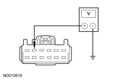
| A1 CHECK THE DRIVER SEAT CONTROL SWITCH FOR VOLTAGE | |
 | Yes
GO to A2 . No VERIFY Battery Junction Box (BJB) fuse 23 (30A) is OK. If OK, REPAIR the circuit. If not OK, REFER to the Wiring Diagrams manual to identify possible causes of the circuit short. TEST the system for normal operation. DISCONNECT the battery ground cable. CONNECT driver seat side air bag C367 and driver seat safety belt buckle C3065. REPOWER the SRS . REFER to Section 501-20B . |
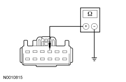
| A2 CHECK DRIVER SEAT CONTROL SWITCH GROUND CIRCUIT FOR AN OPEN | |
 | Yes
INSTALL a new driver seat control switch. REFER to Seat Control Switch — Front in this section. TEST the system for normal operation. DISCONNECT the battery ground cable. CONNECT driver seat side air bag C367 and driver seat safety belt buckle C3065. REPOWER the SRS . REFER to Section 501-20B . No REPAIR the circuit. TEST the system for normal operation. DISCONNECT the battery ground cable. CONNECT driver seat side air bag C367 and driver seat safety belt buckle C3065. REPOWER the SRS . REFER to Section 501-20B . |
Pinpoint Test B: The Power Seat is Inoperative — Driver, Without Power Recliner
Refer to Wiring Diagrams Cell 120 , Power Seats for schematic and connector information.
The driver seat control switch is supplied battery voltage and ground. When pressed, the seat control switch supplies that voltage and ground to a power seat track motor to move the seat to the desired position. There are 3 power seat track motors that combine to move the seat cushion horizontally (forward/rearward) and vertically (front up/down and rear up/down). If a new motor needs to be installed, it is necessary to install an entire power seat track.
NOTE: The air bag warning indicator illuminates when the correct Restraints Control Module (RCM) fuse is removed and the ignition switch is on.
NOTE: The Supplemental Restraint System (SRS) must be fully operational and free of faults before releasing the vehicle to the customer.
| Test Step | Result / Action to Take |
|---|---|
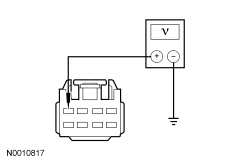
| B1 CHECK THE DRIVER SEAT CONTROL SWITCH FOR VOLTAGE | |
 | Yes
GO to B2 . No VERIFY Battery Junction Box (BJB) fuse 23 (30A) is OK. If OK, REPAIR the circuit. If not OK, REFER to the Wiring Diagrams manual to identify possible causes of the circuit short. TEST the system for normal operation. DISCONNECT the battery ground cable. CONNECT driver seat side air bag C367 and driver seat safety belt buckle C3065. REPOWER the SRS . REFER to Section 501-20B . |
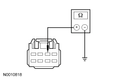
| B2 CHECK DRIVER SEAT CONTROL SWITCH GROUND CIRCUIT FOR AN OPEN | |
 | Yes
INSTALL a new driver seat control switch. REFER to Seat Control Switch — Front in this section. TEST the system for normal operation. DISCONNECT the battery ground cable. CONNECT driver seat side air bag C367 and driver seat safety belt buckle C3065. REPOWER the SRS . REFER to Section 501-20B . No REPAIR the circuit. TEST the system for normal operation. DISCONNECT the battery ground cable. CONNECT driver seat side air bag C367 and driver seat safety belt buckle C3065. REPOWER the SRS . REFER to Section 501-20B . |
Pinpoint Test C: The Power Seat is Inoperative — Passenger, Without Power Recliner
Refer to Wiring Diagrams Cell 120 , Power Seats for schematic and connector information.
The passenger seat control switch is supplied battery voltage and ground. When pressed, the seat control switch supplies voltage and ground to the appropriate seat track motor to move the seat to the desired position. There are 3 seat track motors that combine to move the seat cushion horizontally (forward/rearward) and vertically (front up/down and rear up/down).
NOTE: The air bag warning indicator illuminates when the correct Restraints Control Module (RCM) fuse is removed and the ignition switch is on.
NOTE: The Supplemental Restraint System (SRS) must be fully operational and free of faults before releasing the vehicle to the customer.
| Test Step | Result / Action to Take |
|---|---|
| C1 CHECK THE PASSENGER SEAT CONTROL SWITCH FOR VOLTAGE | |
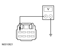 | Yes
GO to C2 . No VERIFY Battery Junction Box (BJB) fuse 42 (30A) is OK. If OK, REPAIR the circuit. If not OK, REFER to the Wiring Diagrams manual to identify possible causes of the circuit short. TEST the system for normal operation. DISCONNECT the battery ground cable. CONNECT passenger seat side air bag C337 and passenger safety belt buckle C3066. REPOWER the SRS . REFER to Section 501-20B . |
| C2 CHECK THE PASSENGER SEAT CONTROL SWITCH GROUND CIRCUIT FOR AN OPEN | |
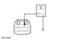 | Yes
INSTALL a new passenger seat control switch. REFER to Seat Control Switch — Front in this section. TEST the system for normal operation. DISCONNECT the battery ground cable. CONNECT passenger seat side air bag C337 and passenger safety belt buckle C3066. REPOWER the SRS . REFER to Section 501-20B . No REPAIR the circuit. TEST the system for normal operation. DISCONNECT the battery ground cable. CONNECT passenger seat side air bag C337 and passenger safety belt buckle C3066. REPOWER the SRS . REFER to Section 501-20B . |
Pinpoint Test D: The Power Seat Does Not Move Horizontally/Vertically/Recline — Driver, With Power Recliner
Refer to Wiring Diagrams Cell 120 , Power Seats for schematic and connector information.
The driver seat control switch is supplied battery voltage and ground. When pressed, the seat control switch supplies voltage and ground to the appropriate power seat track motor or power recliner motor to move the seat or backrest. There are 3 power seat track motors that combine to move the seat cushion horizontally (forward/rearward) and vertically (front up/down and rear up/down). There is an additional motor in the power recliner mechanism to pivot the seat backrest forward and rearward.
NOTE: The air bag warning indicator illuminates when the correct Restraints Control Module (RCM) fuse is removed and the ignition switch is on.
NOTE: The Supplemental Restraint System (SRS) must be fully operational and free of faults before releasing the vehicle to the customer.
| Test Step | Result / Action to Take |
|---|---|
| D1 CHECK HORIZONTAL MOTOR FOR CORRECT OPERATION | |
| Yes
GO to D2 . No GO to D3 . |
| D2 CHECK RECLINER MOTOR FOR CORRECT OPERATION | |
| Yes
GO to D6 . No GO to D13 . |
| D3 CHECK THE VOLTAGE TO THE DRIVER SEAT HORIZONTAL MOTOR | |
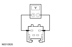 | Yes
INSTALL a new front seat track motor. REFER to Seat Track Motor — Front in this section. TEST the system for normal operation. DISCONNECT the battery ground cable. CONNECT driver seat side air bag C367 and driver seat safety belt buckle C3065. REPOWER the SRS . REFER to Section 501-20B . No GO to D4 . |
| D4 CHECK HORIZONTAL MOTOR CIRCUIT FOR AN OPEN AND SHORT TO GROUND | |
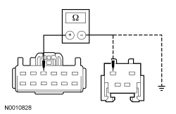 | Yes
GO to D5 . No REPAIR the circuit. TEST the system for normal operation. DISCONNECT the battery ground cable. CONNECT driver seat side air bag C367 and driver seat safety belt buckle C3065. REPOWER the SRS . REFER to Section 501-20B . |
| D5 CHECK HORIZONTAL MOTOR CIRCUIT FOR AN OPEN AND SHORT TO GROUND | |
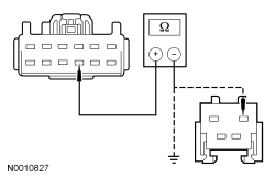 | Yes
INSTALL a new driver seat control switch. REFER to Seat Control Switch — Front in this section. TEST the system for normal operation. DISCONNECT the battery ground cable. CONNECT driver seat side air bag C367 and driver seat safety belt buckle C3065. REPOWER the SRS . REFER to Section 501-20B . No REPAIR the circuit. TEST the system for normal operation. DISCONNECT the battery ground cable. CONNECT driver seat side air bag C367 and driver seat safety belt buckle C3065. REPOWER the SRS . REFER to Section 501-20B . |
| D6 DETERMINE THE SEAT HEIGHT ADJUST FAILURE | |
| Yes
If only front height adjustment operates, GO to D7 . If only rear height adjustment operates, GO to D10 . No INSTALL a new driver seat control switch. REFER to Seat Control Switch — Front in this section. TEST the system for normal operation. DISCONNECT the battery ground cable. CONNECT driver seat side air bag C367 and driver seat safety belt buckle C3065. REPOWER the SRS . REFER to Section 501-20B . |
| D7 CHECK THE VOLTAGE TO THE DRIVER SEAT REAR HEIGHT MOTOR | |
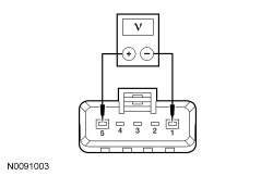 | Yes
INSTALL a new driver seat track assembly. REFER to Seat Track — Front in this section. TEST the system for normal operation. DISCONNECT the battery ground cable. CONNECT driver seat side air bag C367 and driver seat safety belt buckle C3065. REPOWER the SRS . REFER to Section 501-20B . No GO to D8 . |
| D8 CHECK THE REAR SEAT HEIGHT MOTOR CIRCUIT FOR AN OPEN AND SHORT TO GROUND | |
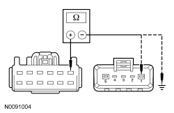 | Yes
GO to D9 . No REPAIR the circuit. TEST the system for normal operation. DISCONNECT the battery ground cable. CONNECT driver seat side air bag C367 and driver seat safety belt buckle C3065. REPOWER the SRS . REFER to Section 501-20B . |
| D9 CHECK THE REAR SEAT HEIGHT MOTOR CIRCUIT FOR AN OPEN AND SHORT TO GROUND | |
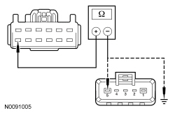 | Yes
INSTALL a new driver seat control switch. REFER to Seat Control Switch — Front in this section. TEST the system for normal operation. DISCONNECT the battery ground cable. CONNECT driver seat side air bag C367 and driver seat safety belt buckle C3065. REPOWER the SRS . REFER to Section 501-20B . No REPAIR the circuit. TEST the system for normal operation. DISCONNECT the battery ground cable. CONNECT driver seat side air bag C367 and driver seat safety belt buckle C3065. REPOWER the SRS . REFER to Section 501-20B . |
| D10 CHECK THE VOLTAGE TO THE DRIVER SEAT FRONT HEIGHT MOTOR | |
 | Yes
INSTALL a new driver seat track assembly. REFER to Seat Track — Front in this section. TEST the system for normal operation. DISCONNECT the battery ground cable. CONNECT driver seat side air bag C367 and driver seat safety belt buckle C3065. REPOWER the SRS . REFER to Section 501-20B . No GO to D11 . |
| D11 CHECK THE DRIVER SEAT FRONT HEIGHT MOTOR CIRCUIT FOR AN OPEN AND SHORT TO GROUND | |
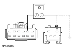 | Yes
GO to D12 . No REPAIR the circuit. TEST the system for normal operation. DISCONNECT the battery ground cable. CONNECT driver seat side air bag C367 and driver seat safety belt buckle C3065. REPOWER the SRS . REFER to Section 501-20B . |
| D12 CHECK THE DRIVER SEAT FRONT HEIGHT MOTOR CIRCUIT FOR AN OPEN AND A SHORT TO GROUND | |
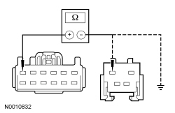 | Yes
INSTALL a new driver seat control switch. REFER to Seat Control Switch — Front in this section. TEST the system for normal operation. DISCONNECT the battery ground cable. CONNECT driver seat side air bag C367 and driver seat safety belt buckle C3065. REPOWER the SRS . REFER to Section 501-20B . No REPAIR the circuit. TEST the system for normal operation. DISCONNECT the battery ground cable. CONNECT driver seat side air bag C367 and driver seat safety belt buckle C3065. REPOWER the SRS . REFER to Section 501-20B . |
| D13 CHECK THE VOLTAGE TO THE DRIVER SEAT RECLINER MOTOR | |
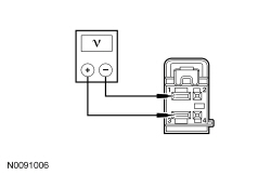 | Yes
INSTALL a new driver seat recliner motor. REFER to Seat Recliner Motor — Front in this section. TEST the system for normal operation. DISCONNECT the battery ground cable. CONNECT driver seat side air bag C367 and driver seat safety belt buckle C3065. REPOWER the SRS . REFER to Section 501-20B . No GO to D14 . |
| D14 CHECK DRIVER SEAT RECLINER MOTOR CIRCUIT FOR AN OPEN AND SHORT TO GROUND | |
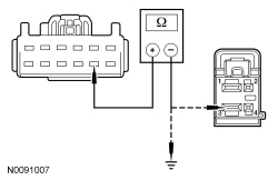 | Yes
GO to D15 . No REPAIR the circuit. TEST the system for normal operation. DISCONNECT the battery ground cable. CONNECT driver seat side air bag C367 and driver seat safety belt buckle C3065. REPOWER the SRS . REFER to Section 501-20B . |
| D15 CHECK DRIVER SEAT RECLINER MOTOR CIRCUIT FOR AN OPEN AND A SHORT TO GROUND | |
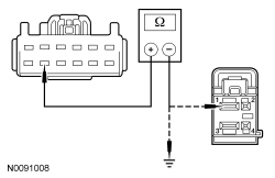 | Yes
INSTALL a new driver seat control switch. REFER to Seat Control Switch — Front in this section. TEST the system for normal operation. DISCONNECT the battery ground cable. CONNECT driver seat side air bag C367 and driver seat safety belt buckle C3065. REPOWER the SRS . REFER to Section 501-20B . No REPAIR the circuit. TEST the system for normal operation. DISCONNECT the battery ground cable. CONNECT driver seat side air bag C367 and driver seat safety belt buckle C3065. REPOWER the SRS . REFER to Section 501-20B . |
Pinpoint Test E: The Power Seat Does Not Move Horizontally/Vertically — Driver, Without Power Recliner
Refer to Wiring Diagrams Cell 120 , Power Seats for schematic and connector information.
The driver seat control switch is supplied battery voltage and ground. When pressed, the seat control switch supplies that voltage and ground to a power seat track motor to move the seat. When pressed in the opposite direction, the seat control switch reverses the polarity to that same power seat track motor, which moves the seat in the opposite direction. There are 3 power seat track motors that combine to move the seat cushion horizontally (forward/rearward) and vertically (front up/down and rear up/down). If a new motor needs to be installed, it is necessary to install an entire power seat track.
NOTE: The air bag warning indicator illuminates when the correct Restraints Control Module (RCM) fuse is removed and the ignition switch is on.
NOTE: The Supplemental Restraint System (SRS) must be fully operational and free of faults before releasing the vehicle to the customer.
| Test Step | Result / Action to Take |
|---|---|
| E1 CHECK HORIZONTAL MOTOR FOR CORRECT OPERATION | |
| Yes
GO to E5 . No GO to E2 . |
| E2 CHECK THE VOLTAGE TO THE DRIVER SEAT HORIZONTAL MOTOR | |
 | Yes
INSTALL a new front seat track motor. REFER to Seat Track Motor — Front in this section. TEST the system for normal operation. DISCONNECT the battery ground cable. CONNECT driver seat side air bag C367 and driver seat safety belt buckle C3065. REPOWER the SRS . REFER to Section 501-20B . No GO to E3 . |
| E3 CHECK THE HORIZONTAL MOTOR CIRCUIT FOR AN OPEN AND SHORT TO GROUND | |
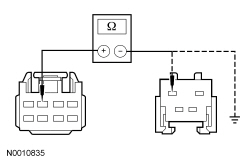 | Yes
GO to E4 . No REPAIR the circuit. TEST the system for normal operation. DISCONNECT the battery ground cable. CONNECT driver seat side air bag C367 and driver seat safety belt buckle C3065. REPOWER the SRS . REFER to Section 501-20B . |
| E4 CHECK THE HORIZONTAL MOTOR CIRCUIT FOR AN OPEN AND SHORT TO GROUND | |
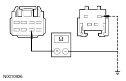 | Yes
INSTALL a new driver seat control switch. REFER to Seat Control Switch — Front in this section. TEST the system for normal operation. DISCONNECT the battery ground cable. CONNECT driver seat side air bag C367 and driver seat safety belt buckle C3065. REPOWER the SRS . REFER to Section 501-20B . No REPAIR the circuit. TEST the system for normal operation. DISCONNECT the battery ground cable. CONNECT driver seat side air bag C367 and driver seat safety belt buckle C3065. REPOWER the SRS . REFER to Section 501-20B . |
| E5 DETERMINE THE SEAT HEIGHT ADJUST FAILURE | |
| Yes
If only front height adjust operates, GO to E6 . If only rear height adjust operates, GO to E9 . No INSTALL a new driver seat control switch. REFER to Seat Control Switch — Front in this section. TEST the system for normal operation. DISCONNECT the battery ground cable. CONNECT driver seat side air bag C367 and driver seat safety belt buckle C3065. REPOWER the SRS . REFER to Section 501-20B . |
| E6 CHECK THE VOLTAGE TO THE DRIVER SEAT REAR HEIGHT MOTOR | |
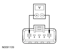 | Yes
INSTALL a new driver seat track assembly. REFER to Seat Track — Front in this section. TEST the system for normal operation. DISCONNECT the battery ground cable. CONNECT driver seat side air bag C367 and driver seat safety belt buckle C3065. REPOWER the SRS . REFER to Section 501-20B . No GO to E7 . |
| E7 CHECK THE DRIVER SEAT REAR HEIGHT MOTOR CIRCUIT FOR AN OPEN AND SHORT TO GROUND | |
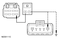 | Yes
GO to E8 . No REPAIR the circuit. TEST the system for normal operation. DISCONNECT the battery ground cable. CONNECT driver seat side air bag C367 and driver seat safety belt buckle C3065. REPOWER the SRS . REFER to Section 501-20B . |
| E8 CHECK THE DRIVER SEAT REAR HEIGHT MOTOR CIRCUIT FOR AN OPEN AND SHORT TO GROUND | |
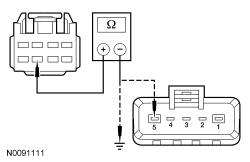 | Yes
INSTALL a new driver seat control switch. REFER to Seat Control Switch — Front in this section. TEST the system for normal operation. DISCONNECT the battery ground cable. CONNECT driver seat side air bag C367 and driver seat safety belt buckle C3065. REPOWER the SRS . REFER to Section 501-20B . No REPAIR the circuit. TEST the system for normal operation. DISCONNECT the battery ground cable. CONNECT driver seat side air bag C367 and driver seat safety belt buckle C3065. REPOWER the SRS . REFER to Section 501-20B . |
| E9 CHECK THE VOLTAGE TO THE DRIVER SEAT FRONT HEIGHT MOTOR | |
 | Yes
INSTALL a new driver seat track assembly. REFER to Seat Track — Front in this section. TEST the system for normal operation. DISCONNECT the battery ground cable. CONNECT driver seat side air bag C367 and driver seat safety belt buckle C3065. REPOWER the SRS . REFER to Section 501-20B . No GO to E10 . |
| E10 CHECK THE FRONT HEIGHT MOTOR CIRCUIT FOR AN OPEN AND SHORT TO GROUND | |
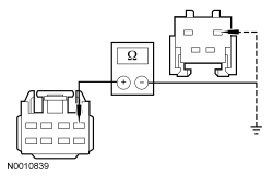 | Yes
GO to E11 . No REPAIR the circuit. TEST the system for normal operation. DISCONNECT the battery ground cable. CONNECT driver seat side air bag C367 and driver seat safety belt buckle C3065. REPOWER the SRS . REFER to Section 501-20B . |
| E11 CHECK THE FRONT HEIGHT MOTOR CIRCUIT FOR AN OPEN AND A SHORT TO GROUND | |
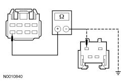 | Yes
INSTALL a new driver seat control switch. REFER to Seat Control Switch — Front in this section. TEST the system for normal operation. DISCONNECT the battery ground cable. CONNECT driver seat side air bag C367 and driver seat safety belt buckle C3065. REPOWER the SRS . REFER to Section 501-20B . No REPAIR the circuit. TEST the system for normal operation. DISCONNECT the battery ground cable. CONNECT driver seat side air bag C367 and driver seat safety belt buckle C3065. REPOWER the SRS . REFER to Section 501-20B . |
Pinpoint Test F: The Power Seat Does Not Move Horizontally/Vertically — Passenger, Without Power Recline
Refer to Wiring Diagrams Cell 120 , Power Seats for schematic and connector information.
The passenger seat control switch is supplied battery voltage and ground. When pressed, the seat control switch supplies that voltage and ground to a power seat track motor to move the seat. When pressed in the opposite direction, the seat control switch reverses the polarity to that same power seat track motor, which moves the seat in the opposite direction. There is a power seat track motor that moves the seat horizontally (forward/reverse) and a motor in the power recliner mechanism that moves the seat backrest forward or rearward.
NOTE: The air bag warning indicator illuminates when the correct Restraints Control Module (RCM) fuse is removed and the ignition switch is on.
NOTE: The Supplemental Restraint System (SRS) must be fully operational and free of faults before releasing the vehicle to the customer.
| Test Step | Result / Action to Take |
|---|---|
| F1 CHECK THE HORIZONTAL MOTOR FOR CORRECT OPERATION | |
| Yes
GO to F2 . No GO to F3 . |
| F2 DETERMINE THE SEAT HEIGHT ADJUST FAILURE | |
| Yes
If only front height adjust operates, GO to F6 . If only rear height adjust operates, GO to F9 . No INSTALL a new passenger seat control switch. REFER to Seat Control Switch — Front in this section. TEST the system for normal operation. |
| F3 CHECK THE VOLTAGE TO THE HORIZONTAL MOTOR | |
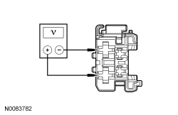 | Yes
INSTALL a new front seat track motor. REFER to Seat Track Motor — Front in this section. TEST the system for normal operation. DISCONNECT the battery ground cable. CONNECT passenger seat side air bag C337 and passenger safety belt buckle C3066. REPOWER the SRS . REFER to Section 501-20B . No GO to F4 . |
| F4 CHECK THE HORIZONTAL MOTOR CIRCUIT FOR AN OPEN | |
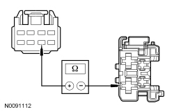 | Yes
GO to F5 . No REPAIR the circuit. TEST the system for normal operation. DISCONNECT the battery ground cable. CONNECT passenger seat side air bag C337 and passenger safety belt buckle C3066. REPOWER the SRS . REFER to Section 501-20B . |
| F5 CHECK THE HORIZONTAL MOTOR CIRCUIT FOR AN OPEN | |
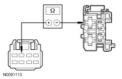 | Yes
INSTALL a new passenger seat control switch. REFER to Seat Control Switch — Front in this section. TEST the system for normal operation. DISCONNECT the battery ground cable. CONNECT passenger seat side air bag C337 and passenger safety belt buckle C3066. REPOWER the SRS . REFER to Section 501-20B . No REPAIR the circuit. TEST the system for normal operation. DISCONNECT the battery ground cable. CONNECT passenger seat side air bag C337 and passenger safety belt buckle C3066. REPOWER the SRS . REFER to Section 501-20B . |
| F6 CHECK THE VOLTAGE TO THE REAR HEIGHT MOTOR | |
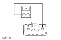 | Yes
INSTALL a new passenger seat track assembly. REFER to Seat Track — Front in this section. TEST the system for normal operation. DISCONNECT the battery ground cable. CONNECT passenger seat side air bag C337 and passenger safety belt buckle C3066. REPOWER the SRS . REFER to Section 501-20B . No GO to F7 . |
| F7 CHECK THE REAR HEIGHT MOTOR CIRCUIT FOR AN OPEN | |
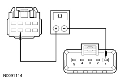 | Yes
GO to F8 . No REPAIR the circuit. TEST the system for normal operation. DISCONNECT the battery ground cable. CONNECT passenger seat side air bag C337 and passenger safety belt buckle C3066. REPOWER the SRS . REFER to Section 501-20B . |
| F8 CHECK THE REAR HEIGHT MOTOR CIRCUIT FOR AN OPEN | |
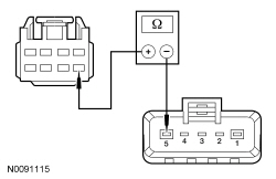 | Yes
INSTALL a new passenger seat control switch. REFER to Seat Control Switch — Front in this section. TEST the system for normal operation. DISCONNECT the battery ground cable. CONNECT passenger seat side air bag C337 and passenger safety belt buckle C3066. REPOWER the SRS . REFER to Section 501-20B . No REPAIR the circuit. TEST the system for normal operation. DISCONNECT the battery ground cable. CONNECT passenger seat side air bag C337 and passenger safety belt buckle C3066. REPOWER the SRS . REFER to Section 501-20B . |
| F9 CHECK THE VOLTAGE TO THE FRONT HEIGHT MOTOR | |
 | Yes
INSTALL a new passenger seat track assembly. REFER to Seat Track — Front in this section. TEST the system for normal operation. DISCONNECT the battery ground cable. CONNECT passenger seat side air bag C337 and passenger safety belt buckle C3066. REPOWER the SRS . REFER to Section 501-20B . No GO to F10 . |
| F10 CHECK THE FRONT HEIGHT MOTOR CIRCUIT FOR AN OPEN | |
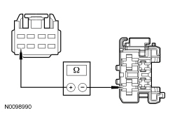 | Yes
GO to F11 . No REPAIR the circuit. TEST the system for normal operation. DISCONNECT the battery ground cable. CONNECT passenger seat side air bag C337 and passenger safety belt buckle C3066. REPOWER the SRS . REFER to Section 501-20B . |
| F11 CHECK THE FRONT HEIGHT MOTOR CIRCUIT FOR AN OPEN | |
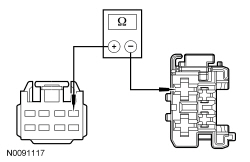 | Yes
INSTALL a new passenger seat control switch. REFER to Seat Control Switch — Front in this section. TEST the system for normal operation. DISCONNECT the battery ground cable. CONNECT passenger seat side air bag C337 and passenger safety belt buckle C3066. REPOWER the SRS . REFER to Section 501-20B . No REPAIR the circuit. TEST the system for normal operation. DISCONNECT the battery ground cable. CONNECT passenger seat side air bag C337 and passenger safety belt buckle C3066. REPOWER the SRS . REFER to Section 501-20B . |
Pinpoint Test G: The Power Seat is Inoperative — Passenger, With Power Recliner
Refer to Wiring Diagrams Cell 120 , Power Seats for schematic and connector information.
The passenger seat control switch is supplied battery voltage and ground. When pressed, the seat control switch supplies voltage and ground to a power seat track motor or power recliner motor to move the seat or backrest to the desired position. There are 3 power seat track motors that combine to move the seat cushion horizontally (forward/rearward) and vertically (front up/down and rear up/down). There is an additional motor in the power recliner mechanism to move the seat backrest forward and rearward. If a new motor needs to be installed, it is necessary to install an entire power seat track or power recliner mechanism.
NOTE: The air bag warning indicator illuminates when the correct Restraints Control Module (RCM) fuse is removed and the ignition switch is on.
NOTE: The Supplemental Restraint System (SRS) must be fully operational and free of faults before releasing the vehicle to the customer.
| Test Step | Result / Action to Take |
|---|---|
| G1 CHECK THE PASSENGER SEAT CONTROL SWITCH FOR VOLTAGE | |
 | Yes
GO to G2 . No VERIFY Battery Junction Box (BJB) fuse 42 (30A) is OK. If OK, REPAIR the circuit. If not OK, REFER to the Wiring Diagrams manual to identify possible causes of the circuit short. TEST the system for normal operation. DISCONNECT the battery ground cable. CONNECT passenger seat side air bag C337 and passenger safety belt buckle C3066. REPOWER the SRS . REFER to Section 501-20B . |
| G2 CHECK THE PASSENGER SEAT CONTROL SWITCH GROUND CIRCUIT FOR AN OPEN | |
 | Yes
INSTALL a new passenger seat control switch. REFER to Seat Control Switch — Front in this section. TEST the system for normal operation. DISCONNECT the battery ground cable. CONNECT passenger seat side air bag C337 and passenger safety belt buckle C3066. REPOWER the SRS . REFER to Section 501-20B . No REPAIR the circuit. TEST the system for normal operation. DISCONNECT the battery ground cable. CONNECT passenger seat side air bag C337 and passenger safety belt buckle C3066. REPOWER the SRS . REFER to Section 501-20B . |
Pinpoint Test H: The Power Seat Does Not Move Horizontally/Vertically/Recline — Passenger, With Power Recline
Refer to Wiring Diagrams Cell 120 , Power Seats for schematic and connector information.
The passenger seat control switch is supplied battery voltage and ground. When pressed, the seat control switch supplies that voltage and ground to a power seat track motor to move the seat. When pressed in the opposite direction, the seat control switch reverses the polarity to that same power seat track motor, which moves the seat in the opposite direction. There is a power seat track motor that moves the seat horizontally (forward/reverse) and a motor in the power recliner mechanism that moves the seat backrest forward or rearward.
NOTE: The air bag warning indicator illuminates when the correct Restraints Control Module (RCM) fuse is removed and the ignition is ON.
NOTE: The Supplemental Restraint System (SRS) must be fully operational and free of faults before releasing the vehicle to the customer.
| Test Step | Result / Action to Take |
|---|---|
| H1 CHECK THE HORIZONTAL MOTOR FOR CORRECT OPERATION | |
| Yes
GO to H2 . No GO to H3 . |
| H2 CHECK THE RECLINER MOTOR FOR CORRECT OPERATION | |
| Yes
GO to H6 . No GO to H13 . |
| H3 CHECK FOR VOLTAGE TO THE HORIZONTAL MOTOR | |
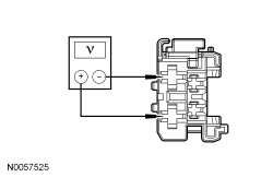 | Yes
INSTALL a new front seat track motor. REFER to Seat Track Motor — Front in this section. TEST the system for normal operation. DISCONNECT the battery ground cable. CONNECT passenger seat side air bag C337 and passenger safety belt buckle C3066. REPOWER the SRS . REFER to Section 501-20B . No GO to H4 . |
| H4 CHECK THE HORIZONTAL MOTOR CIRCUIT FOR AN OPEN | |
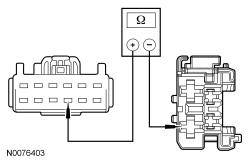 | Yes
GO to H5 . No REPAIR the circuit. TEST the system for normal operation. DISCONNECT the battery ground cable. CONNECT passenger seat side air bag C337 and passenger safety belt buckle C3066. REPOWER the SRS . REFER to Section 501-20B . |
| H5 CHECK THE HORIZONTAL MOTOR CIRCUIT FOR AN OPEN | |
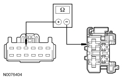 | Yes
INSTALL a new seat control switch. REFER to Seat Control Switch — Front in this section. TEST the system for normal operation. DISCONNECT the battery ground cable. CONNECT passenger seat side air bag C337 and passenger safety belt buckle C3066. REPOWER the SRS . REFER to Section 501-20B . No REPAIR the circuit. TEST the system for normal operation. DISCONNECT the battery ground cable. CONNECT passenger seat side air bag C337 and passenger safety belt buckle C3066. REPOWER the SRS . REFER to Section 501-20B . |
| H6 DETERMINE THE SEAT HEIGHT ADJUST FAILURE | |
| Yes
If only the front height adjust motor operates, GO to H7 . If only the rear height adjust motor operates, GO to H10 . No INSTALL a new seat control switch. REFER to Seat Control Switch — Front in this section. TEST the system for normal operation. |
| H7 CHECK FOR VOLTAGE TO THE REAR HEIGHT MOTOR | |
 | Yes
INSTALL a new seat track assembly. REFER to Seat Track — Front in this section. TEST the system for normal operation. DISCONNECT the battery ground cable. CONNECT passenger seat side air bag C337 and passenger safety belt buckle C3066. REPOWER the SRS . REFER to Section 501-20B . No GO to H8 . |
| H8 CHECK THE REAR HEIGHT MOTOR CIRCUIT FOR AN OPEN | |
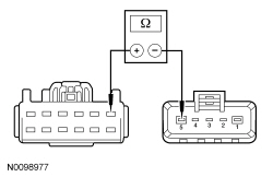 | Yes
GO to H9 . No REPAIR the circuit. TEST the system for normal operation. DISCONNECT the battery ground cable. CONNECT passenger seat side air bag C337 and passenger safety belt buckle C3066. REPOWER the SRS . REFER to Section 501-20B . |
| H9 CHECK THE REAR HEIGHT MOTOR CIRCUIT FOR AN OPEN | |
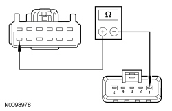 | Yes
INSTALL a new seat control switch. REFER to Seat Control Switch — Front in this section. TEST the system for normal operation. DISCONNECT the battery ground cable. CONNECT passenger seat side air bag C337 and passenger safety belt buckle C3066. REPOWER the SRS . REFER to Section 501-20B . No REPAIR the circuit. TEST the system for normal operation. DISCONNECT the battery ground cable. CONNECT passenger seat side air bag C337 and passenger safety belt buckle C3066. REPOWER the SRS . REFER to Section 501-20B . |
| H10 CHECK FOR VOLTAGE TO THE FRONT HEIGHT MOTOR | |
 | Yes
INSTALL a new seat track assembly. REFER to Seat Track — Front in this section. TEST the system for normal operation. DISCONNECT the battery ground cable. CONNECT passenger seat side air bag C337 and passenger safety belt buckle C3066. REPOWER the SRS . REFER to Section 501-20B . No GO to H11 . |
| H11 CHECK THE FRONT HEIGHT MOTOR CIRCUIT FOR AN OPEN | |
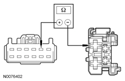 | Yes
GO to H12 . No REPAIR the circuit. TEST the system for normal operation. DISCONNECT the battery ground cable. CONNECT passenger seat side air bag C337 and passenger safety belt buckle C3066. REPOWER the SRS . REFER to Section 501-20B . |
| H12 CHECK THE FRONT HEIGHT MOTOR CIRCUIT FOR AN OPEN | |
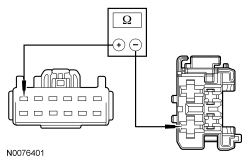 | Yes
INSTALL a new seat control switch. REFER to Seat Control Switch — Front in this section. TEST the system for normal operation. DISCONNECT the battery ground cable. CONNECT passenger seat side air bag C337 and passenger safety belt buckle C3066. REPOWER the SRS . REFER to Section 501-20B . No REPAIR the circuit. TEST the system for normal operation. DISCONNECT the battery ground cable. CONNECT passenger seat side air bag C337 and passenger safety belt buckle C3066. REPOWER the SRS . REFER to Section 501-20B . |
| H13 CHECK FOR VOLTAGE TO THE RECLINER MOTOR | |
 | Yes
INSTALL a new seat recliner motor. REFER to Seat Recliner Motor — Front in this section. TEST the system for normal operation. DISCONNECT the battery ground cable. CONNECT passenger seat side air bag C337 and passenger safety belt buckle C3066. REPOWER the SRS . REFER to Section 501-20B . No GO to H14 . |
| H14 CHECK THE RECLINER MOTOR CIRCUIT FOR AN OPEN | |
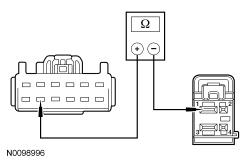 | Yes
GO to H15 . No REPAIR the circuit. TEST the system for normal operation. DISCONNECT the battery ground cable. CONNECT passenger seat side air bag C337 and passenger safety belt buckle C3066. REPOWER the SRS . REFER to Section 501-20B . |
| H15 CHECK THE RECLINER MOTOR CIRCUIT FOR AN OPEN | |
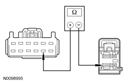 | Yes
INSTALL a new seat control switch. REFER to Seat Control Switch — Front in this section. TEST the system for normal operation. DISCONNECT the battery ground cable. CONNECT passenger seat side air bag C337 and passenger safety belt buckle C3066. REPOWER the SRS . REFER to Section 501-20B . No REPAIR the circuit. TEST the system for normal operation. DISCONNECT the battery ground cable. CONNECT passenger seat side air bag C337 and passenger safety belt buckle C3066. REPOWER the SRS . REFER to Section 501-20B . |
Pinpoint Test I: The Power Lumbar is Inoperative — Passenger
Refer to Wiring Diagrams Cell 120 , Power Seats for schematic and connector information.
Refer to Wiring Diagrams Cell 123 , Memory Seats for schematic and connector information.
The seat control switch is supplied battery voltage and ground at all times. When the lumbar button is pressed, voltage and ground are supplied to the power lumbar motor to move the lumbar assembly in the desired direction.
NOTE: The air bag warning indicator illuminates when the correct Restraints Control Module (RCM) fuse is removed and the ignition is ON.
NOTE: The Supplemental Restraint System (SRS) must be fully operational and free of faults before releasing the vehicle to the customer.
| Test Step | Result / Action to Take |
|---|---|
| I1 CHECK FOR VOLTAGE TO THE LUMBAR MOTOR | |
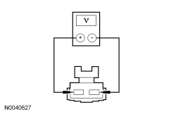 | Yes
INSTALL a new power lumbar assembly. REFER to Lumbar Assembly — Power in this section. TEST the system for normal operation. DISCONNECT the battery ground cable. CONNECT passenger seat side air bag C337 and passenger safety belt buckle C3066. REPOWER the SRS . REFER to Section 501-20B . No GO to I2 . |
| I2 CHECK THE LUMBAR MOTOR CIRCUITS FOR AN OPEN | |
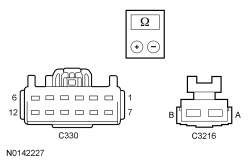 | Yes
INSTALL a new seat control switch. REFER to Seat Control Switch — Front in this section. TEST the system for normal operation. DISCONNECT the battery ground cable. CONNECT passenger seat side air bag C337 and passenger safety belt buckle C3066. REPOWER the SRS . REFER to Section 501-20B . No REPAIR the circuit. TEST the system for normal operation. DISCONNECT the battery ground cable. CONNECT passenger seat side air bag C337 and passenger safety belt buckle C3066. REPOWER the SRS . REFER to Section 501-20B . |
Pinpoint Test J: The Memory Seat is Inoperative/Does Not Operate Correctly — Does Not Operate Horizontally/Vertically/Recline
Refer to Wiring Diagrams Cell 123 , Memory Seats for schematic and connector information.
Refer to Wiring Diagrams Cell 149 , Component Testing for component testing.
The driver seat control switch is supplied battery voltage and ground. When pressed, the seat control switch supplies voltage and ground to the applicable Driver Seat Module (DSM) inputs. The DSM then supplies voltage and ground to the appropriate power seat track or recline motor based on the inputs received from the seat control switch. There are 3 power seat track motors that combine to move the seat horizontally (forward/backward) and vertically (front up/down and rear up/down). The recliner mechanism uses a single motor to pivot the seat backrest forward and backward.
Each motor in the memory seat track and recliner contain a Hall-effect position sensor. The DSM supplies a shared signal feed circuit to each sensor. Each position sensor sends a signal pulse back to the DSM to monitor the position of the power seat and seat backrest. The DSM uses this information to return the seat to a stored pre-programmed position when pressing the memory SET switch or a Remote Keyless Entry (RKE). For information on programming memory positions or recalling a stored memory position, refer to Memory Position Programming in this section.
The following pinpoint test diagnoses a memory seat that does not operate in one or more directions when using the seat control switch. If the memory seat moves in all directions using the seat control switch, but does not operate using the memory SET switch, GO to Pinpoint Test K .
| DTC Description | Fault Trigger Conditions |
|---|---|
| During self-test, the Driver Seat Module (DSM) attempts to operate the appropriate seat track motor and uses the motor position sensor to monitor movement. If no motor movement is sensed, the DTC is set. The DSM will retry motor operation on the next activation of the seat control switch. If no movement continues to be monitored after 250 milliseconds, the DSM disables the output. |
| During self-test, the DSM attempts to operate the recliner motor and uses the recliner motor position sensor to monitor movement. If no motor movement is sensed, the DTC is set. The DSM will retry motor operation on the next activation of the seat control switch. If no motor movement is still monitored after 250 milliseconds, the DSM disables the output. |
| If voltage is sensed on the switch input circuit during the DSM self-test, the DTC is set. If voltage is sensed on the input circuit for greater than 2 minutes, the DTC is set as continuous. With the DTC set, any input signal on the circuit is ignored. |
| If voltage is sensed on the switch input circuit during the DSM self-test, the DTC is set. If voltage is sensed on the input circuit for greater than 2 minutes, the DTC is set as continuous. With the DTC set, any input signal on the circuit is ignored. |
| If voltage is sensed on the switch input circuit during the DSM self-test, the DTC is set. If voltage is sensed on the input circuit for greater than 2 minutes, the DTC is set as continuous. With the DTC set, any input signal on the circuit is ignored. |
| If voltage is sensed on the switch input circuit during the DSM self-test, the DTC is set. If voltage is sensed on the input circuit for greater than 2 minutes, the DTC is set as continuous. With the DTC set, any input signal on the circuit is ignored. |
NOTE: The air bag warning indicator illuminates when the correct Restraints Control Module (RCM) fuse is removed and the ignition is ON.
NOTE: The Supplemental Restraint System (SRS) must be fully operational and free of faults before releasing the vehicle to the customer.
NOTE: If a new DSM has been installed, all memory seat soft stops must be reset. If a new seat track or recline motor has been installed, only reset the soft stops for that component being installed new. To reset the soft stops, refer to Principles of Operation in this section.
NOTE: Refer to Description and Operation, Intelligent Access with Push Button Start in Section 419-01A to review the procedures for achieving the various ignition states (ignition OFF, ignition in ACCESSORY, ignition ON, ignition START) on vehicles with this feature.
| Test Step | Result / Action to Take | |||||||||||||||||||||||||||
|---|---|---|---|---|---|---|---|---|---|---|---|---|---|---|---|---|---|---|---|---|---|---|---|---|---|---|---|---|
| J1 RETRIEVE THE DSM DTCs | ||||||||||||||||||||||||||||
| Yes
If DTCs B1663, B1664, B1665 and B1666 are all retrieved, GO to J10 . If DTC B1663, GO to J20 . If DTC B1664, GO to J23 . If DTC B1665, GO to J26 . If DTC B1666, GO to J29 . If DTC B1703, B1707, B1711, B1715, B1719, B1723, B1727 or B1731, GO to J3 . If DTC B1342, INSTALL a new DSM . REFER to Driver Seat Module (DSM) in this section. CLEAR the DTCs. REPEAT the self-test. For any other DSM DTCs, REFER to the Driver Seat Module (DSM) DTC Chart. No GO to J2 . | |||||||||||||||||||||||||||
| J2 CHECK THE DSM SEAT CONTROL SWITCH PIDs | ||||||||||||||||||||||||||||
| Yes
GO to J9 . No VERIFY Body Control Module (BCM) fuse 2 (15A) is OK. If the fuse fails while operating the seat control switch, DISCONNECT the seat control switch C369 and GO to J7 . If the fuse is OK, GO to J3 . | |||||||||||||||||||||||||||
| J3 CHECK THE SEAT CONTROL SWITCH | ||||||||||||||||||||||||||||
| Yes
GO to J4 . No INSTALL a new seat control switch. REFER to Seat Control Switch — Front in this section.CLEAR the DTCs. REPEAT the self-test | |||||||||||||||||||||||||||
| J4 CHECK FOR VOLTAGE TO THE SEAT CONTROL SWITCH | ||||||||||||||||||||||||||||
 | Yes
GO to J5 . No VERIFY Body Control Module (BCM) fuse 2 (15A) is OK. If OK, REPAIR the circuit. If not OK, REFER to the Wiring Diagrams manual to identify the possible causes of the circuit short. CLEAR the DTCs. REPEAT the self-test. DISCONNECT the battery ground cable. CONNECT driver seat side air bag C367 and driver seat safety belt buckle C3065. REPOWER the SRS . REFER to Section 501-20B . | |||||||||||||||||||||||||||
| J5 CHECK THE SEAT CONTROL SWITCH GROUND CIRCUIT FOR AN OPEN | ||||||||||||||||||||||||||||
 | Yes
GO to J6 . No REPAIR the circuit. CLEAR the DTCs. REPEAT the self-test. DISCONNECT the battery ground cable. CONNECT driver seat side air bag C367 and driver seat safety belt buckle C3065. REPOWER the SRS . REFER to Section 501-20B . | |||||||||||||||||||||||||||
| J6 CHECK THE CIRCUITS BETWEEN THE SEAT CONTROL SWITCH AND DSM FOR A SHORT TO VOLTAGE | ||||||||||||||||||||||||||||
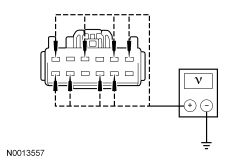 | Yes
REPAIR the circuit(s). CLEAR the DTCs. REPEAT the self-test. DISCONNECT the battery ground cable. CONNECT driver seat side air bag C367 and driver seat safety belt buckle C3065. REPOWER the SRS . REFER to Section 501-20B . No GO to J7 . | |||||||||||||||||||||||||||
| J7 CHECK THE CIRCUITS BETWEEN THE SEAT CONTROL SWITCH AND DSM FOR A SHORT TO GROUND | ||||||||||||||||||||||||||||
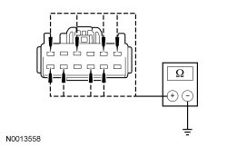 | Yes
GO to J8 . No REPAIR the circuit(s). CLEAR the DTCs. REPEAT the self-test. DISCONNECT the battery ground cable. CONNECT driver seat side air bag C367 and driver seat safety belt buckle C3065. REPOWER the SRS . REFER to Section 501-20B . | |||||||||||||||||||||||||||
| J8 CHECK THE CIRCUITS BETWEEN THE SEAT CONTROL SWITCH AND DSM FOR AN OPEN | ||||||||||||||||||||||||||||
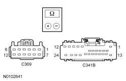 | Yes
INSTALL a new DSM . REFER to Driver Seat Module (DSM) in this section. CLEAR the DTCs. REPEAT the self-test. DISCONNECT the battery ground cable. CONNECT driver seat side air bag C367 and driver seat safety belt buckle C3065. REPOWER the SRS . REFER to Section 501-20B . No REPAIR the circuit(s). CLEAR the DTCs. REPEAT the self-test. DISCONNECT the battery ground cable. CONNECT driver seat side air bag C367 and driver seat safety belt buckle C3065. REPOWER the SRS . REFER to Section 501-20B . | |||||||||||||||||||||||||||
| J9 CHECK THE SEAT TRACK OPERATION USING DSM ACTIVE COMMANDS AND PIDs | ||||||||||||||||||||||||||||
| Yes
The condition may be intermittent. CHECK for causes of an intermittent concern, particularly the pins and terminals of electrical connectors that were disconnected. Do not install any new components at this time. Components should only be installed when directed to do so in the pinpoint test. REPAIR any intermittent wiring, terminal or connector concerns found. CLEAR the DTCs. REPEAT the self-test. DISCONNECT the battery ground cable. CONNECT driver seat side air bag C367 and driver seat safety belt buckle C3065. REPOWER the SRS . REFER to Section 501-20B . No If no seat movement, GO to J10 . If no front vertical seat movement, GO to J20 . If no rear vertical seat movement, GO to J23 . If no horizontal seat movement, GO to J26 . If no recline seat movement, GO to J29 . | |||||||||||||||||||||||||||
| J10 CHECK FOR VOLTAGE TO THE DSM | ||||||||||||||||||||||||||||
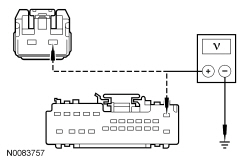 | Yes
GO to J11 . No VERIFY Battery Junction Box (BJB) fuse 23 (30A) or BCM fuse 7 (7.5A) are OK. If OK, REPAIR the circuit. If not OK, REFER to the Wiring Diagrams manual to identify the possible causes of the circuit short. CLEAR the DTCs. REPEAT the self-test. DISCONNECT the battery ground cable. CONNECT driver seat side air bag C367 and driver seat safety belt buckle C3065. REPOWER the SRS . REFER to Section 501-20B . | |||||||||||||||||||||||||||
| J11 CHECK THE DSM GROUND CIRCUITS FOR AN OPEN | ||||||||||||||||||||||||||||
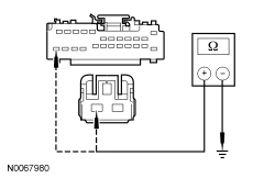 | Yes
GO to J12 . No REPAIR the circuit. CLEAR the DTCs. REPEAT the self-test. DISCONNECT the battery ground cable. CONNECT driver seat side air bag C367 and driver seat safety belt buckle C3065. REPOWER the SRS . REFER to Section 501-20B . | |||||||||||||||||||||||||||
| J12 CHECK THE FRONT HEIGHT MOTOR CIRCUITS FOR A SHORT TO GROUND | ||||||||||||||||||||||||||||
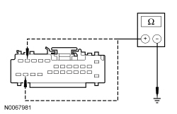 | Yes
GO to J14 . No GO to J13 . | |||||||||||||||||||||||||||
| J13 CHECK THE FRONT HEIGHT MOTOR CIRCUITS FOR A SHORT TO GROUND | ||||||||||||||||||||||||||||
 | Yes
INSTALL a new driver seat track assembly. REFER to Seat Track — Front in this section. CLEAR the DTCs. REPEAT the self-test. DISCONNECT the battery ground cable. CONNECT driver seat side air bag C367 and driver seat safety belt buckle C3065. REPOWER the SRS . REFER to Section 501-20B . No REPAIR the circuit(s). CLEAR the DTCs. REPEAT the self-test. DISCONNECT the battery ground cable. CONNECT driver seat side air bag C367 and driver seat safety belt buckle C3065. REPOWER the SRS . REFER to Section 501-20B . | |||||||||||||||||||||||||||
| J14 CHECK THE REAR HEIGHT MOTOR CIRCUITS FOR A SHORT TO GROUND | ||||||||||||||||||||||||||||
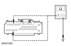 | Yes
GO to J16 . No GO to J15 . | |||||||||||||||||||||||||||
| J15 CHECK THE REAR HEIGHT MOTOR CIRCUITS FOR A SHORT TO GROUND | ||||||||||||||||||||||||||||
 | Yes
INSTALL a new driver seat track assembly. REFER to Seat Track — Front in this section. CLEAR the DTCs. REPEAT the self-test. DISCONNECT the battery ground cable. CONNECT driver seat side air bag C367 and driver seat safety belt buckle C3065. REPOWER the SRS . REFER to Section 501-20B . No REPAIR the circuit(s). CLEAR the DTCs. REPEAT the self-test. DISCONNECT the battery ground cable. CONNECT driver seat side air bag C367 and driver seat safety belt buckle C3065. REPOWER the SRS . REFER to Section 501-20B . | |||||||||||||||||||||||||||
| J16 CHECK THE HORIZONTAL MOTOR CIRCUITS FOR A SHORT TO GROUND | ||||||||||||||||||||||||||||
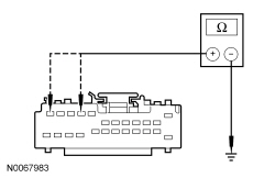 | Yes
GO to J18 . No GO to J17 . | |||||||||||||||||||||||||||
| J17 CHECK THE HORIZONTAL MOTOR CIRCUITS FOR A SHORT TO GROUND | ||||||||||||||||||||||||||||
 | Yes
INSTALL a new front seat track motor. REFER to Seat Track Motor — Front in this section. CLEAR the DTCs. REPEAT the self-test. DISCONNECT the battery ground cable. CONNECT driver seat side air bag C367 and driver seat safety belt buckle C3065. REPOWER the SRS . REFER to Section 501-20B . No REPAIR the circuit(s). CLEAR the DTCs. REPEAT the self-test. DISCONNECT the battery ground cable. CONNECT driver seat side air bag C367 and driver seat safety belt buckle C3065. REPOWER the SRS . REFER to Section 501-20B . | |||||||||||||||||||||||||||
| J18 CHECK THE RECLINER MOTOR CIRCUITS FOR A SHORT TO GROUND | ||||||||||||||||||||||||||||
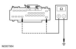 | Yes
INSTALL a new DSM . REFER to Driver Seat Module (DSM) in this section. CLEAR the DTCs. REPEAT the self-test. DISCONNECT the battery ground cable. CONNECT driver seat side air bag C367 and driver seat safety belt buckle C3065. REPOWER the SRS . REFER to Section 501-20B . No GO to J19 . | |||||||||||||||||||||||||||
| J19 CHECK THE RECLINER MOTOR CIRCUITS FOR A SHORT TO GROUND | ||||||||||||||||||||||||||||
 | Yes
INSTALL a new driver seat recliner motor. REFER to Seat Recliner Motor — Front in this section. CLEAR the DTCs. REPEAT the self-test. DISCONNECT the battery ground cable. CONNECT driver seat side air bag C367 and driver seat safety belt buckle C3065. REPOWER the SRS . REFER to Section 501-20B . No REPAIR the circuit(s). CLEAR the DTCs. REPEAT the self-test. DISCONNECT the battery ground cable. CONNECT driver seat side air bag C367 and driver seat safety belt buckle C3065. REPOWER the SRS . REFER to Section 501-20B . | |||||||||||||||||||||||||||
| J20 CHECK THE FRONT HEIGHT MOTOR FOR CORRECT OPERATION USING ACTIVE COMMANDS | ||||||||||||||||||||||||||||
 | Yes
INSTALL a new driver seat track assembly. REFER to Seat Track — Front in this section. CLEAR the DTCs. REPEAT the self-test. DISCONNECT the battery ground cable. CONNECT driver seat side air bag C367 and driver seat safety belt buckle C3065. REPOWER the SRS . REFER to Section 501-20B . No GO to J21 . | |||||||||||||||||||||||||||
| J21 CHECK THE FRONT HEIGHT MOTOR CIRCUITS FOR A SHORT TO VOLTAGE | ||||||||||||||||||||||||||||
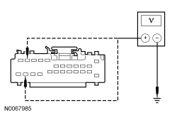 | Yes
REPAIR the circuit(s). CLEAR the DTCs. REPEAT the self-test. DISCONNECT the battery ground cable. CONNECT driver seat side air bag C367 and driver seat safety belt buckle C3065. REPOWER the SRS . REFER to Section 501-20B . No GO to J22 . | |||||||||||||||||||||||||||
| J22 CHECK THE FRONT HEIGHT MOTOR CIRCUITS FOR AN OPEN | ||||||||||||||||||||||||||||
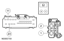 | Yes
INSTALL a new DSM . REFER to Driver Seat Module (DSM) in this section. CLEAR the DTCs. REPEAT the self-test. DISCONNECT the battery ground cable. CONNECT driver seat side air bag C367 and driver seat safety belt buckle C3065. REPOWER the SRS . REFER to Section 501-20B . No REPAIR the circuit(s). CLEAR the DTCs. REPEAT the self-test. DISCONNECT the battery ground cable. CONNECT driver seat side air bag C367 and driver seat safety belt buckle C3065. REPOWER the SRS . REFER to Section 501-20B . | |||||||||||||||||||||||||||
| J23 CHECK THE REAR HEIGHT MOTOR FOR CORRECT OPERATION USING ACTIVE COMMANDS | ||||||||||||||||||||||||||||
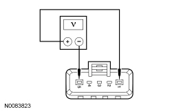 | Yes
INSTALL a new driver seat track assembly. REFER to Seat Track — Front in this section. CLEAR the DTCs. REPEAT the self-test. DISCONNECT the battery ground cable. CONNECT driver seat side air bag C367 and driver seat safety belt buckle C3065. REPOWER the SRS . REFER to Section 501-20B . No GO to J24 . | |||||||||||||||||||||||||||
| J24 CHECK THE REAR HEIGHT MOTOR CIRCUITS FOR A SHORT TO VOLTAGE | ||||||||||||||||||||||||||||
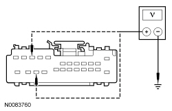 | Yes
REPAIR the circuit(s). CLEAR the DTCs. REPEAT the self-test. DISCONNECT the battery ground cable. CONNECT driver seat side air bag C367 and driver seat safety belt buckle C3065. REPOWER the SRS . REFER to Section 501-20B . No GO to J25 . | |||||||||||||||||||||||||||
| J25 CHECK THE REAR HEIGHT MOTOR CIRCUITS FOR AN OPEN | ||||||||||||||||||||||||||||
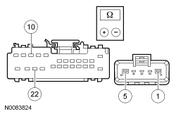 | Yes
INSTALL a new DSM . REFER to Driver Seat Module (DSM) in this section. CLEAR the DTCs. REPEAT the self-test. DISCONNECT the battery ground cable. CONNECT driver seat side air bag C367 and driver seat safety belt buckle C3065. REPOWER the SRS . REFER to Section 501-20B . No REPAIR the circuit(s). CLEAR the DTCs. REPEAT the self-test. DISCONNECT the battery ground cable. CONNECT driver seat side air bag C367 and driver seat safety belt buckle C3065. REPOWER the SRS . REFER to Section 501-20B . | |||||||||||||||||||||||||||
| J26 CHECK THE HORIZONTAL MOTOR FOR CORRECT OPERATION USING ACTIVE COMMANDS | ||||||||||||||||||||||||||||
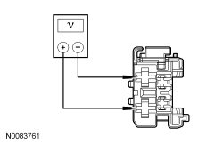 | Yes
INSTALL a new front seat track motor. REFER to Seat Track Motor — Front in this section. CLEAR the DTCs. REPEAT the self-test. DISCONNECT the battery ground cable. CONNECT driver seat side air bag C367 and driver seat safety belt buckle C3065. REPOWER the SRS . REFER to Section 501-20B . No GO to J27 . | |||||||||||||||||||||||||||
| J27 CHECK THE HORIZONTAL MOTOR CIRCUITS FOR A SHORT TO VOLTAGE | ||||||||||||||||||||||||||||
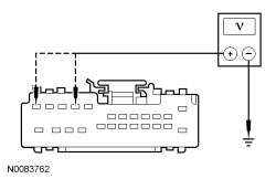 | Yes
REPAIR the circuit(s). CLEAR the DTCs. CLEAR the DTCs. DISCONNECT the battery ground cable. CONNECT driver seat side air bag C367 and driver seat safety belt buckle C3065. REPOWER the SRS . REFER to Section 501-20B . No GO to J28 . | |||||||||||||||||||||||||||
| J28 CHECK THE HORIZONTAL MOTOR CIRCUITS FOR AN OPEN | ||||||||||||||||||||||||||||
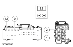 | Yes
INSTALL a new DSM . REFER to Driver Seat Module (DSM) in this section. CLEAR the DTCs. REPEAT the self-test. DISCONNECT the battery ground cable. CONNECT driver seat side air bag C367 and driver seat safety belt buckle C3065. REPOWER the SRS . REFER to Section 501-20B . No REPAIR the circuit(s). CLEAR the DTCs. REPEAT the self-test. DISCONNECT the battery ground cable. CONNECT driver seat side air bag C367 and driver seat safety belt buckle C3065. REPOWER the SRS . REFER to Section 501-20B . | |||||||||||||||||||||||||||
| J29 CHECK VOLTAGE AT THE RECLINER MOTOR USING DSM RECLINER MOTOR PIDs | ||||||||||||||||||||||||||||
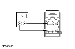 | Yes
INSTALL a new driver seat recliner motor. REFER to Seat Recliner Motor — Front in this section. CLEAR the DTCs. REPEAT the self-test. DISCONNECT the battery ground cable. CONNECT driver seat side air bag C367 and driver seat safety belt buckle C3065. REPOWER the SRS . REFER to Section 501-20B . No GO to J30 . | |||||||||||||||||||||||||||
| J30 CHECK THE RECLINER MOTOR CIRCUITS FOR A SHORT TO VOLTAGE | ||||||||||||||||||||||||||||
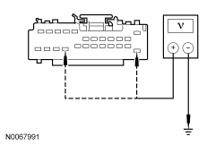 | Yes
REPAIR the circuit(s). CLEAR the DTCs. REPEAT the self-test. DISCONNECT the battery ground cable. CONNECT driver seat side air bag C367 and driver seat safety belt buckle C3065. REPOWER the SRS . REFER to Section 501-20B . No GO to J31 . | |||||||||||||||||||||||||||
| J31 CHECK THE RECLINER MOTOR CIRCUITS FOR AN OPEN | ||||||||||||||||||||||||||||
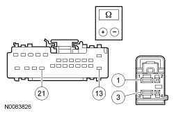 | Yes
INSTALL a new DSM . REFER to Driver Seat Module (DSM) in this section. CLEAR the DTCs. REPEAT the self-test. DISCONNECT the battery ground cable. CONNECT driver seat side air bag C367 and driver seat safety belt buckle C3065. REPOWER the SRS . REFER to Section 501-20B . No REPAIR the circuit(s). CLEAR the DTCs. REPEAT the self-test. DISCONNECT the battery ground cable. CONNECT driver seat side air bag C367 and driver seat safety belt buckle C3065. REPOWER the SRS . REFER to Section 501-20B . |
Pinpoint Test K: The Memory Seat Does Not Operate Correctly — Does Not Operate Using the Memory SET Switch
Refer to Wiring Diagrams Cell 123 , Memory Seats for schematic and connector information.
Each motor in the memory seat track and recliner mechanism contains a Hall-effect position sensor. The Driver Seat Module (DSM) supplies a voltage signal to each sensor. Each position sensor sends a signal pulse back to the DSM to monitor the position of the power seat and seat backrest. The DSM stores the sensor position data when a SET command is received and uses this information to return the seat to the stored position when a recall command is received.
The memory SET switch is supplied a ground circuit. When SET button 1 or 2 is pressed, the memory SET switch supplies ground to the Driver Door Module (DDM) input circuit. The DDM communicates a memory SET command to the DSM on the Medium Speed Controller Area Network (MS-CAN). The DSM then supplies voltage and ground to the power seat track motors and power recliner motor to move the seat to the stored position. For information on programming memory positions or recalling a stored memory position, refer to Memory Position Programming in this section.
The following pinpoint test diagnoses a memory seat that does not operate correctly using the memory SET switch. If the memory seat does not move in all directions using the seat control switch, GO to Pinpoint Test J .
| DTC Description | Fault Trigger Conditions |
|---|---|
| If any activity is sensed on the switch input circuit during the Driver Door Module (DDM) self-test, the DTC is set. If activity is sensed on the input circuit for greater than 2 minutes, the DTC is set as continuous. With the DTC set, any input signal on the circuit is ignored. |
| During self-test the DSM attempts to operate the seat track motors and uses the motor position sensor to monitor movement. If no motor movement is sensed, a DTC is set. The DSM will retry motor operation on the next activation of the seat control switch. If no movement continues to be monitored after 250 milliseconds, the DSM disables the output. |
| During self-test the DSM attempts to operate the recliner motor and uses the recliner motor position sensor to monitor movement. If no motor movement is sensed, the DTC is set. The DSM will retry motor operation on the next activation of the seat control switch. If no motor movement is still monitored after 250 milliseconds, the DSM disables the output. |
| If a short to voltage condition is present on the affected motor position sensor (Hall-effect) feedback circuit, the DTC is set. After a DTC is set, a memory recall is not possible but the seat control switch can operate the associated motor in one second increments. |
| If a short to ground or open condition is present on the affected motor position sensor (Hall effect) feedback circuit, the DTC is set. After a DTC is set, a memory recall is not possible but the seat control switch can operate the associated motor in one second increments. |
NOTICE: Use the correct probe adapter(s) from the Flex Probe Kit when taking measurements. Failure to use the correct probe adapter(s) may damage the connector.
NOTE: The air bag warning indicator illuminates when the correct Restraints Control Module (RCM) fuse is removed and the ignition is ON.
NOTE: The Supplemental Restraint System (SRS) must be fully operational and free of faults before releasing the vehicle to the customer.
NOTE: If a new DSM has been installed, all memory seat soft stops must be reset. If a new seat track or recline motor has been installed, only reset the soft stops for that component being installed new. To reset the soft stops, refer to Principles of Operation in this section.
NOTE: Verify good battery condition before diagnosing the memory seat system. Poor battery condition may interfere with memory seat operation, even if vehicle starting is possible.
NOTE: Verify the PID(s) states agree with the ignition and transmission gear selector in all positions before proceeding with memory seat diagnosis.
| Test Step | Result / Action to Take | |||||||||
|---|---|---|---|---|---|---|---|---|---|---|
| K1 CHECK PCM TRANSMISSION RANGE (TR) PID STATES | ||||||||||
| Yes
GO to K2 . No To diagnose a transmission gear selector (PRNDL) status concern, REFER to Section 307-01 . | |||||||||
| K2 CHECK DDM IGNITION KEY STATUS (KEYST) PID STATES | ||||||||||
| Yes
GO to K3 . No To diagnose an ignition status concern, REFER to Section 211-05 . | |||||||||
| K3 RETRIEVE THE DSM DTCs | ||||||||||
| Yes
If DTCs B1952, B1956, B1960 and B1964 are all retrieved, GO to K10 . If DTCs B1953, B1957, B1961 and B1965 are all retrieved, GO to K10 . If DTC B1534 or B1538, GO to K5 . If DTC B1956, B1957 or B1663, GO to K11 . If DTC B1952, B1953 or B1664, GO to K14 . If DTC B1665, B1964 or B1965, GO to K17 . If DTC B1960, B1961, or B1666, GO to K20 . If DTC B1342, INSTALL a new DSM . REFER to Driver Seat Module (DSM) in this section. CLEAR the DTCs. REPEAT the self-test. For any other DSM DTCs, REFER to the Driver Seat Module (DSM) DTC Chart. For any other Driver Door Module (DDM) DTCs, REFER to the Driver Door Module (DDM) DTC Chart. No GO to K4 . | |||||||||
| K4 MONITOR DSM PIDs AND CHECK FOR CORRECT MEMORY SET SWITCH INPUTS | ||||||||||
| Yes
GO to K10 . No GO to K5 . | |||||||||
| K5 CHECK THE MEMORY SET SWITCH | ||||||||||
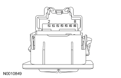 | Yes
GO to K6 . No INSTALL a new memory SET switch. REFER to Memory Set Switch in this section. CLEAR the DTCs. REPEAT the self-test. | |||||||||
| K6 CHECK THE MEMORY SWITCH GROUND CIRCUIT FOR AN OPEN | ||||||||||
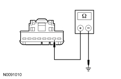 | Yes
GO to K7 . No REPAIR the circuit. CLEAR the DTCs. REPEAT the self-test. | |||||||||
| K7 CHECK CIRCUITS FOR A SHORT TO VOLTAGE | ||||||||||
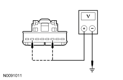 | Yes
REPAIR the circuit(s). CLEAR the DTCs. REPEAT the self-test. No GO to K8 . | |||||||||
| K8 CHECK THE MEMORY SET SWITCH CIRCUITS FOR A SHORT TO GROUND | ||||||||||
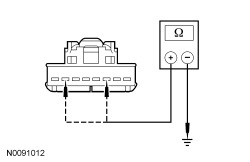 | Yes
GO to K9 . No REPAIR the circuit(s). CLEAR the DTCs. REPEAT the self-test. | |||||||||
| K9 CHECK MEMORY SET SWITCH CIRCUITS FOR AN OPEN | ||||||||||
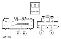 | Yes
INSTALL a new DDM . REFER to Section 501-14A or Section 501-14B . CLEAR the DTCs. REPEAT the self-test. No REPAIR the circuit(s). CLEAR the DTCs. REPEAT the self-test. | |||||||||
| K10 MONITOR THE DSM PIDs | ||||||||||
| Yes
INSTALL a new DSM . REFER to Driver Seat Module (DSM) in this section. CLEAR the DTCs. REPEAT the self-test. No If front up/down position sensor PID value indicates not present, GO to K11 . If rear up/down position sensor PID value indicates not present, GO to K14 . If forward/rearward position sensor PID value indicates not present, GO to K17 . If recline position sensor PID value indicates not present, GO to K17 . | |||||||||
| K11 CHECK FRONT HEIGHT MOTOR SENSOR CIRCUITS FOR A SHORT TO VOLTAGE | ||||||||||
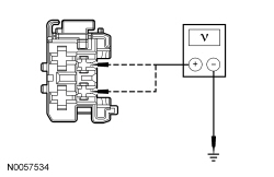 | Yes
REPAIR the circuit(s). CLEAR the DTCs. REPEAT the self-test. DISCONNECT the battery ground cable. CONNECT driver seat side air bag C367 and driver seat safety belt buckle C3065. REPOWER the SRS . REFER to Section 501-20B . No GO to K12 . | |||||||||
| K12 CHECK FRONT HEIGHT MOTOR SENSOR CIRCUITS FOR A SHORT TO GROUND | ||||||||||
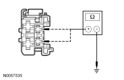 | Yes
GO to K13 . No REPAIR the circuit(s). CLEAR the DTCs. REPEAT the self-test. DISCONNECT the battery ground cable. CONNECT driver seat side air bag C367 and driver seat safety belt buckle C3065. REPOWER the SRS . REFER to Section 501-20B . | |||||||||
| K13 CHECK THE FRONT HEIGHT MOTOR SENSOR CIRCUITS FOR AN OPEN | ||||||||||
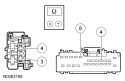 | Yes
INSTALL a new driver seat track assembly. REFER to Seat Track — Front in this section. CLEAR the DTCs. REPEAT the self-test. DISCONNECT the battery ground cable. CONNECT driver seat side air bag C367 and driver seat safety belt buckle C3065. REPOWER the SRS . REFER to Section 501-20B . No REPAIR the circuit(s). CLEAR the DTCs. REPEAT the self-test. DISCONNECT the battery ground cable. CONNECT driver seat side air bag C367 and driver seat safety belt buckle C3065. REPOWER the SRS . REFER to Section 501-20B . | |||||||||
| K14 CHECK THE REAR HEIGHT MOTOR SENSOR CIRCUITS FOR A SHORT TO VOLTAGE | ||||||||||
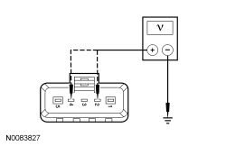 | Yes
REPAIR the circuit(s). CLEAR the DTCs. REPEAT the self-test. DISCONNECT the battery ground cable. CONNECT driver seat side air bag C367 and driver seat safety belt buckle C3065. REPOWER the SRS . REFER to Section 501-20B . No GO to K15 . | |||||||||
| K15 CHECK THE REAR HEIGHT MOTOR SENSOR CIRCUITS FOR A SHORT TO GROUND | ||||||||||
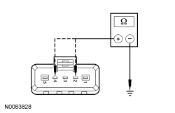 | Yes
GO to K16 . No REPAIR the circuit(s). CLEAR the DTCs. REPEAT the self-test. DISCONNECT the battery ground cable. CONNECT driver seat side air bag C367 and driver seat safety belt buckle C3065. REPOWER the SRS . REFER to Section 501-20B . | |||||||||
| K16 CHECK THE REAR HEIGHT MOTOR SENSOR CIRCUITS FOR AN OPEN | ||||||||||
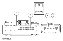 | Yes
INSTALL a new driver seat track assembly. REFER to Seat Track — Front in this section. CLEAR the DTCs. REPEAT the self-test. DISCONNECT the battery ground cable. CONNECT driver seat side air bag C367 and driver seat safety belt buckle C3065. REPOWER the SRS . REFER to Section 501-20B . No REPAIR the circuit(s). CLEAR the DTCs. REPEAT the self-test. DISCONNECT the battery ground cable. CONNECT driver seat side air bag C367 and driver seat safety belt buckle C3065. REPOWER the SRS . REFER to Section 501-20B . | |||||||||
| K17 CHECK THE HORIZONTAL MOTOR FORWARD SENSOR CIRCUITS FOR A SHORT TO VOLTAGE | ||||||||||
 | Yes
REPAIR the circuit(s). CLEAR the DTCs. REPEAT the self-test. DISCONNECT the battery ground cable. CONNECT driver seat side air bag C367 and driver seat safety belt buckle C3065. REPOWER the SRS . REFER to Section 501-20B . No GO to K18 . | |||||||||
| K18 CHECK THE HORIZONTAL MOTOR FORWARD SENSOR CIRCUITS FOR A SHORT TO GROUND | ||||||||||
 | Yes
GO to K19 . No REPAIR the circuit(s). CLEAR the DTCs. REPEAT the self-test. DISCONNECT the battery ground cable. CONNECT driver seat side air bag C367 and driver seat safety belt buckle C3065. REPOWER the SRS . REFER to Section 501-20B . | |||||||||
| K19 CHECK THE HORIZONTAL MOTOR FORWARD SENSOR CIRCUITS FOR AN OPEN | ||||||||||
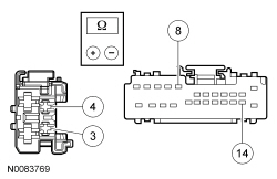 | Yes
INSTALL a new front seat track motor. REFER to Seat Track Motor — Front in this section. CLEAR the DTCs. REPEAT the self-test. DISCONNECT the battery ground cable. CONNECT driver seat side air bag C367 and driver seat safety belt buckle C3065. REPOWER the SRS . REFER to Section 501-20B . No REPAIR the circuit(s). CLEAR the DTCs. REPEAT the self-test. DISCONNECT the battery ground cable. CONNECT driver seat side air bag C367 and driver seat safety belt buckle C3065. REPOWER the SRS . REFER to Section 501-20B . | |||||||||
| K20 CHECK THE RECLINER MOTOR SENSOR CIRCUITS FOR A SHORT TO VOLTAGE | ||||||||||
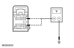 | Yes
REPAIR the circuit(s). CLEAR the DTCs. REPEAT the self-test. DISCONNECT the battery ground cable. CONNECT driver seat side air bag C367 and driver seat safety belt buckle C3065. REPOWER the SRS . REFER to Section 501-20B . No GO to K21 . | |||||||||
| K21 CHECK THE RECLINER MOTOR SENSOR CIRCUITS FOR A SHORT TO GROUND | ||||||||||
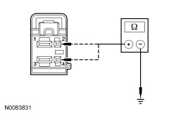 | Yes
GO to K22 . No REPAIR the circuit(s). CLEAR the DTCs. REPEAT the self-test. DISCONNECT the battery ground cable. CONNECT driver seat side air bag C367 and driver seat safety belt buckle C3065. REPOWER the SRS . REFER to Section 501-20B . | |||||||||
| K22 CHECK THE RECLINER MOTOR SENSOR CIRCUITS FOR AN OPEN | ||||||||||
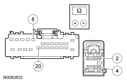 | Yes
INSTALL a new driver seat recliner motor. CLEAR the DTCs. REPEAT the self-test. DISCONNECT the battery ground cable. CONNECT driver seat side air bag C367 and driver seat safety belt buckle C3065. REPOWER the SRS . REFER to Section 501-20B . No REPAIR the circuit(s). CLEAR the DTCs. REPEAT the self-test. DISCONNECT the battery ground cable. CONNECT driver seat side air bag C367 and driver seat safety belt buckle C3065. REPOWER the SRS . REFER to Section 501-20B . |
Pinpoint Test L: Easy Exit/Easy Entry is Inoperative/Does Not Operate Correctly
The Driver Seat Module (DSM) receives a key out command over the Medium Speed Controller Area Network (MS-CAN) communication network and powers the driver seat rearward about 51 mm (2 in).
NOTE: Verify good battery condition before diagnosing the memory seat system. Poor battery condition may interfere with memory seat operation, even if vehicle starting is possible.
NOTE: The transmission gear selector must be in PARK and either the key removed (without Intelligent Access) or the ignition OFF (with Intelligent Access) for the easy entry/exit feature to function.
NOTE: If a new DSM is installed, the driver seat must be operated in all directions through the full range of travel to avoid a premature stopping point occurrence after the vehicle is returned to the customer.
NOTE: Make sure all memory seat DTC and symptom based faults are corrected before proceeding with easy entry/exit diagnosis. Verify the PID(s) states agree with the ignition and transmission gear selector in all positions before proceeding with easy entry/exit diagnosis.
| Test Step | Result / Action to Take |
|---|---|
| L1 CHECK FOR EASY ENTRY FEATURE ENABLE AND DRIVER POWER SEAT OPERATION | |
| Yes
RE-POSITION the seat at least 51 mm (2 in) from its rear stopping point and GO to L2 . No If disabled, ENABLE the easy entry/exit feature. TEST the system for normal operation. If OK, INSTRUCT the customer on correct feature operation. If the seat does not move horizontally using the seat control switch, GO to Pinpoint Test K . |
| L2 CHECK THE DSM FOR DTCs | |
| Yes
REFER to the Driver Seat Module (DSM) DTC Chart. No GO to L3 . |
| L3 CHECK THE TRANSMISSION RANGE (TR) PID | |
| Yes
GO to L4 . No To diagnose a transmission gear selector status concern, REFER to Section 307-01 . |
| L4 CHECK THE DSM FOR CORRECT IGNITION SWITCH POSITION (IGN_SW) PID STATES | |
| Yes
INSTALL a new DSM . REFER to Driver Seat Module (DSM) in this section. CLEAR the DTCs. REPEAT the self-test. No To diagnose the key-in-ignition warning switch fault, REFER to Section 413-01 . |
Pinpoint Test N: The Heated Seat is Inoperative/Does Not Operate Correctly — Driver
Refer to Wiring Diagrams Cell 119 , Climate Controlled Seats for schematic and connector information.
The driver and passenger heated seat control buttons and indicators are located on the touchscreen interface ( FDIM ). The FDIM is mounted directly to the APIM . The heated seat system functions independently of the vehicle's climate control system. Each time the heated seat button is pressed, the APIM sends the request to the FCIM using the I-CAN . The FCIM sends the message to the IPC using the I-CAN . The IPC sends the request message to the BCM over the HS-CAN . Finally, the BCM sends the request to the HVAC module which decreases one setting (the sequence is high, low, off, high, etc.).
When activated, the HVAC module supplies voltage to the selected seat's heater circuit. Each seat's cushion heater mat and backrest heater mat is connected in a series circuit to the HVAC module and powered by the output circuit for that seat. The HVAC module monitors inputs from a temperature sensor located in each seat's cushion heater mat, and maintains seat temperature by cycling the heater circuits on/off. The heated seat remains ON until the heated seat switch button is pressed to cycle the HVAC module OFF or the ignition is set to OFF.
If a fault is detected by the HVAC module, the module stops supplying voltage to that individual left or right seat that the fault was detected on until the ignition is turned OFF and then ON.
| DTC Description | Fault Trigger Conditions |
|---|---|
| B1034:11 — Left Front Seat Heater Element: Circuit Short To Ground | Sets when the HVAC module senses the left front heater element current draw has exceeded a specified threshold. When this DTC sets, the HVAC module disables the circuit until the ignition is cycled. |
| B1034:13 — Left Front Seat Heater Element: Circuit Open | Sets when the HVAC module senses the left front heater element current draw is less than a specified threshold. When this DTC sets, the HVAC module disables the circuit until the ignition is cycled. |
| B1038:11 — Left Front Seat Heater Sensor: Circuit Short To Ground | Sets when the HVAC module senses the left front heater sensor voltage is out-of-range low. When this DTC sets, the HVAC module disables the circuit until the ignition is cycled. |
| B1038:12 — Left Front Seat Heater Sensor: Circuit Short To Battery | Sets when the HVAC module senses the left front heater sensor voltage is out-of-range high. When this DTC sets, the HVAC module disables the circuit until the ignition is cycled. |
NOTE: The air bag warning indicator illuminates when the correct Restraints Control Module (RCM) fuse is removed and the ignition switch is on.
NOTE: The Supplemental Restraint System (SRS) must be fully operational and free of faults before releasing the vehicle to the customer.
| Test Step | Result / Action to Take |
|---|---|
| N1 CHECK THE HVAC MODULE DRIVER HEATED SEAT POWER FEED FOR VOLTAGE | |
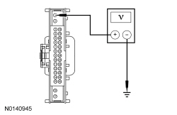 | Yes
GO to N2 . No VERIFY BJB fuse 29 (20A) is OK. If the fuse is OK, REPAIR the circuit. If not OK, REFER to the Wiring Diagrams manual to identify the possible causes of the circuit short. TEST the system for normal operation. |
| N2 CHECK THE HVAC MODULE DTCs | |
| Yes
For DTCs B1034:11 or B1034:13, GO to N4 . For DTCs B1038:11 or B1038:12, GO to N5 . For any other HVAC module DTCs, REFER to the HVAC Module DTC Chart in this section. No GO to N3 . |
| N3 CHECK THE TOUCHSCREEN CONTROLS OPERATION | |
| Yes
GO to N13 . No REFER to Section 415-00B or Section 415-00C to diagnose the inoperative touchscreen. |
| N4 CHECK THE HEATER ELEMENT POWER CIRCUIT FOR AN OPEN OR SHORT TO GROUND | |
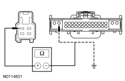 | Yes
GO to N8 . No REPAIR the circuit. TEST the system for normal operation. DISCONNECT the battery ground cable. CONNECT driver seat side air bag C367 and driver seat safety belt buckle C3065. REPOWER the SRS . REFER to Section 501-20B . |
| N5 CHECK THE HEATED SEAT TEMPERATURE SENSOR CIRCUIT FOR AN OPEN OR SHORT TO GROUND | |
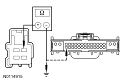 | Yes
GO to N6 . No REPAIR the circuit. TEST the system for normal operation. DISCONNECT the battery ground cable. CONNECT driver seat side air bag C367 and driver seat safety belt buckle C3065. REPOWER the SRS . REFER to Section 501-20B . |
| N6 CHECK THE HEATED SEAT TEMPERATURE SENSOR RETURN CIRCUIT FOR AN OPEN OR SHORT TO GROUND | |
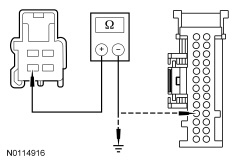 | Yes
GO to N7 . No REPAIR the circuit. TEST the system for normal operation. DISCONNECT the battery ground cable. CONNECT driver seat side air bag C367 and driver seat safety belt buckle C3065. REPOWER the SRS . REFER to Section 501-20B . |
| N7 CHECK THE HEATED SEAT TEMPERATURE SENSOR CIRCUIT FOR A SHORT TO VOLTAGE | |
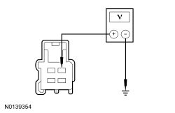 | Yes
REPAIR the circuit. TEST the system for normal operation. DISCONNECT the battery ground cable. CONNECT driver seat side air bag C367 and driver seat safety belt buckle C3065. REPOWER the SRS . REFER to Section 501-20B . No GO to N12 . |
| N8 CHECK THE HEATER ELEMENT GROUND CIRCUIT FOR AN OPEN | |
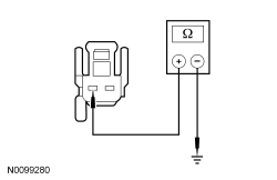 | Yes
GO to N9 . No REPAIR the circuit. TEST the system for normal operation. DISCONNECT the battery ground cable. CONNECT driver seat side air bag C367 and driver seat safety belt buckle C3065. REPOWER the SRS . REFER to Section 501-20B . |
| N9 CHECK CUSHION HEATED SEAT MAT FOR AN OPEN OR SHORT TO GROUND | |
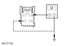 | Yes
GO to N10 . No INSTALL a new driver seat cushion heater mat. REFER to Seat Cushion Heater Mat — Front in this section. TEST the system for normal operation. DISCONNECT the battery ground cable. CONNECT driver seat side air bag C367 and driver seat safety belt buckle C3065. REPOWER the SRS . REFER to Section 501-20B . |
| N10 CHECK THE BACKREST HEATED SEAT MAT FOR AN OPEN OR SHORT TO GROUND | |
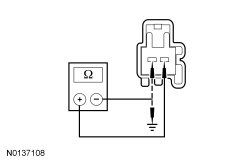 | Yes
GO to N11 . No INSTALL a new driver front seat backrest heater mat. REFER to Seat Backrest Heater Mat — Front in this section. TEST the system for normal operation. DISCONNECT the battery ground cable. CONNECT driver seat side air bag C367 and driver seat safety belt buckle C3065. REPOWER the SRS . REFER to Section 501-20B . |
| N11 CHECK THE CIRCUIT BETWEEN THE CUSHION HEATER MAT AND BACKREST HEATER MAT FOR AN OPEN AND SHORT TO GROUND | |
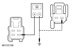 | Yes
GO to N13 . No REPAIR the circuit. TEST the system for normal operation. DISCONNECT the battery ground cable. CONNECT driver seat side air bag C367 and driver seat safety belt buckle C3065. REPOWER the SRS . REFER to Section 501-20B . |
| N12 CHECK THE HEATED SEAT TEMPERATURE SENSOR FOR AN OPEN OR SHORT TO GROUND | |
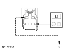 | Yes
GO to N13 . No INSTALL a new driver seat cushion heater mat. REFER to Seat Cushion Heater Mat — Front in this section. TEST the system for normal operation. DISCONNECT the battery ground cable. CONNECT driver seat side air bag C367 and driver seat safety belt buckle C3065. REPOWER the SRS . REFER to Section 501-20B . |
| N13 CHECK FOR CORRECT HVAC MODULE OPERATION | |
| Yes
CHECK OASIS for any applicable TSBs . If a TSB exists for this concern, DISCONTINUE this test and FOLLOW TSB instructions. If no TSB addresses this concern, INSTALL a new HVAC module. REFER to Section 412-01 . TEST the system for normal operation. If the SRS was previously depowered, DISCONNECT the battery ground cable. CONNECT driver seat side air bag C367 and driver seat safety belt buckle C3065. REPOWER the SRS . REFER to Section 501-20B . No The system is operating correctly at this time. The concern may have been caused by a loose or corroded connector. ADDRESS the root cause of any connector or pin issues. If the SRS was previously depowered, DISCONNECT the battery ground cable. CONNECT driver seat side air bag C367 and driver seat safety belt buckle C3065. REPOWER the SRS . REFER to Section 501-20B . |
Pinpoint Test O: The Heated Seat is Inoperative/Does Not Operate Correctly — Front Passenger
Refer to Wiring Diagrams Cell 119 , Climate Controlled Seats for schematic and connector information.
The driver and passenger heated seat control buttons and indicators are located on the touchscreen interface ( FDIM ). The FDIM is mounted directly to the APIM . The heated seat system functions independently of the vehicle's climate control system. Each time the heated seat button is pressed, the APIM sends the request to the FCIM using the I-CAN . The FCIM sends the message to the IPC using the I-CAN . The IPC sends the request message to the BCM over the HS-CAN . Finally, the BCM sends the request to the HVAC module which decreases one setting (the sequence is high, low, off, high, etc.).
When activated, the HVAC module supplies voltage to the selected seat's heater circuit. Each seat's cushion heater mat and backrest heater mat is connected in a series circuit to the HVAC module and powered by the output circuit for that seat. The HVAC module monitors inputs from a temperature sensor located in each seat's cushion heater mat, and maintains seat temperature by cycling the heater circuits on/off. The heated seat remains ON until the heated seat switch button is pressed to cycle the HVAC module OFF or the ignition is set to OFF.
If a fault is detected by the HVAC module, the module stops supplying voltage to that individual left or right seat that the fault was detected on until the ignition is turned OFF and then ON.
| DTC Description | Fault Trigger Conditions |
|---|---|
| B1036:11 — Right Front Seat Heater Element: Circuit Short To Ground | Sets when the HVAC module senses the right front heater element current draw has exceeded a specified threshold. When this DTC sets, the HVAC module disables the circuit until the ignition is cycled. |
| B1036:13 — Right Front Seat Heater Element: Circuit Open | Sets when the HVAC module senses the right front heater element current draw is less than a specified threshold. When this DTC sets, the HVAC module disables the circuit until the ignition is cycled. |
| B103A:11 — Right Front Seat Heater Sensor: Circuit Short To Ground | Sets when the HVAC module senses the right front heater sensor voltage is out-of-range low. When this DTC sets, the HVAC module disables the circuit until the ignition is cycled. |
| B103A:12 — Right Front Seat Heater Sensor: Circuit Short To Battery | Sets when the HVAC module senses the right front heater sensor voltage is out-of-range high. When this DTC sets, the HVAC module disables the circuit until the ignition is cycled. |
NOTE: The air bag warning indicator illuminates when the correct Restraints Control Module (RCM) fuse is removed and the ignition switch is on.
NOTE: The Supplemental Restraint System (SRS) must be fully operational and free of faults before releasing the vehicle to the customer.
| Test Step | Result / Action to Take |
|---|---|
| O1 CHECK THE HVAC MODULE DRIVER HEATED SEAT POWER FEED FOR VOLTAGE | |
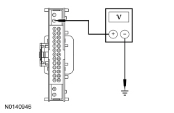 | Yes
GO to O2 . No VERIFY BJB fuse 29 (20A) is OK. If the fuse is OK, REPAIR the circuit. If not OK, REFER to the Wiring Diagrams manual to identify the possible causes of the circuit short. TEST the system for normal operation. |
| O2 CHECK THE HVAC MODULE DTCs | |
| Yes
For DTCs B10364:11 or B1036:13, GO to O4 . For DTCs B103A:11 or B103A:12, GO to O5 . For any other HVAC module DTCs, REFER to the HVAC Module DTC Chart in this section. No GO to O3 . |
| O3 CHECK THE TOUCHSCREEN CONTROLS OPERATION | |
| Yes
GO to O13 . No REFER to Section 415-00B or Section 415-00C to diagnose the inoperative touchscreen. |
| O4 CHECK THE HEATER ELEMENT POWER CIRCUIT FOR AN OPEN OR SHORT TO GROUND | |
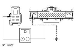 | Yes
GO to O8 . No REPAIR the circuit. TEST the system for normal operation. DISCONNECT the battery ground cable. CONNECT passenger seat side air bag C337 and passenger safety belt buckle C3066. REPOWER the SRS . REFER to Section 501-20B . |
| O5 CHECK THE HEATED SEAT TEMPERATURE SENSOR CIRCUIT FOR AN OPEN OR SHORT TO GROUND | |
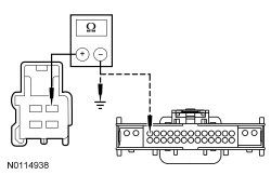 | Yes
GO to O6 . No REPAIR the circuit. TEST the system for normal operation. DISCONNECT the battery ground cable. CONNECT passenger seat side air bag C337 and passenger safety belt buckle C3066. REPOWER the SRS . REFER to Section 501-20B . |
| O6 CHECK THE HEATED SEAT TEMPERATURE SENSOR RETURN CIRCUIT FOR AN OPEN OR SHORT TO GROUND | |
 | Yes
GO to O7 . No REPAIR the circuit. TEST the system for normal operation. DISCONNECT the battery ground cable. CONNECT passenger seat side air bag C337 and passenger safety belt buckle C3066. REPOWER the SRS . REFER to Section 501-20B . |
| O7 CHECK THE HEATED SEAT TEMPERATURE SENSOR CIRCUIT FOR A SHORT TO VOLTAGE | |
 | Yes
REPAIR the circuit. TEST the system for normal operation. DISCONNECT the battery ground cable. CONNECT passenger seat side air bag C337 and passenger safety belt buckle C3066. REPOWER the SRS . REFER to Section 501-20B . No GO to O12 . |
| O8 CHECK THE HEATER ELEMENT GROUND CIRCUIT FOR AN OPEN | |
 | Yes
GO to O9 . No REPAIR the circuit. TEST the system for normal operation. DISCONNECT the battery ground cable. CONNECT passenger seat side air bag C337 and passenger safety belt buckle C3066. REPOWER the SRS . REFER to Section 501-20B . |
| O9 CHECK CUSHION HEATED SEAT MAT FOR AN OPEN OR SHORT TO GROUND | |
 | Yes
GO to O10 . No INSTALL a new passenger seat cushion heater mat. REFER to Seat Cushion Heater Mat — Front in this section. TEST the system for normal operation. DISCONNECT the battery ground cable. CONNECT passenger seat side air bag C337 and passenger safety belt buckle C3066. REPOWER the SRS . REFER to Section 501-20B . |
| O10 CHECK THE BACKREST HEATED SEAT MAT FOR AN OPEN OR SHORT TO GROUND | |
 | Yes
GO to O11 . No INSTALL a new passenger front seat backrest heater mat. REFER to Seat Backrest Heater Mat — Front in this section. TEST the system for normal operation. DISCONNECT the battery ground cable. CONNECT passenger seat side air bag C337 and passenger safety belt buckle C3066. REPOWER the SRS . REFER to Section 501-20B . |
| O11 CHECK THE CIRCUIT BETWEEN THE CUSHION HEATER MAT AND BACKREST HEATER MAT FOR AN OPEN AND SHORT TO GROUND | |
 | Yes
GO to O13 . No REPAIR the circuit. TEST the system for normal operation. DISCONNECT the battery ground cable. CONNECT passenger seat side air bag C337 and passenger safety belt buckle C3066. REPOWER the SRS . REFER to Section 501-20B . |
| O12 CHECK THE HEATED SEAT TEMPERATURE SENSOR FOR AN OPEN OR SHORT TO GROUND | |
 | Yes
GO to O13 . No INSTALL a new passenger seat cushion heater mat. REFER to Seat Cushion Heater Mat — Front in this section. TEST the system for normal operation. DISCONNECT the battery ground cable. CONNECT passenger seat side air bag C337 and passenger safety belt buckle C3066. REPOWER the SRS . REFER to Section 501-20B . |
| O13 CHECK FOR CORRECT HVAC MODULE OPERATION | |
| Yes
CHECK OASIS for any applicable TSBs . If a TSB exists for this concern, DISCONTINUE this test and FOLLOW TSB instructions. If no TSB addresses this concern, INSTALL a new HVAC module. REFER to Section 412-01 . TEST the system for normal operation. If the SRS was previously depowered, DISCONNECT the battery ground cable. CONNECT passenger seat side air bag C337 and passenger safety belt buckle C3066. REPOWER the SRS . REFER to Section 501-20B . No The system is operating correctly at this time. The concern may have been caused by a loose or corroded connector. ADDRESS the root cause of any connector or pin issues. If the SRS was previously depowered, DISCONNECT the battery ground cable. CONNECT passenger seat side air bag C337 and passenger safety belt buckle C3066. REPOWER the SRS . REFER to Section 501-20B . |
Pinpoint Test R: The Power Seat is Inoperative/Does Not Operate Correctly — Second Row, Power-Fold
Refer to Wiring Diagrams Cell 120 , Power Seats for schematic and connector information.
Each second row power-fold seat receives battery voltage from the Body Control Module (BCM) at all times. The power-fold seat motors contain internal switching that operate the motor until it moves to the reset position and turns off. The demand lighting/battery saver voltage output circuit from the BCM provides the control signal voltage to each seat control switch. The seat control switches have momentary contacts. When the seat control switch is pressed and held for at least one second, switched voltage is supplied to the power-fold seat motor control circuits to initiate a pull and release cycle. The power-fold seat motor retracts a release cable connected to the same mechanical release lever in the seat latch mechanism as the manual release pull strap. When the power-fold seat motor is cycled, the pull strap retraction and release/reset is noticeable.
NOTE: Make sure the second row power-fold seats manually release and latch before troubleshooting the electrical system.
| Test Step | Result / Action to Take |
|---|---|
| R1 CHECK MANUAL RELEASE OPERATION OF THE SEAT BACKREST | |
NOTE: Before performing this step, make sure there are no aftermarket accessories or foreign objects that may affect the seat not to fold properly. | Yes
GO to R2 . No If the backrest does not unlatch, DISASSEMBLE the seat as necessary to CHECK the cables and cable mounting for disconnection. CHECK latch release mechanism and latch feet for binding or damage. REPAIR as needed. TEST the system for normal operation. If the backrest unlatches but does not fold forward onto the seat cushion properly, CHECK for aftermarket accessories or foreign objects that may be causing the binding condition. If OK, INSTALL a new seat recliner. REFER to Seat Recliner — Second Row, 40 Percent in this section. TEST the system for normal operation. |
| R2 CHECK MANUAL RELEASE OPERATION OF THE SEAT CUSHION WITH THE SEAT FULLY FORWARD | |
| Yes
GO to R3 . No If the seat cushion does not unlatch, DISASSEMBLE the seat as necessary to CHECK the cables and cable mounting for disconnection. CHECK latch release mechanism and latch feet for binding or damage. REPAIR as needed. TEST the system for normal operation. If the seat cushion unlatches but does not lift and fold forward to the E-Z entry position properly, GO to R4 . |
| R3 CHECK MANUAL RELEASE OPERATION OF THE SEAT CUSHION WITH THE SEAT FULLY REARWARD | |
| Yes
GO to R5 . No GO to R4 . |
| R4 NEUTRALIZE THE SEAT TRACK AND MOUNTING BRACKETS | |
| Yes
The system is operating correctly at this time. Concern was caused due to binding condition within the seat track assembly. No INSTALL a new gas assist strut. TEST the system for normal operation. If concern is still present, INSTALL a new seat track assembly. REFER to Seat Track — Second Row, 40 Percent in this section. TEST the system for normal operation. |
| R5 CHECK THE INTERIOR DEMAND LIGHTING/ BATTERY SAVER OPERATION | |
| Yes
GO to R6 . No REFER to Section 417-02 to diagnose the inoperative demand lighting/ battery saver concern. |
| R6 CHECK FOR VOLTAGE TO THE POWER-FOLD SEAT MOTORS | |
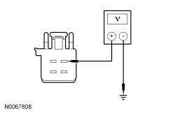 | Yes
GO to R7 . No VERIFY BCM fuse 2 (15A) is OK. If the fuse is OK, REPAIR the circuit. If not OK, REFER to the Wiring Diagrams manual to identify the possible causes of the circuit short. TEST the system for normal operation. If equipped with inflatable safety belts, GO to R13 . |
| R7 CHECK FOR AN OPEN GROUND CIRCUIT | |
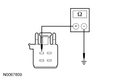 | Yes
GO to R8 . No REPAIR the circuit in question. TEST the system for normal operation. If equipped with inflatable safety belts, GO to R13 . |
| R8 CHECK FOR VOLTAGE FROM THE SEAT CONTROL SWITCH | |
NOTE: If the demand lighting/battery saver system has timed out, close and re-open any of the vehicle doors to activate the system before measuring the voltage. 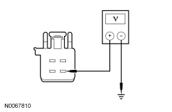 | Yes
INSTALL a new LH or RH power-fold seat motor. REFER to Power-Fold Seat Motor — Second Row, 40 Percent in this section. TEST the system for normal operation. If equipped with inflatable safety belts, GO to R13 . No GO to R9 . |
| R9 CHECK THE SEAT CONTROL SWITCH FOR VOLTAGE | |
NOTE: If the demand lighting/ battery saver system has timed out, close and re-open any of the vehicle doors to activate the system before measuring the voltage. 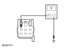 | Yes
GO to R10 . No REPAIR the circuit. If not OK, REFER to the Wiring Diagrams manual to identify the possible causes of the circuit short. TEST the system for normal operation. If equipped with inflatable safety belts, GO to R13 . |
| R10 CHECK THE SEAT CONTROL SWITCH | |
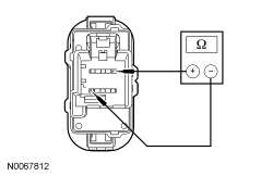 | Yes
GO to R11 . No INSTALL a new LH or RH seat control switch. REFER to Seat Control Switch — Second Row, Power-Fold . TEST the system for normal operation. If equipped with inflatable safety belts, GO to R13 . |
| R11 CHECK THE POWER-FOLD SEAT MOTOR CIRCUITS FOR A SHORT TO VOLTAGE | |
NOTE: If the demand lighting/ battery saver system has timed out, close and re-open any of the vehicle doors to activate the system before measuring the voltage. 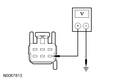 | Yes
REPAIR the affected circuit. TEST the system for normal operation. If equipped with inflatable safety belts, GO to R13 . No GO to R12 . |
| R12 CHECK THE POWER-FOLD SEAT MOTOR CIRCUITS FOR AN OPEN | |
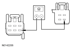 | Yes
The system checks OK at this time. CHECK all connections are clean and fully connected. TEST the system for normal operation. REPEAT the pinpoint test if the seat does not release. If equipped with inflatable safety belts, GO to R13 . No REPAIR the circuit in question. TEST the system for normal operation. If equipped with inflatable safety belts, GO to R13 . |
| R13 CHECK FOR SRS DTCs | |
| Yes
REFER to Section 501-20B for pinpoint test direction. No The repair is complete. RETURN the vehicle to the customer. |
Pinpoint Test S: The Power Seat is Inoperative — Second Row, Power-Fold Seat Does Not Latch to the Floor
Refer to Wiring Diagrams Cell 120 , Power Seats for schematic and connector information.
Each second row power-fold seat receives battery voltage from the Body Control Module (BCM) at all times. The power-fold seat motors contain internal switching that operate the motor until it moves to the reset position and turns off. The demand lighting/ battery saver voltage output circuit from the BCM provides the control signal voltage to each seat control switch. The seat control switches are momentary contact switches when pressed and held for at least one second supply switched voltage to the power-fold seat motor control circuit to initiate a pull and release cycle. The power-fold seat motor retracts a release cable connected to the same mechanical release lever in the seat latch mechanism as the manual release pull strap. When the power-fold seat motor is cycled, the pull strap retraction and release/reset is noticeable.
| Test Step | Result / Action to Take |
|---|---|
| S1 CHECK THE INTERIOR DEMAND LIGHTING/ BATTERY SAVER OPERATION | |
| Yes
If the opposite seat does not operate from the seat control switch, GO to S3 . Otherwise, GO to S2 . No REFER to Section 417-02 to diagnose the inoperative demand lighting/ battery saver concern. |
| S2 CHECK THE SEAT LATCH FEET FOR MANUAL MECHANICAL OPERATION | |
| Yes
DISASSEMBLE the seat as necessary to REPAIR the latch(es), cable(s) or release pull strap. TEST the system for normal operation. If the cause is not found, DETACH the power-fold release cable from the latch and RETEST the mechanical latch operation. If the latch(es) continue to be inoperative with the cable detached, INSTALL a new latch mechanism or latch foot/feet as needed. REASSEMBLE the seat and TEST for normal operation. If the seat latches and manually releases correctly with the power-fold seat motor cable disconnected, GO to S3 . No GO to S3 . |
| S3 CHECK FOR VOLTAGE TO THE POWER-FOLD SEAT MOTOR | |
 | Yes
GO to S4 . No VERIFY BCM fuse 2 (15A) is OK. If the fuse is OK, REPAIR the circuit. If not OK, REFER to the Wiring Diagrams manual to identify the possible causes of the circuit short. TEST the system for normal operation. If equipped with inflatable safety belts, GO to S5 . |
| S4 CHECK FOR AN OPEN GROUND CIRCUIT | |
 | Yes
INSTALL a new LH or RH power-fold seat motor. REFER to Power-Fold Seat Motor — Second Row, 40 Percent in this section. TEST the system for normal operation. If equipped with inflatable safety belts, GO to S5 . No REPAIR the circuit. TEST the system for normal operation. If equipped with inflatable safety belts, GO to S5 . |
| S5 CHECK FOR SRS DTCs | |
| Yes
REFER to Section 501-20B for pinpoint test direction. No The repair is complete. RETURN the vehicle to the customer. |
Pinpoint Test T: The Heated Seats are Inoperative — Rear
Refer to Wiring Diagrams Cell 119 , Climate Controlled Seats for schematic and connector information.
When ignition voltage is supplied and the driver or passenger heated seat button on the auxiliary climate control assembly is pressed, a momentary ground signal is sent to the heated seat module to command the system on or off. Upon receiving a signal, the heated seat module decreases one setting (the sequence is high, low, off, high). The heated seat module monitors temperature sensors contained within the cushion heater mats on the left and right rear seats. The temperature sensors share a common return circuit to the heated seat module. If the temperature sensor return circuit opens (resistance greater than 300,000 ohms), the heated seat module disables the outputs to both seats. The system remains disabled until the circuit is repaired and the heated seat module is reset by cycling the ignition OFF and ON.
| Test Step | Result / Action to Take |
|---|---|
| T1 CHECK THE VOLTAGE TO THE REAR HEATED SEAT MODULE | |
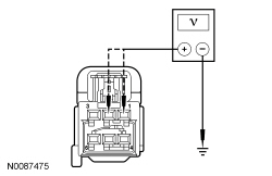 | Yes
GO to T2 . No VERIFY BJB fuse 30 (20A) and BCM fuse 34 (10A). If OK, REPAIR the affected circuit. If not OK, REFER to the Wiring Diagrams manual to identify the possible causes of the circuit short. TEST the system for normal operation. If equipped with inflatable safety belts, GO to T7 . |
| T2 CHECK THE HEATED SEAT MODULE GROUND CIRCUIT FOR AN OPEN | |
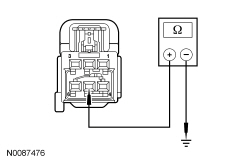 | Yes
GO to T3 . No REPAIR the circuit. TEST the system for normal operation. If equipped with inflatable safety belts, GO to T7 . |
| T3 CHECK TEMPERATURE SENSOR CIRCUITS FOR A SHORT TO VOLTAGE | |
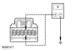 | Yes
REPAIR the affected circuit. TEST the system for normal operation. If equipped with inflatable safety belts, GO to T7 . No GO to T4 . |
| T4 CHECK TEMPERATURE SENSOR CIRCUITS FOR A SHORT TO GROUND | |
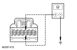 | Yes
GO to T5 . No REPAIR the affected circuit. TEST the system for normal operation. If equipped with inflatable safety belts, GO to T7 . |
| T5 CHECK THE TEMPERATURE SENSOR RETURN CIRCUIT FOR AN OPEN | |
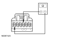 | Yes
GO to T6 . No REPAIR circuit RHS41 (GN/BN). TEST the system for normal operation. If equipped with inflatable safety belts, GO to T7 . |
| T6 CHECK THE AUXILIARY CLIMATE CONTROL ASSEMBLY OUTPUT | |
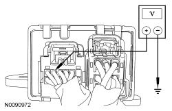 | Yes
INSTALL a new heated seat module. REFER to Heated Seat Module — Rear in this section. TEST the system for normal operation. If equipped with inflatable safety belts, GO to T7 . No If the voltage is greater than 11 volts but did not drop when the LH rear heated seat button was pressed, INSTALL a new rear auxiliary climate control assembly. REFER to Section 412-02 . If the voltage is less than 11 volts, INSTALL a new heated seat module. REFER to Heated Seat Module — Rear in this section. TEST the system for normal operation. If equipped with inflatable safety belts, GO to T7 . |
| T7 CHECK FOR SRS DTCs | |
| Yes
REFER to Section 501-20B for pinpoint test direction. No The repair is complete. RETURN the vehicle to the customer. |
Pinpoint Test U: The Heated Seat is Inoperative/Does Not Operate Correctly — Left Rear
Refer to Wiring Diagrams Cell 119 , Climate Controlled Seats for schematic and connector information.
The heated seat module receives constant battery voltage. When the ignition is on and the LH rear heated seat button on the auxiliary climate control assembly is pressed, a momentary ground signal is sent to the heated seat module on command circuit to turn the system on or off. Upon receiving a signal, the heated seat module decreases one setting (the sequence is high, low, off, high). The heated seat module supplies voltage to the cushion and backrest heater mats. The cushion and backrest heater mats are connected in series and operate together. Temperature is maintained by a temperature sensor contained within the cushion heater mat. The heated seat module supplies a reference voltage to the temperature sensor and monitors the signal to control current flow to the heater mats.
| Test Step | Result / Action to Take |
|---|---|
| U1 CHECK THE VOLTAGE TO THE REAR HEATED SEAT MODULE | |
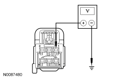 | Yes
GO to U2 . No REPAIR the circuit. TEST the system for normal operation. If equipped with inflatable safety belts, GO to U15 . |
| U2 CHECK LEFT REAR HEATER MATS RESISTANCE AND HEATER CIRCUITS FOR AN OPEN | |
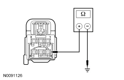 | Yes
GO to U7 . No GO to U3 . |
| U3 CHECK LEFT REAR SEAT CUSHION HEATER CIRCUIT FOR AN OPEN AND SHORT TO GROUND | |
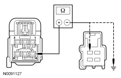 | Yes
GO to U4 . No REPAIR the circuit. TEST the system for normal operation. If equipped with inflatable safety belts, GO to U15 . |
| U4 CHECK LEFT REAR HEATER MATS GROUND CIRCUIT FOR AN OPEN | |
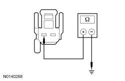 | Yes
GO to U5 . No REPAIR the circuit. TEST the system for normal operation. If equipped with inflatable safety belts, GO to U15 . |
| U5 CHECK LEFT REAR CUSHION HEATER MAT FOR AN OPEN | |
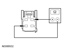 | Yes
GO to U6 . No INSTALL a new left rear cushion heater mat. REFER to Seat Cushion Heater Mat — Second Row, 40 Percent in this section. TEST the system for normal operation. If equipped with inflatable safety belts, GO to U15 . |
| U6 CHECK LEFT REAR BACKREST HEATER MAT FOR AN OPEN | |
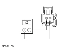 | Yes
REPAIR circuit CHS40 (GY/VT). TEST the system for normal operation. If equipped with inflatable safety belts, GO to U15 . No INSTALL a new rear seat backrest heater mat. REFER to Seat Backrest Heater Mat — Second Row, 40 Percent in this section. TEST the system for normal operation. If equipped with inflatable safety belts, GO to U15 . |
| U7 CHECK TEMPERATURE SENSOR CIRCUIT FOR A SHORT TO VOLTAGE | |
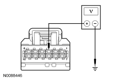 | Yes
REPAIR the circuit. TEST the system for normal operation. If equipped with inflatable safety belts, GO to U15 . No GO to U8 . |
| U8 CHECK HEATED SEAT TEMPERATURE SENSOR CIRCUITS FOR AN OPEN AND SHORT TO GROUND | |
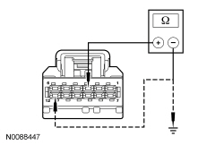 | Yes
GO to U11 . No GO to U9 . |
| U9 CHECK HEATED SEAT TEMPERATURE SENSOR CIRCUIT FOR AN OPEN AND SHORT TO GROUND | |
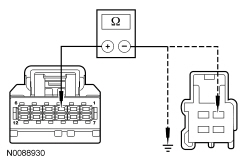 | Yes
GO to U10 . No REPAIR the circuit. TEST the system for normal operation. If equipped with inflatable safety belts, GO to U15 . |
| U10 CHECK TEMPERATURE SENSOR FOR AN OPEN | |
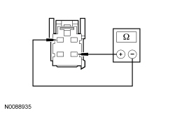 | Yes
REPAIR circuit RHS41 (GN/BN). TEST the system for normal operation. If equipped with inflatable safety belts, GO to U15 . No INSTALL a new rear seat cushion heater mat. REFER to Seat Cushion Heater Mat — Second Row, 40 Percent in this section. TEST the system for normal operation. If equipped with inflatable safety belts, GO to U15 . |
| U11 CHECK HEATED SEAT MODULE COMMAND CIRCUIT FOR SHORT TO VOLTAGE | |
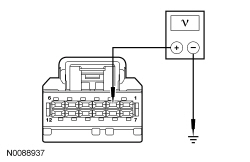 | Yes
REPAIR the circuit. TEST the system for normal operation. If equipped with inflatable safety belts, GO to U15 . No GO to U12 . |
| U12 CHECK HEATED SEAT MODULE COMMAND CIRCUIT FOR A SHORT TO GROUND | |
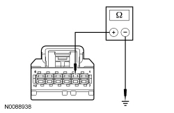 | Yes
GO to U13 . No REPAIR the circuit. TEST the system for normal operation. If equipped with inflatable safety belts, GO to U15 . |
| U13 CHECK HEATED SEAT MODULE COMMAND CIRCUIT FOR AN OPEN | |
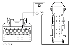 | Yes
GO to U14 . No REPAIR the circuit. TEST the system for normal operation. If equipped with inflatable safety belts, GO to U15 . |
| U14 CHECK THE AUXILIARY CLIMATE CONTROL ASSEMBLY OUTPUT | |
 | Yes
INSTALL a new heated seat module. REFER to Heated Seat Module — Rear in this section. TEST the system for normal operation. If equipped with inflatable safety belts, GO to U15 . No If the voltage is greater than 11 volts but did not drop when the driver heated seat button was pressed, INSTALL a new auxiliary climate control assembly. REFER to Section 412-02 . If the voltage is less than 11 volts, INSTALL a new heated seat module. REFER to Heated Seat Module — Rear in this section. TEST the system for normal operation. If equipped with inflatable safety belts, GO to U15 . |
| U15 CHECK FOR SRS DTCs | |
| Yes
REFER to Section 501-20B for pinpoint test direction. No The repair is complete. RETURN the vehicle to the customer. |
Pinpoint Test V: The Heated Seat is Inoperative/Does Not Operate Correctly — Right Rear
Refer to Wiring Diagrams Cell 119 , Climate Controlled Seats for schematic and connector information.
When the ignition is on and the driver heated seat button on the auxiliary climate control assembly is pressed, a momentary ground signal is sent to the heated seat module on the command circuit to turn the system on or off. Upon receiving a signal, the heated seat module decreases one setting (the sequence is high, low, off, high). The heated seat module supplies voltage to the cushion and backrest heater mats. The cushion and backrest heater mats are connected in series and operate together. Temperature is maintained by a temperature sensor contained within the cushion heater mat. The heated seat module supplies a reference voltage to the temperature sensor and monitors the signal to control current flow to the heater mats.
| Test Step | Result / Action to Take |
|---|---|
| V1 CHECK THE VOLTAGE TO THE REAR HEATED SEAT MODULE | |
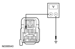 | Yes
GO to V2 . No REPAIR the circuit. TEST the system for normal operation. If equipped with inflatable safety belts, GO to V15 . |
| V2 CHECK RIGHT REAR HEATER MATS RESISTANCE AND HEATER CIRCUITS FOR AN OPEN | |
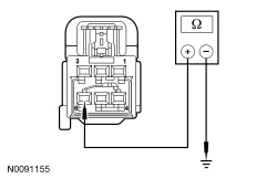 | Yes
GO to V7 . No GO to V3 . |
| V3 CHECK RIGHT REAR SEAT CUSHION HEATER CIRCUIT FOR AN OPEN AND SHORT TO GROUND | |
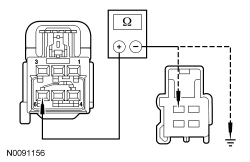 | Yes
GO to V4 . No REPAIR the circuit. TEST the system for normal operation. If equipped with inflatable safety belts, GO to V15 . |
| V4 CHECK RIGHT REAR HEATER MATS GROUND CIRCUIT FOR AN OPEN | |
 | Yes
GO to V5 . No REPAIR the circuit. TEST the system for normal operation. If equipped with inflatable safety belts, GO to V15 . |
| V5 CHECK RIGHT REAR CUSHION HEATER MAT FOR AN OPEN | |
 | Yes
GO to V6 . No INSTALL a new right rear cushion heater mat. REFER to Seat Cushion Heater Mat — Second Row, 40 Percent in this section. TEST the system for normal operation. If equipped with inflatable safety belts, GO to V15 . |
| V6 CHECK RIGHT REAR BACKREST HEATER MAT FOR AN OPEN | |
 | Yes
REPAIR circuit CHS44 (GN/VT). TEST the system for normal operation. If equipped with inflatable safety belts, GO to V15 . No INSTALL a new rear seat backrest heater mat. REFER to Seat Backrest Heater Mat — Second Row, 40 Percent in this section. TEST the system for normal operation. If equipped with inflatable safety belts, GO to V15 . |
| V7 CHECK TEMPERATURE SENSOR CIRCUIT FOR A SHORT TO VOLTAGE | |
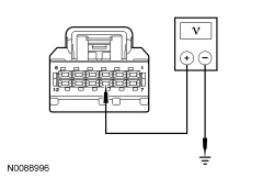 | Yes
REPAIR the circuit. TEST the system for normal operation. If equipped with inflatable safety belts, GO to V15 . No GO to V8 . |
| V8 CHECK HEATED SEAT TEMPERATURE SENSOR CIRCUITS FOR AN OPEN AND SHORT TO GROUND | |
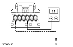 | Yes
GO to V11 . No GO to V9 . |
| V9 CHECK HEATED SEAT TEMPERATURE SENSOR CIRCUIT FOR AN OPEN AND SHORT TO GROUND | |
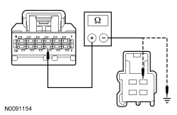 | Yes
GO to V10 . No REPAIR the circuit. TEST the system for normal operation. If equipped with inflatable safety belts, GO to V15 . |
| V10 CHECK THE TEMPERATURE SENSOR FOR AN OPEN | |
 | Yes
REPAIR ground circuit RHS41 (GN/BN). TEST the system for normal operation. If equipped with inflatable safety belts, GO to V15 . No INSTALL a new rear seat cushion heater mat. REFER to Seat Cushion Heater Mat — Second Row, 40 Percent in this section. TEST the system for normal operation. If equipped with inflatable safety belts, GO to V15 . |
| V11 CHECK HEATED SEAT MODULE COMMAND CIRCUIT FOR SHORT TO VOLTAGE | |
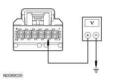 | Yes
REPAIR the circuit. TEST the system for normal operation. If equipped with inflatable safety belts, GO to V15 . No GO to V12 . |
| V12 CHECK HEATED SEAT MODULE COMMAND CIRCUIT FOR A SHORT TO GROUND | |
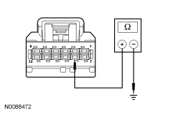 | Yes
GO to V13 . No REPAIR the circuit. TEST the system for normal operation. If equipped with inflatable safety belts, GO to V15 . |
| V13 CHECK HEATED SEAT MODULE COMMAND CIRCUIT FOR AN OPEN | |
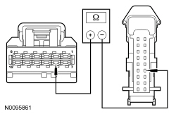 | Yes
GO to V14 . No REPAIR the circuit. TEST the system for normal operation. If equipped with inflatable safety belts, GO to V15 . |
| V14 CHECK THE AUXILIARY CLIMATE CONTROL ASSEMBLY OUTPUT | |
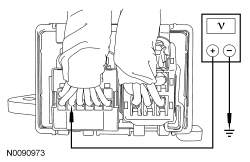 | Yes
INSTALL a new heated seat module. REFER to Heated Seat Module — Rear in this section. TEST the system for normal operation. If equipped with inflatable safety belts, GO to V15 . No If the voltage is greater than 11 volts but did not drop when the RH rear heated seat button was pressed, INSTALL a new auxiliary climate control assembly. REFER to Section 412-02 . If the voltage is less than 11 volts, INSTALL a new heated seat module. REFER to Heated Seat Module — Rear in this section. TEST the system for normal operation. If equipped with inflatable safety belts, GO to V15 . |
| V15 CHECK FOR SRS DTCs | |
| Yes
REFER to Section 501-20B for pinpoint test direction. No The repair is complete. RETURN the vehicle to the customer. |
Pinpoint Test W: The Heated Seat Does Not Operate Correctly — Left Rear Seat Does Heat but the Heated Seat Indicator Does Not Illuminate When Pressed
Refer to Wiring Diagrams Cell 119 , Climate Controlled Seats for schematic and connector information.
Upon receiving a pulsed ground from the auxiliary climate control assembly, the rear heated seat module decreases one setting (the sequence is high, low, off, high). There are 2 circuits between the rear heated seat module and auxiliary climate control assembly that control the indicator operation. When voltage is supplied to the auxiliary climate control assembly on either of these circuits the appropriate indicator illuminates. When a heated seat is set to high, both indicators on the heated seat control button illuminate. When a heated seat is set to low, only the lower indicator illuminates. When a heated seat is set to off, neither is illuminated.
| Test Step | Result / Action to Take |
|---|---|
| W1 CHECK THE INDICATOR CIRCUITS FOR A SHORT TO GROUND | |
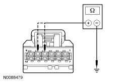 | Yes
GO to W2 . No REPAIR the affected circuit. TEST the system for normal operation. If equipped with inflatable safety belts, GO to W5 . |
| W2 CHECK THE INDICATOR CIRCUITS FOR AN OPEN | |
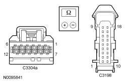 | Yes
GO to W3 . No REPAIR the affected circuit. TEST the system for normal operation. If equipped with inflatable safety belts, GO to W5 . |
| W3 CHECK THE HEATED SEAT HIGH INDICATOR | |
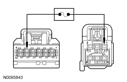 | Yes
GO to W4 . No INSTALL a new auxiliary climate control assembly. REFER to Section 412-02 . If equipped with inflatable safety belts, GO to W5 . |
| W4 CHECK THE HEATED SEAT LOW INDICATOR | |
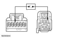 | Yes
INSTALL a new heated seat module. REFER to Heated Seat Module — Rear in this section. TEST the system for normal operation. If equipped with inflatable safety belts, GO to W5 . No INSTALL a new auxiliary climate control assembly. REFER to Section 412-02 . TEST the system for normal operation. If equipped with inflatable safety belts, GO to W5 . |
| W5 CHECK FOR SRS DTCs | |
| Yes
REFER to Section 501-20B for pinpoint test direction. No The repair is complete. RETURN the vehicle to the customer. |
Pinpoint Test X: The Heated Seat Does Not Operate Correctly — Right Rear Seat Does Heat but the Heated Seat Indicator Does Not Illuminate When Pressed
Refer to Wiring Diagrams Cell 119 , Climate Controlled Seats for schematic and connector information.
Upon receiving a pulsed ground from the auxiliary climate control assembly, the rear heated seat module decreases one setting (the sequence is high, low, off, high). There are 2 circuits between the rear heated seat module and auxiliary climate control assembly that control the indicator operation. When voltage is supplied to the auxiliary climate control assemblyon either of these circuits the appropriate indicator illuminates. When a heated seat is set to high, both indicators on the heated seat control button illuminate. When a heated seat is set to low, only the lower indicator illuminates. When a heated seat is set to off, neither is illuminated.
| Test Step | Result / Action to Take |
|---|---|
| X1 CHECK THE INDICATOR CIRCUITS FOR A SHORT TO GROUND | |
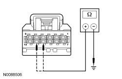 | Yes
GO to X2 . No REPAIR the affected circuit. TEST the system for normal operation. If equipped with inflatable safety belts, GO to X5 . |
| X2 CHECK THE INDICATOR CIRCUITS FOR AN OPEN | |
 | Yes
GO to X3 . No REPAIR the affected circuit. TEST the system for normal operation. If equipped with inflatable safety belts, GO to X5 . |
| X3 CHECK THE HEATED SEAT HIGH INDICATOR | |
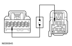 | Yes
GO to X4 . No INSTALL a new auxiliary climate control assembly. REFER to Section 412-02 . If equipped with inflatable safety belts, GO to X5 . |
| X4 CHECK THE HEATED SEAT LOW INDICATOR | |
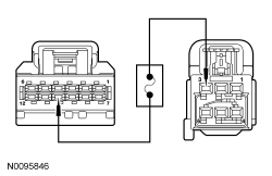 | Yes
INSTALL a new heated seat module. REFER to Heated Seat Module — Rear in this section. TEST the system for normal operation. If equipped with inflatable safety belts, GO to X5 . No INSTALL a new auxiliary climate control assembly. REFER to Section 412-02 . If equipped with inflatable safety belts, GO to X5 . |
| X5 CHECK FOR SRS DTCs | |
| Yes
REFER to Section 501-20B for pinpoint test direction. No The repair is complete. RETURN the vehicle to the customer. |
Pinpoint Test Y: The Heated Seat Does Not Operate Correctly — Left Rear Seat Does Heat but the Heated Seat Indicator is On All the Time
Refer to Wiring Diagrams Cell 119 , Climate Controlled Seats for schematic and connector information.
Pressing the left rear heated seat switch once in either the high or low mode commands on the left rear heated seat. Voltage is then supplied to the left rear heated seat switch from the heated seat module on one circuit for high heat mode or another for low heat mode to illuminate the switch indicator. Pressing the left rear heated seat switch again in the mode that is currently on sets the left rear heated seat to off and also turns that LED off.
| Test Step | Result / Action to Take |
|---|---|
| Y1 CHECK HEATED SEAT INDICATOR CIRCUITS FOR A SHORT TO VOLTAGE | |
| Yes
INSTALL a new heated seat module. REFER to Heated Seat Module — Rear in this section. TEST the system for normal operation. No REPAIR the affected circuit. TEST the system for normal operation. |
Pinpoint Test Z: The Heated Seat Does Not Operate Correctly — Right Rear Seat Does Heat but the Heated Seat Indicator is On All the Time
Refer to Wiring Diagrams Cell 119 , Climate Controlled Seats for schematic and connector information.
Pressing the right rear heated seat switch once in either the high or low mode commands on the right rear heated seat. Voltage is then supplied to the right rear heated seat switch from the heated seat module on one circuit for high heat mode or another for low heat mode to illuminate the switch indicator. Pressing the right rear heated seat switch again in the mode that is currently on sets the right rear heated seat to off and also turns that LED off.
| Test Step | Result / Action to Take |
|---|---|
| Z1 CHECK HEATED SEAT INDICATOR CIRCUITS FOR A SHORT TO VOLTAGE | |
| Yes
INSTALL a new heated seat module. REFER to Heated Seat Module — Rear in this section. TEST the system for normal operation. No REPAIR the affected circuit. TEST the system for normal operation. |
Pinpoint Test AA: The Seat Backrest Will Not Fold Upright — Second Row, 60 Percent
The seat recliner contains a safety mechanism to prevent the backrest from being raised upright until the seat latches are latched to the strikers on the floor. When the backrest is folded down, the safety mechanism is engaged by the cable attached to the outboard latch foot and outboard recliner. The safety mechanism is disengaged when the seat latch feet are completely locked around the strikers allowing the backrest to be raised upright.
The safety belt retractor in the backrest uses a stop button in the safety belt webbing to prevent the webbing from retracting too far into the retractor. If the web stop button is damaged or missing and the seat backrest is lowered, the safety belt webbing may retract farther than intended and may also prevent the backrest from being raised fully upright. A service kit is available for web stop button installation.
Pinpoint Test AB: The Seat Backrest Will Not Fold Down — Second Row, 60 Percent
Pulling the seat recliner handle releases the backrest for recline positions and to fold down. When the backrest is folded fully down, pulling the recliner handle again to the second stop position releases the seat latch feet from the strikers for the E-Z entry position. The inboard and outboard recliners operate in a synchronized manner and both lock the backrest when upright. The outboard recliner is released directly by the recliner lever while the inboard recliner is released by a cable attached to the recliner lever.
| Test Step | Result / Action to Take |
|---|---|
| AB1 CHECK FOR INTERMITTENT OPERATION OR BINDING RELEASE | |
NOTICE: The backrest must be folded flat before the floor latches can be released. Make sure there are no objects on the seat before lowering the backrest(s). Failure to follow this instruction may cause damage or incorrect operation of the seat. | Yes
INSTALL a new RH recliner (inboard). REFER to Seat Recliner — Inboard, Second Row, 60 Percent in this section. TEST the system for normal operation. No GO to AB2 . |
| AB2 CHECK THE LH RECLINER AND CABLES FOR DAMAGE | |
| Yes
INSTALL a new RH recliner (inboard). Do not re-use the original cable. REFER to Seat Recliner — Inboard, Second Row, 60 Percent in this section. TEST the system for normal operation. No REPAIR or INSTALL new components as needed. TEST the system for normal operation. |
Pinpoint Test AC: The Seat Backrest Will Not Fold Down/Fold Upright — Second Row, 40 Percent (RH or LH)
Pulling the seat recliner handle releases the backrest for recline positions and to fold down. When the backrest is folded fully down, pulling the recliner handle again to the second stop position releases the seat latch feet from the strikers for the E-Z entry position. The inboard and outboard recliners operate in a synchronized manner and both lock the backrest when upright. When folding the backrest down, the outboard recliner is released directly by the recliner lever while the inboard recliner is released by a cable attached to the outboard recliner. If the backrest is not folded all the way down, the seat does not release to the E-Z entry position.
The seat recliner contains a safety mechanism to prevent the backrest from being raised upright until the seat latches are latched to the strikers on the floor. When the backrest is folded down, the safety mechanism is engaged by the cable attached to the inboard latch foot and outboard recliner. The safety mechanism is disengaged when the seat latch feet are completely locked around the strikers allowing the backrest to be raised upright.
| Test Step | Result / Action to Take |
|---|---|
| AC1 CHECK THE OUTBOARD RECLINER AND CABLES FOR DAMAGE | |
| Yes
REPAIR any disconnected or damaged cables or damaged RH or LH recliner. INSTALL new components as needed. TEST the system for normal operation. No GO to AC2 . |
| AC2 CHECK THE RECLINER HANDLE POSITION | |
| Yes
INSTALL a new outboard recliner. REFER to Seat Recliner — Second Row, 40 Percent in this section. TEST the system for normal operation. No DISASSEMBLE as necessary to CHECK for disconnected or damaged cables or damaged recliners. INSTALL new components as needed. TEST the system for normal operation. |
Pinpoint Test AD: DTC B1317
Refer to Wiring Diagrams Cell 123 , Memory Seats for schematic and connector information.
The Driver Seat Module (DSM) continuously monitors the input voltage for correct operation. If the DSM detects input voltage below 11 volts, it stores DTC B1318 in memory. If the DSM detects input voltage above 15 volts, it stores DTC B1317 in memory. If DTC B1317 or B1318 is set, the DSM disables the memory system outputs for the driver seat memory operation.
NOTE: DTC B1317 may be stored in the module memory due to previous battery charging or vehicle jump starting events.
| Test Step | Result / Action to Take |
|---|---|
| AD1 CHECK FOR DTC B1317, B1676 OR P0563 SET IN OTHER MODULES | |
| Yes
REFER to Section 414-00 to diagnose an overcharging condition. No GO to AD2 . |
| AD2 CHECK THE BATTERY VOLTAGE | |
| Yes
REFER to Section 414-00 to diagnose an overcharging condition. No GO to AD3 . |
| AD3 RECHECK FOR DTC B1317 | |
| Yes
INSTALL a new DSM . REFER to Driver Seat Module (DSM) in this section. TEST the system for normal operation. No The system is operating normally at this time. The DTC may have been set previously during battery charging or while jump starting the vehicle. |
Pinpoint Test AE: The Power Lumbar is Inoperative — Driver
Refer to Wiring Diagrams Cell 120 , Power Seats for schematic and connector information.
Refer to Wiring Diagrams Cell 123 , Memory Seats for schematic and connector information.
The seat control switch is supplied battery voltage and ground at all times. When the lumbar button is pressed, voltage and ground are supplied to the power lumbar motor to move the lumbar assembly in the desired direction.
NOTE: The air bag warning indicator illuminates when the correct Restraints Control Module (RCM) fuse is removed and the ignition is ON.
NOTE: The Supplemental Restraint System (SRS) must be fully operational and free of faults before releasing the vehicle to the customer.
| Test Step | Result / Action to Take |
|---|---|
| AE1 CHECK THE POWER LUMBAR MOTOR FOR VOLTAGE | |
 | Yes
INSTALL a new power lumbar assembly. REFER to Lumbar Assembly — Power in this section. TEST the system for normal operation. DISCONNECT the battery ground cable. CONNECT driver seat side air bag C367 and driver seat safety belt buckle C3065. REPOWER the SRS . REFER to Section 501-20B . No GO to AE2 . |
| AE2 CHECK THE LUMBAR MOTOR CIRCUITS FOR AN OPEN | |
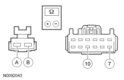 | Yes
INSTALL a new seat control switch. REFER to Seat Control Switch — Front in this section. TEST the system for normal operation. DISCONNECT the battery ground cable. CONNECT driver seat side air bag C367 and driver seat safety belt buckle C3065. REPOWER the SRS . REFER to Section 501-20B . No REPAIR the circuit. TEST the system for normal operation. DISCONNECT the battery ground cable. CONNECT driver seat side air bag C367 and driver seat safety belt buckle C3065. REPOWER the SRS . REFER to Section 501-20B . |
Pinpoint Test AF: Functional Test — Third Row Power Seat
Refer to Wiring Diagrams Cell 120 , Power Seats for schematic and connector information.
The Third Row Power Seat Functional Test checks the complete seat for correct operation and functionality. This pinpoint test focuses of those faults which affect operation of both seats.
NOTICE: The following pinpoint test uses a test light to simulate normal circuit loads. Use only the test light recommended in the Special Tools table at the beginning of this section. To avoid connector terminal damage, use the Flex Probe Kit for the test light probe connection to the vehicle. Do not use the test light probe directly on any connector.
NOTE: Verify good battery condition before diagnosing the Power-Fold Seat Module (PFSM) system. Poor battery condition may interfere with PFSM operation. If battery voltage drops below 11 volts, seat movement does not start. If battery voltage drops below 8 volts, a started seat movement stops.
NOTE: The demand lighting/ battery saver system times-out after 10 minutes and disables the third row power seat operation. Meter voltage measurements may be inaccurate when this occurs, which could lead to misdiagnosis . To enable the demand lighting/ battery saver system during diagnosis and testing, close and open any vehicle door.
NOTE: Very cold weather conditions can cause the power-fold mechanisms to bind resulting in incorrect seat operation. In cold weather, allow the seat to warm up before checking seat operation.
| Test Step | Result / Action to Take | ||||||||||||||||||||||||||||||||
|---|---|---|---|---|---|---|---|---|---|---|---|---|---|---|---|---|---|---|---|---|---|---|---|---|---|---|---|---|---|---|---|---|---|
| AF1 CHECK SEAT(S) OPERATION | |||||||||||||||||||||||||||||||||
| Yes
If both seats operate to each selected position correctly, GO to AF2 for additional checks. If only the LH seat does not operate correctly, GO to Pinpoint Test AG . If only the RH seat does not operate correctly, GO to Pinpoint Test AH . If both seats move but neither seat correctly obtains all the selected positions, GO to AF19 . No GO to AF3 . | ||||||||||||||||||||||||||||||||
| AF2 CHECK THE OPERATION OF EACH SEAT SEPARATELY | |||||||||||||||||||||||||||||||||
| Yes
The system is operating correctly at this time. CHECK for causes of an intermittent concern such as loose, corroded or disconnected connectors, pinched or damaged wiring and REPAIR as necessary. No GO to AF13 . | ||||||||||||||||||||||||||||||||
| AF3 CHECK THE BCM FOR DTCs | |||||||||||||||||||||||||||||||||
| Yes
For DTC B1317:11 or B1317:15, GO to AF10 . For any other DTCs, REFER to Section 419-10 . No GO to AF4 . | ||||||||||||||||||||||||||||||||
| AF4 CHECK FOR VOLTAGE AND GROUND TO THE PFSM | |||||||||||||||||||||||||||||||||
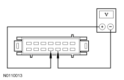 | Yes
GO to AF12 . No GO to AF5 . | ||||||||||||||||||||||||||||||||
| AF5 CHECK THE PFSM FOR VOLTAGE | |||||||||||||||||||||||||||||||||
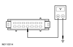 | Yes
REPAIR circuit GD349 (BK/GY) for an open. TEST the system for normal operation. No GO to AF6 . | ||||||||||||||||||||||||||||||||
| AF6 CHECK THE THIRD ROW POWER SEAT RELAY FOR VOLTAGE AND GROUND | |||||||||||||||||||||||||||||||||
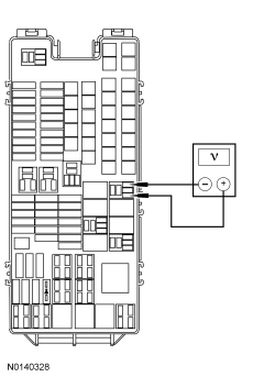 | Yes
GO to AF8 . No GO to AF7 . | ||||||||||||||||||||||||||||||||
| AF7 CHECK THE THIRD ROW POWER SEAT RELAY FOR VOLTAGE | |||||||||||||||||||||||||||||||||
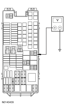 | Yes
REPAIR circuit GD120 (BK/GN) for an open. TEST the system for normal operation. No REPAIR circuit CLN09 (YE/GN). TEST the system for normal operation. | ||||||||||||||||||||||||||||||||
| AF8 CHECK THE THIRD ROW POWER SEAT RELAY FOR VOLTAGE | |||||||||||||||||||||||||||||||||
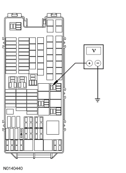 | Yes
GO to AF9 . No VERIFY Battery Junction Box (BJB) fuse 22 (30A) is OK. If the fuse is OK, REPAIR the circuit. If not OK, REFER to the Wiring Diagrams manual to identify possible causes of the circuit short. TEST the system for normal operation. | ||||||||||||||||||||||||||||||||
| AF9 CHECK THE CIRCUIT BETWEEN THE PFSM AND THE THIRD ROW POWER SEAT RELAY FOR AN OPEN | |||||||||||||||||||||||||||||||||
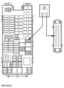 | Yes
INSTALL a new third row power seat relay. TEST the system for normal operation. No REPAIR the circuit. TEST the system for normal operation. | ||||||||||||||||||||||||||||||||
| AF10 CHECK THE PFSM ENABLE CIRCUIT FOR A SHORT TO VOLTAGE | |||||||||||||||||||||||||||||||||
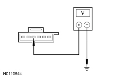 | Yes
REPAIR the circuit. CLEAR the DTCs. REPEAT the self-test. TEST the system for normal operation. No GO to AF11 . | ||||||||||||||||||||||||||||||||
| AF11 CHECK THE PFSM ENABLE CIRCUIT FOR AN OPEN AND SHORT TO GROUND | |||||||||||||||||||||||||||||||||
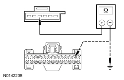 | Yes
GO to AF21 . No REPAIR the circuit. CLEAR the DTCs. REPEAT the self-test. TEST the system for normal operation. | ||||||||||||||||||||||||||||||||
| AF12 CHECK THE PFSM ENABLE CIRCUIT FOR VOLTAGE | |||||||||||||||||||||||||||||||||
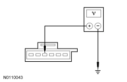 | Yes
GO to AF13 . No GO to AF21 . | ||||||||||||||||||||||||||||||||
| AF13 CHECK FOR VOLTAGE TO THE SEAT CONTROL SWITCH | |||||||||||||||||||||||||||||||||
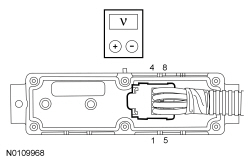 | Yes
GO to AF18 . No GO to AF14 . | ||||||||||||||||||||||||||||||||
| AF14 CHECK CIRCUITS FOR VOLTAGE WITH THE SEAT CONTROL SWITCH DISCONNECTED | |||||||||||||||||||||||||||||||||
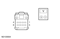 | Yes
INSTALL a new seat control switch. REFER to Seat Control Switch — Third Row in this section. TEST the system for normal operation. No GO to AF15 . | ||||||||||||||||||||||||||||||||
| AF15 CHECK THE SEAT CONTROL SWITCH CIRCUITS FOR A SHORT TO VOLTAGE | |||||||||||||||||||||||||||||||||
 | Yes
REPAIR the circuit(s). TEST the system for normal operation. No GO to AF16 . | ||||||||||||||||||||||||||||||||
| AF16 CHECK THE SEAT CONTROL SWITCH CIRCUITS FOR AN OPEN OR SHORT TO GROUND | |||||||||||||||||||||||||||||||||
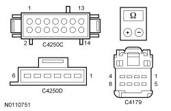 | Yes
GO to AF17 . No REPAIR the affected circuit(s). TEST the system for normal operation. | ||||||||||||||||||||||||||||||||
| AF17 CHECK THE SEAT CONTROL SWITCH CIRCUITS FOR A SHORT TOGETHER | |||||||||||||||||||||||||||||||||
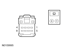 | Yes
GO to AF22 . No REPAIR the affected circuit(s). TEST the system for normal operation. | ||||||||||||||||||||||||||||||||
| AF18 CHECK THE VOLTAGE AT THE SEAT CONTROL SWITCH CIRCUITS | |||||||||||||||||||||||||||||||||
NOTE: C4250E must be disconnected or inaccurate meter measurements may be taken.
 | Yes
GO to AF22 . No INSTALL a new seat control switch. REFER to Seat Control Switch — Third Row in this section. TEST the system for normal operation. | ||||||||||||||||||||||||||||||||
| AF19 CHECK THE SEAT CONTROL SWITCH CIRCUITS FOR A SHORT TOGETHER | |||||||||||||||||||||||||||||||||
 | Yes
GO to AF20 . No REPAIR the affected circuit(s). TEST the system for normal operation. | ||||||||||||||||||||||||||||||||
| AF20 CHECK THE LATCH SWITCH AND LATCH MOTOR RETURN CIRCUITS FOR AN OPEN | |||||||||||||||||||||||||||||||||
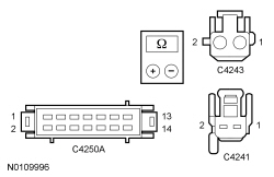 | Yes
GO to AF22 . No REPAIR the affected circuit(s). TEST the system for normal operation. | ||||||||||||||||||||||||||||||||
| AF21 CHECK BCM CONNECTORS AND PINS FOR DAMAGE AND RETEST THE SYSTEM | |||||||||||||||||||||||||||||||||
| Yes
INSTALL a new BCM . REFER to Section 419-10 . TEST the system for normal operation. No The system is operating correctly at this time. The concern may have been caused by a loose or corroded connector. | ||||||||||||||||||||||||||||||||
| AF22 CHECK PFSM CONNECTORS AND PINS FOR DAMAGE AND RETEST THE SYSTEM | |||||||||||||||||||||||||||||||||
| Yes
INSTALL a new PFSM . Refer to Power-Fold Seat Module (PFSM) in this section. TEST the system for normal operation. No The system is operating correctly at this time. The concern may have been caused by a loose or corroded connector. |
Pinpoint Test AG: Seat Latch Motor and Latch Switch Functional Test — LH Third Row Power Seat
Refer to Wiring Diagrams Cell 120 , Power Seats for schematic and connector information.
The Power-Fold Seat Module (PFSM) supplies voltage and ground to the seat latch release motor to electronically release the seat latch from the latched position (seat folded and latched to the floor) when the third row seat control switch sends a signal to the PFSM to move the seat to the STOW or TAILGATE position. The PFSM monitors the latch switch to determine if the position of the latch is closed or released. If the seat latch does not release, the latch must be mechanically released to move the seat from the latched home position. If a fault is detected during a seat operation the seat may enter a faulted state. When the seat is in a faulted state the seat backrest and cushion fold together to prevent the seat from being occupied.
NOTICE: The following pinpoint test uses a test light to simulate normal circuit loads. Use only the test light recommended in the Special Tools table at the beginning of this section. To avoid connector terminal damage, use the Flex Probe Kit for the test light probe connection to the vehicle. Do not use the test light probe directly on any connector.
NOTE: Verify good battery condition before diagnosing the Power-Fold Seat Module (PFSM) system. Poor battery condition may interfere with PFSM operation. If battery voltage drops below 11 volts, seat movement does not start. If battery voltage drops below 8 volts, a started seat movement stops.
NOTE: The demand lighting/battery saver system times-out after 10 minutes and disables the third row power seat operation. Meter voltage measurements may be inaccurate when this occurs, which could lead to misdiagnosis . To enable the accessory delay system during diagnosis and testing, close and open any vehicle door.
| Test Step | Result / Action to Take | |||||||||||||||||||||||||||
|---|---|---|---|---|---|---|---|---|---|---|---|---|---|---|---|---|---|---|---|---|---|---|---|---|---|---|---|---|
| AG1 CONFIRM THE FUNCTIONAL TEST HAS BEEN COMPLETED | ||||||||||||||||||||||||||||
| Yes
GO to AG2 . No CARRY OUT the Functional Test — Third Row Power Seat. GO to Pinpoint Test AF and return to this test only if directed to do so. | |||||||||||||||||||||||||||
| AG2 CHECK FOR AUDIBLE SEAT LATCH OPERATION | ||||||||||||||||||||||||||||
| Yes
GO to AG7 . No GO to AG3 . | |||||||||||||||||||||||||||
| AG3 CHECK THE PFSM FOR OUTPUT VOLTAGE TO THE SEAT LATCH MOTOR | ||||||||||||||||||||||||||||
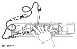 | Yes
GO to AG4 . No GO to AG5 . | |||||||||||||||||||||||||||
| AG4 CHECK THE SEAT LATCH MOTOR CIRCUITS FOR AN OPEN | ||||||||||||||||||||||||||||
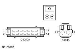 | Yes
INSTALL a new power seat latch. REFER to Seat Latch — Third Row, Power in this section. TEST the system for normal operation. No REPAIR the affected circuit(s). TEST the system for normal operation. | |||||||||||||||||||||||||||
| AG5 CHECK THE SEAT LATCH MOTOR AND CIRCUIT FOR A SHORT TO GROUND | ||||||||||||||||||||||||||||
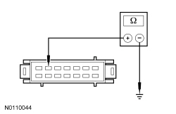 | Yes
GO to AG13 . No GO to AG6 . | |||||||||||||||||||||||||||
| AG6 CHECK THE SEAT LATCH MOTOR CIRCUIT FOR A SHORT TO GROUND | ||||||||||||||||||||||||||||
 | Yes
INSTALL a new power seat latch. Refer to Seat Latch — Third Row, Power in this section. TEST the system for normal operation. No REPAIR the circuit. TEST the system for normal operation. | |||||||||||||||||||||||||||
| AG7 CHECK THE SEAT LATCH SWITCH AND CIRCUITS FOR A SHORT TO GROUND | ||||||||||||||||||||||||||||
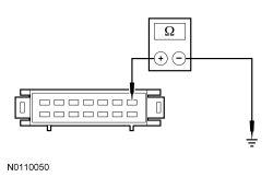 | Yes
GO to AG9 . No GO to AG8 . | |||||||||||||||||||||||||||
| AG8 CHECK THE SEAT LATCH SWITCH CIRCUITS FOR A SHORT TO GROUND OR SHORT TOGETHER | ||||||||||||||||||||||||||||
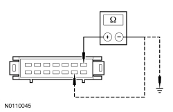 | Yes
INSTALL a new power seat latch. REFER to Seat Latch — Third Row, Power in this section. TEST the system for normal operation. No REPAIR the affected circuit(s). TEST the system for normal operation. | |||||||||||||||||||||||||||
| AG9 CHECK THE SEAT LATCH SWITCH AND CIRCUITS FOR AN OPEN | ||||||||||||||||||||||||||||
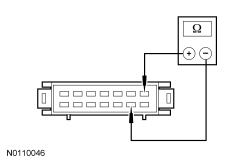 | Yes
GO to AG11 . No GO to AG10 . | |||||||||||||||||||||||||||
| AG10 CHECK THE SEAT LATCH SWITCH CIRCUITS FOR AN OPEN | ||||||||||||||||||||||||||||
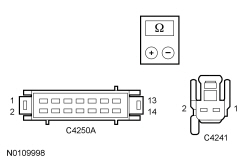 | Yes
INSTALL a new power seat latch. REFER to Seat Latch — Third Row, Power in this section. TEST the system for normal operation. No REPAIR the affected circuit(s). TEST the system for normal operation. | |||||||||||||||||||||||||||
| AG11 CHECK THE SEAT LATCH SWITCH CIRCUIT FOR VOLTAGE AT THE PFSM | ||||||||||||||||||||||||||||
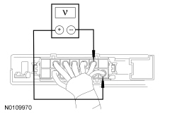 | Yes
The latch assembly checks OK. GO to AG12 . No GO to AG13 . | |||||||||||||||||||||||||||
| AG12 IDENTIFY THE SEAT FUNCTION(S) USING THE TABLE AND DETERMINE THE DIAGNOSTIC DIRECTION | ||||||||||||||||||||||||||||
| Yes
The fault is not present and cannot be recreated at this time. Do not install any new components at this time. Components should only be installed when directed to do so in the pinpoint test. GO to AG13 . No To check the power-stow seat motor, stow sensor and circuits, GO to Pinpoint Test AI . To check the power-fold seat motor (backrest), fold sensor and circuits, GO to Pinpoint Test AK . | |||||||||||||||||||||||||||
| AG13 CHECK PFSM CONNECTORS AND PINS FOR DAMAGE AND RETEST THE SYSTEM | ||||||||||||||||||||||||||||
| Yes
INSTALL a new PFSM . Refer to Power-Fold Seat Module (PFSM) in this section. TEST the system for normal operation. No The system is operating correctly at this time. The concern may have been caused by a loose or corroded connector. |
Pinpoint Test AH: Seat Latch Motor and Latch Switch Functional Test — RH Third Row Power Seat
Refer to Wiring Diagrams Cell 120 , Power Seats for schematic and connector information.
The Power-Fold Seat Module (PFSM) supplies voltage and ground to the seat latch release motor to electronically release the seat latch from the latched position (seat folded and latched to the floor) when the third row seat control switch sends a signal to the PFSM to move the seat to the STOW or TAILGATE position. The PFSM monitors the latch switch to determine if the position of the latch is closed or released. If the seat latch does not release, the latch must be mechanically released to move the seat from the latched home position. If a fault is detected during a seat operation the seat may enter a faulted state. When the seat is in a faulted state the seat backrest and cushion folds together to prevent the seat from being occupied.
NOTICE: The following pinpoint test uses a test light to simulate normal circuit loads. Use only the test light recommended in the Special Tools table at the beginning of this section. To avoid connector terminal damage, use the Flex Probe Kit for the test light probe connection to the vehicle. Do not use the test light probe directly on any connector.
NOTE: Verify good battery condition before diagnosing the Power-Fold Seat Module (PFSM) system. Poor battery condition may interfere with PFSM operation. If battery voltage drops below 11 volts, seat movement does not start. If battery voltage drops below 8 volts, a started seat movement stops.
NOTE: The demand lighting/battery saver system times-out after 10 minutes and disables the third row power seat operation. Meter voltage measurements may be inaccurate when this occurs, which could lead to misdiagnosis . To enable the accessory delay system during diagnosis and testing, close and open any vehicle door.
| Test Step | Result / Action to Take | |||||||||||||||||||||||||||
|---|---|---|---|---|---|---|---|---|---|---|---|---|---|---|---|---|---|---|---|---|---|---|---|---|---|---|---|---|
| AH1 CONFIRM THE SYSTEM FUNCTIONAL TEST HAS BEEN COMPLETED | ||||||||||||||||||||||||||||
| Yes
GO to AH2 . No CARRY OUT the Functional Test — Third Row Power Seat. GO to Pinpoint Test AF and return to this test only if directed to do so. | |||||||||||||||||||||||||||
| AH2 CHECK FOR AUDIBLE SEAT LATCH OPERATION | ||||||||||||||||||||||||||||
| Yes
GO to AH7 . No GO to AH3 . | |||||||||||||||||||||||||||
| AH3 CHECK THE PFSM FOR OUTPUT VOLTAGE TO THE SEAT LATCH MOTOR | ||||||||||||||||||||||||||||
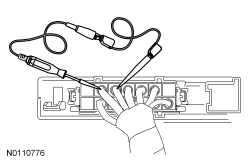 | Yes
GO to AH4 . No GO to AH5 . | |||||||||||||||||||||||||||
| AH4 CHECK THE SEAT LATCH MOTOR CIRCUITS FOR AN OPEN | ||||||||||||||||||||||||||||
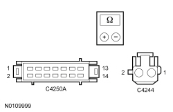 | Yes
INSTALL a new power seat latch. Refer to Seat Latch — Third Row, Power in this section. TEST the system for normal operation. No REPAIR the affected circuit(s). TEST the system for normal operation. | |||||||||||||||||||||||||||
| AH5 CHECK THE SEAT LATCH MOTOR AND CIRCUIT FOR A SHORT TO GROUND | ||||||||||||||||||||||||||||
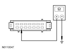 | Yes
GO to AH13 . No GO to AH6 . | |||||||||||||||||||||||||||
| AH6 CHECK THE SEAT LATCH MOTOR CIRCUIT FOR A SHORT TO GROUND | ||||||||||||||||||||||||||||
 | Yes
INSTALL a new power seat latch. Refer to Seat Latch — Third Row, Power in this section. TEST the system for normal operation. No REPAIR the circuit. TEST the system for normal operation. | |||||||||||||||||||||||||||
| AH7 CHECK THE SEAT LATCH SWITCH AND CIRCUITS FOR A SHORT TO GROUND | ||||||||||||||||||||||||||||
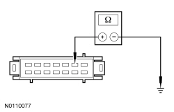 | Yes
GO to AH9 . No GO to AH8 . | |||||||||||||||||||||||||||
| AH8 CHECK THE SEAT LATCH SWITCH CIRCUITS FOR A SHORT TO GROUND OR SHORT TOGETHER | ||||||||||||||||||||||||||||
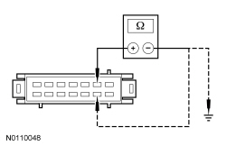 | Yes
INSTALL a new power seat latch. Refer to Seat Latch — Third Row, Power in this section. TEST the system for normal operation. No REPAIR the affected circuit(s). TEST the system for normal operation. | |||||||||||||||||||||||||||
| AH9 CHECK THE SEAT LATCH SWITCH AND CIRCUITS FOR AN OPEN | ||||||||||||||||||||||||||||
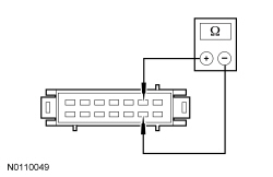 | Yes
GO to AH11 . No GO to AH10 . | |||||||||||||||||||||||||||
| AH10 CHECK THE SEAT LATCH SWITCH CIRCUITS FOR AN OPEN | ||||||||||||||||||||||||||||
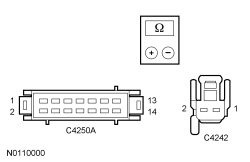 | Yes
INSTALL a new power seat latch. REFER to Seat Latch — Third Row, Power in this section. TEST the system for normal operation. No REPAIR the affected circuit(s). TEST the system for normal operation. | |||||||||||||||||||||||||||
| AH11 CHECK THE SEAT LATCH SWITCH CIRCUIT FOR VOLTAGE AT THE PFSM | ||||||||||||||||||||||||||||
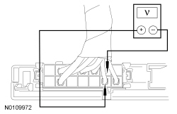 | Yes
The latch assembly checks OK. GO to AH12 . No GO to AH13 . | |||||||||||||||||||||||||||
| AH12 IDENTIFY THE SEAT FUNCTION(S) USING THE TABLE AND DETERMINE THE DIAGNOSTIC DIRECTION | ||||||||||||||||||||||||||||
| Yes
The fault is not present and cannot be recreated at this time. Do not install any new components at this time. Components should only be installed when directed to do so in the pinpoint test. GO to AH13 . No To check the power-stow seat motor, stow sensor and circuits, GO to Pinpoint Test AJ . To check the power-fold seat motor (backrest), fold sensor and circuits, GO to Pinpoint Test AL . | |||||||||||||||||||||||||||
| AH13 CHECK PFSM CONNECTORS AND PINS FOR DAMAGE AND RETEST THE SYSTEM | ||||||||||||||||||||||||||||
| Yes
INSTALL a new PFSM . Refer to Power-Fold Seat Module (PFSM) in this section. TEST the system for normal operation. No The system is operating correctly at this time. The concern may have been caused by a loose or corroded connector. |
Pinpoint Test AI: Power-Stow Seat Motor and Sensor Functional Test — LH Third Row Power Seat
Refer to Wiring Diagrams Cell 120 , Power Seats for schematic and connector information.
The Power-Fold Seat Module (PFSM) supplies voltage and ground to the power-stow seat motor to move the seat to and from the STOW position when selected by the seat control switch. When STOW is selected from NORMAL or TAILGATE, the backrest folds forward to release the spring loaded headrest. If an obstruction is detected in the STOW axis of movement the seat stops, reverses movement a few inches and then stops again until the obstruction is removed. When the obstruction has been removed the seat control switch must be depressed again to reset the request. The seat goes to the power-stow seat motor home position (seat folded and latched to the floor) and then continues with the STOW request. If the PFSM detects an open or short in the power-stow seat motor circuitry, motor operation is disabled. If a short to ground is present the motor works in only one direction.
A Hall effect sensor is located inside each of the power-stow seat motor assemblies to detect power-stow seat motor movement and position to the PFSM . If the sensor does not detect motor movement during a request from the seat control switch, the PFSM disables the power-stow seat motor output. When the seat control switch is pressed again the seat moves in short increments indicating a fault with the sensor or circuitry.
NOTICE: The following pinpoint test uses a test light to simulate normal circuit loads. Use only the test light recommended in the Special Tools table at the beginning of this section. To avoid connector terminal damage, use the Flex Probe Kit for the test light probe connection to the vehicle. Do not use the test light probe directly on any connector.
NOTE: Verify good battery condition before diagnosing the Power-Fold Seat Module (PFSM) system. Poor battery condition may interfere with PFSM operation. If battery voltage drops below 11 volts, seat movement does not start. If battery voltage drops below 8 volts, a started seat movement stops.
NOTE: The demand lighting/battery saver system times-out after 10 minutes and disables the third row power seat operation. Meter voltage measurements may be inaccurate when this occurs, which could lead to misdiagnosis . To enable the accessory delay system during diagnosis and testing, close and open any vehicle door.
| Test Step | Result / Action to Take |
|---|---|
| AI1 CONFIRM THE SYSTEM FUNCTIONAL TEST HAS BEEN COMPLETED | |
| Yes
GO to AI2 . No CARRY OUT the Functional Test — Third Row Power Seat. GO to Pinpoint Test AF and return to this test only if directed to do so. |
| AI2 CHECK THE PFSM FOR OUTPUT VOLTAGE TO THE POWER-STOW SEAT MOTOR | |
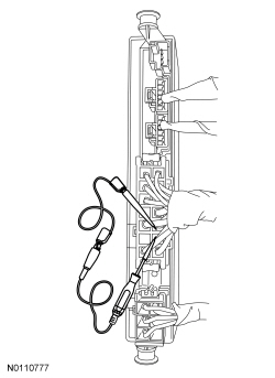 | Yes
GO to AI5 . No GO to AI3 . |
| AI3 CHECK THE LH POWER-STOW SEAT MOTOR AND CIRCUITS FOR A SHORT TO GROUND | |
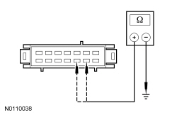 | Yes
GO to AI11 . No GO to AI4 . |
| AI4 CHECK THE LH POWER-STOW SEAT MOTOR AND CIRCUITS FOR A SHORT TO GROUND | |
 | Yes
INSTALL a new power-stow seat motor. REFER to Power-Stow Seat Motor — Third Row in this section. TEST the system for normal operation. No REPAIR the affected circuit(s). TEST the system for normal operation. |
| AI5 CHECK THE LH POWER-STOW SEAT MOTOR AND CIRCUITS FOR AN OPEN | |
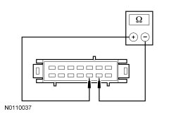 | Yes
GO to AI7 . No GO to AI6 . |
| AI6 CHECK THE POWER-STOW SEAT MOTOR CIRCUITS FOR AN OPEN | |
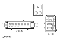 | Yes
INSTALL a new power-stow seat motor. REFER to Power-Stow Seat Motor — Third Row in this section. TEST the system for normal operation. No REPAIR the affected circuit(s). TEST the system for normal operation. |
| AI7 CHECK THE PFSM FOR OUTPUT VOLTAGE TO THE STOW SENSOR | |
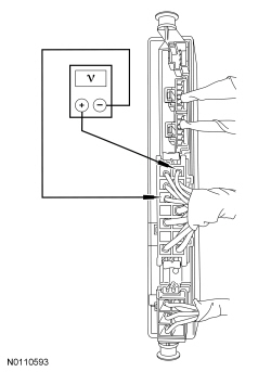 | Yes
GO to AI10 . No GO to AI8 . |
| AI8 CHECK THE LH POWER-STOW SEAT MOTOR SENSOR AND CIRCUIT FOR A SHORT TO GROUND | |
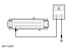 | Yes
GO to AI11 . No GO to AI9 . |
| AI9 CHECK THE LH POWER-STOW SEAT MOTOR SENSOR CIRCUIT FOR A SHORT TO GROUND | |
 | Yes
INSTALL a new power-stow seat motor assembly. REFER to Power-Stow Seat Motor — Third Row in this section. TEST the system for normal operation. No REPAIR the circuit. TEST the system for normal operation. |
| AI10 CHECK THE LH POWER-STOW SEAT MOTOR SENSOR CIRCUITS FOR AN OPEN | |
 | Yes
INSTALL a new power-stow seat motor assembly. REFER to Power-Stow Seat Motor — Third Row in this section. TEST the system for normal operation. No REPAIR the affected circuit(s). TEST the system for normal operation. |
| AI11 CHECK PFSM CONNECTORS AND PINS FOR DAMAGE AND RETEST THE SYSTEM | |
| Yes
INSTALL a new PFSM . Refer to Power-Fold Seat Module (PFSM) in this section. TEST the system for normal operation. No The system is operating correctly at this time. The concern may have been caused by a loose or corroded connector. |
Pinpoint Test AJ: Power-Stow Seat Motor and Sensor Functional Test — RH Third Row Power Seat
Refer to Wiring Diagrams Cell 120 , Power Seats for schematic and connector information.
The Power-Fold Seat Module (PFSM) supplies voltage and ground to the power-stow seat motor to move the seat to and from the STOW position when selected by the seat control switch. When STOW is selected from NORMAL or TAILGATE, the backrest folds forward to release the spring loaded headrest. If an obstruction is detected in the STOW axis of movement the seat stops, reverses movement a few inches and then stops again until the obstruction is removed. When the obstruction has been removed the seat control switch must be depressed again to reset the request. The seat goes to the power-stow seat motor home position (seat folded and latched to the floor) and then continues with the STOW request. If the PFSM detects an open or short in the power-stow seat motor circuitry, motor operation is disabled. If a short to ground is present the motor works in only one direction.
A Hall effect sensor is located inside each of the power-stow seat motor assemblies to detect power-stow seat motor movement and position to the PFSM . If the sensor does not detect motor movement during a request from the seat control switch, the PFSM disables the power-stow seat motor output. When the seat control switch is pressed again the seat moves in short increments indicating a fault with the sensor or circuitry.
NOTICE: The following pinpoint test uses a test light to simulate normal circuit loads. Use only the test light recommended in the Special Tools table at the beginning of this section. To avoid connector terminal damage, use the Flex Probe Kit for the test light probe connection to the vehicle. Do not use the test light probe directly on any connector.
NOTE: Verify good battery condition before diagnosing the Power-Fold Seat Module (PFSM) system. Poor battery condition may interfere with PFSM operation. If battery voltage drops below 11 volts, seat movement does not start. If battery voltage drops below 8 volts, a started seat movement stops.
NOTE: The demand lighting/battery saver system times-out after 10 minutes and disables the third row power seat operation. Meter voltage measurements may be inaccurate when this occurs, which could lead to misdiagnosis . To enable the accessory delay system during diagnosis and testing, close and open any vehicle door.
| Test Step | Result / Action to Take |
|---|---|
| AJ1 CONFIRM THE SYSTEM FUNCTIONAL TEST HAS BEEN COMPLETED | |
| Yes
GO to AJ2 . No CARRY OUT the Functional Test — Third Row Power Seat. GO to Pinpoint Test AF and return to this test only if directed to do so. |
| AJ2 CHECK THE PFSM FOR OUTPUT VOLTAGE TO THE POWER-STOW SEAT MOTOR | |
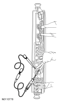 | Yes
GO to AJ5 . No GO to AJ3 . |
| AJ3 CHECK THE POWER-STOW SEAT MOTOR AND CIRCUITS FOR A SHORT TO GROUND | |
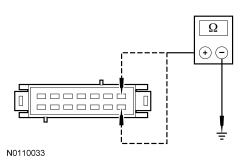 | Yes
GO to AJ11 . No GO to AJ4 . |
| AJ4 CHECK THE POWER-STOW SEAT MOTOR AND CIRCUITS FOR A SHORT TO GROUND | |
 | Yes
INSTALL a new power-stow seat motor. REFER to Power-Stow Seat Motor — Third Row in this section. REFER to Power-Stow Seat Motor — Third Row in this section. TEST the system for normal operation. No REPAIR the affected circuit(s). TEST the system for normal operation. |
| AJ5 CHECK THE POWER-STOW SEAT MOTOR AND CIRCUITS FOR AN OPEN | |
 | Yes
GO to AJ7 . No GO to AJ6 . |
| AJ6 CHECK THE POWER-STOW SEAT MOTOR CIRCUITS FOR AN OPEN | |
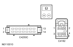 | Yes
INSTALL a new power-stow seat motor. REFER to Power-Stow Seat Motor — Third Row in this section. TEST the system for normal operation. No REPAIR the affected circuit(s). TEST the system for normal operation. |
| AJ7 CHECK THE PFSM FOR OUTPUT VOLTAGE TO THE STOW SENSOR | |
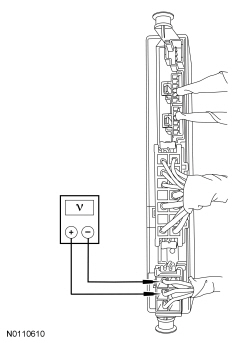 | Yes
GO to AJ10 . No GO to AJ8 . |
| AJ8 CHECK THE STOW SENSOR AND CIRCUIT FOR A SHORT TO GROUND | |
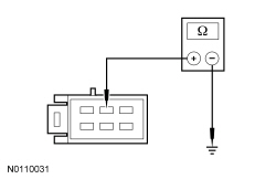 | Yes
GO to AJ11 . No GO to AJ9 . |
| AJ9 CHECK THE STOW SENSOR CIRCUIT FOR A SHORT TO GROUND | |
 | Yes
INSTALL a new power-stow seat motor assembly. REFER to Power-Stow Seat Motor — Third Row in this section. TEST the system for normal operation. No REPAIR the circuit. TEST the system for normal operation. |
| AJ10 CHECK THE STOW SENSOR CIRCUITS FOR AN OPEN | |
 | Yes
INSTALL a new power-stow seat motor assembly. REFER to Power-Stow Seat Motor — Third Row in this section. TEST the system for normal operation. No REPAIR the affected circuit(s). TEST the system for normal operation. |
| AJ11 CHECK PFSM CONNECTORS AND PINS FOR DAMAGE AND RETEST THE SYSTEM | |
| Yes
INSTALL a new PFSM . Refer to Power-Fold Seat Module (PFSM) in this section. TEST the system for normal operation. No The system is operating correctly at this time. The concern may have been caused by a loose or corroded connector. |
Pinpoint Test AK: Power-Fold Seat Motor (Backrest) and Sensor Functional Test — LH Third Row Power Seat
Refer to Wiring Diagrams Cell 120 , Power Seats for schematic and connector information.
The Power-Fold Seat Module (PFSM) supplies voltage and ground to the power-fold seat motor to move the seat to and from the FOLD and NORMAL positions when selected by the seat control switch. When FOLD is selected the backrest folds forward and releases the spring loaded headrest. If an obstruction is detected in the FOLD/NORMAL axis of movement the seat stops, reverses movement a few inches and then stops again until the obstruction is removed. When the obstruction has been removed the seat control switch must be depressed again to reset the request. The seat goes to the power-fold seat motor home position (seat folded and latched to floor) and then continues with any seat position requested. If the PFSM detects a power-fold seat motor circuit fault (open or short), motor operation is disabled. If a short to ground is present the motor works in only one direction.
A Hall effect sensor is located inside each of the power-fold seat motor assemblies to detect motor movement and seat position to the PFSM . If the sensor does not detect motor movement during a request from the seat control switch, the PFSM disables the power-fold seat motor output.
NOTICE: The following pinpoint test uses a test light to simulate normal circuit loads. Use only the test light recommended in the Special Tools table at the beginning of this section. To avoid connector terminal damage, use the Flex Probe Kit for the test light probe connection to the vehicle. Do not use the test light probe directly on any connector.
NOTE: Verify good battery condition before diagnosing the Power-Fold Seat Module (PFSM) system. Poor battery condition may interfere with PFSM operation. If battery voltage drops below 11 volts, seat movement does not start. If battery voltage drops below 8 volts, a started seat movement stops.
NOTE: The demand lighting/battery saver system times-out after 10 minutes and disables the third row power seat operation. Meter voltage measurements may be inaccurate when this occurs, which could lead to misdiagnosis . To enable the accessory delay system during diagnosis and testing, close and open any vehicle door.
| Test Step | Result / Action to Take |
|---|---|
| AK1 CONFIRM THE FUNCTIONAL TEST HAS BEEN COMPLETED | |
| Yes
GO to AK2 . No CARRY OUT the Functional Test — Third Row Power Seat. GO to Pinpoint Test AF and return to this test only if directed to do so. |
| AK2 CHECK THE PFSM FOR OUTPUT VOLTAGE TO THE POWER-FOLD SEAT MOTOR | |
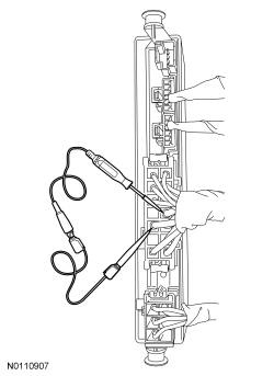 | Yes
GO to AK5 . No GO to AK3 . |
| AK3 CHECK THE POWER-FOLD SEAT MOTOR AND CIRCUITS FOR A SHORT TO GROUND | |
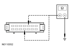 | Yes
GO to AK11 . No GO to AK4 . |
| AK4 CHECK THE POWER-FOLD SEAT MOTOR AND CIRCUITS FOR A SHORT TO GROUND | |
 | Yes
INSTALL a new power-fold seat motor. REFER to Power-Fold Seat Motor — Third Row in this section. TEST the system for normal operation. No REPAIR the affected circuit(s). TEST the system for normal operation. |
| AK5 CHECK THE POWER-FOLD SEAT MOTOR AND CIRCUITS FOR AN OPEN | |
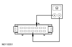 | Yes
GO to AK7 . No GO to AK6 . |
| AK6 CHECK THE POWER-FOLD SEAT MOTOR CIRCUITS FOR AN OPEN | |
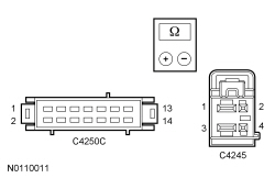 | Yes
INSTALL a new power-fold seat motor. REFER to Power-Fold Seat Motor — Third Row in this section. TEST the system for normal operation. No REPAIR the affected circuit(s). TEST the system for normal operation. |
| AK7 CHECK THE PFSM FOR OUTPUT VOLTAGE TO THE FOLD SENSOR | |
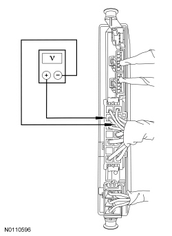 | Yes
GO to AK10 . No GO to AK8 . |
| AK8 CHECK THE FOLD SENSOR AND CIRCUIT FOR A SHORT TO GROUND | |
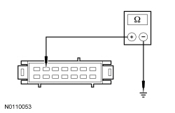 | Yes
GO to AK11 . No GO to AK9 . |
| AK9 CHECK THE FOLD SENSOR CIRCUIT FOR A SHORT TO GROUND | |
 | Yes
INSTALL a new power-fold seat motor assembly. REFER to Power-Fold Seat Motor — Third Row in this section. TEST the system for normal operation. No REPAIR the circuit. TEST the system for normal operation. |
| AK10 CHECK THE FOLD SENSOR CIRCUITS FOR AN OPEN | |
 | Yes
INSTALL a new power-fold seat motor assembly. REFER to Power-Fold Seat Motor — Third Row in this section. TEST the system for normal operation. No REPAIR the affected circuit(s). TEST the system for normal operation. |
| AK11 CHECK PFSM CONNECTORS AND PINS FOR DAMAGE AND RETEST THE SYSTEM | |
| Yes
INSTALL a new PFSM . Refer to Power-Fold Seat Module (PFSM) in this section. TEST the system for normal operation. No The system is operating correctly at this time. The concern may have been caused by a loose or corroded connector. |
Pinpoint Test AL: Power-Fold Seat Motor (Backrest) and Sensor Functional Test — RH Third Row Power Seat
Refer to Wiring Diagrams Cell 120 , Power Seats for schematic and connector information.
The Power-Fold Seat Module (PFSM) supplies voltage and ground to the power-fold seat motor to move the seat to and from the FOLD and NORMAL positions when selected by the seat control switch. When FOLD is selected the backrest folds forward and releases the spring loaded headrest. If an obstruction is detected in the FOLD/NORMAL axis of movement the seat stops, reverses movement a few inches and then stops again until the obstruction is removed. When the obstruction has been removed the seat control switch must be depressed again to reset the request. The seat goes to the power-fold seat motor home position (seat folded and latched to floor) and then continues with any seat position requested. If the PFSM detects a power-fold seat motor circuit fault (open or short), motor operation is disabled. If a short to ground is present the motor works in only one direction.
A Hall effect sensor is located inside each of the power-fold seat motor assemblies to detect motor movement and seat position to the PFSM . If the sensor does not detect motor movement during a request from the seat control switch, the PFSM disables the power-fold seat motor output.
NOTICE: The following pinpoint test uses a test light to simulate normal circuit loads. Use only the test light recommended in the Special Tools table at the beginning of this section. To avoid connector terminal damage, use the Flex Probe Kit for the test light probe connection to the vehicle. Do not use the test light probe directly on any connector.
NOTE: Verify good battery condition before diagnosing the Power-Fold Seat Module (PFSM) system. Poor battery condition may interfere with PFSM operation. If battery voltage drops below 11 volts, seat movement does not start. If battery voltage drops below 8 volts, a started seat movement stops.
NOTE: The demand lighting/battery saver system times-out after 10 minutes and disables the third row power seat operation. Meter voltage measurements may be inaccurate when this occurs, which could lead to misdiagnosis . To enable the accessory delay system during diagnosis and testing, close and open any vehicle door.
| Test Step | Result / Action to Take |
|---|---|
| AL1 CONFIRM THE FUNCTIONAL TEST HAS BEEN COMPLETED | |
| Yes
GO to AL2 . No CARRY OUT the Functional Test — Third Row Power Seat. GO to Pinpoint Test AF and return to this test only if directed to do so. |
| AL2 CHECK THE PFSM FOR OUTPUT VOLTAGE TO THE POWER-FOLD SEAT MOTOR | |
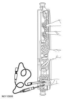 | Yes
GO to AL5 . No GO to AL3 . |
| AL3 CHECK THE POWER-FOLD SEAT MOTOR AND CIRCUITS FOR A SHORT TO GROUND | |
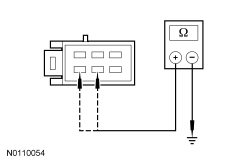 | Yes
GO to AL11 . No GO to AL4 . |
| AL4 CHECK THE POWER-STOW SEAT MOTOR AND CIRCUITS FOR A SHORT TO GROUND | |
 | Yes
INSTALL a new power-fold seat motor. REFER to Power-Fold Seat Motor — Third Row in this section. TEST the system for normal operation. No REPAIR the affected circuit(s). TEST the system for normal operation. |
| AL5 CHECK THE POWER-FOLD SEAT MOTOR AND CIRCUITS FOR AN OPEN | |
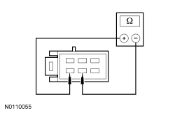 | Yes
GO to AL7 . No GO to AL6 . |
| AL6 CHECK THE POWER-FOLD SEAT MOTOR CIRCUITS FOR AN OPEN | |
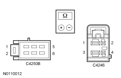 | Yes
INSTALL a new power-fold seat motor. REFER to Power-Fold Seat Motor — Third Row in this section. TEST the system for normal operation. No REPAIR the affected circuit(s). TEST the system for normal operation. |
| AL7 CHECK THE PFSM FOR OUTPUT VOLTAGE TO THE FOLD SENSOR | |
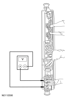 | Yes
GO to AL10 . No GO to AL8 . |
| AL8 CHECK THE FOLD SENSOR AND CIRCUITS FOR A SHORT TO GROUND | |
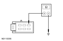 | Yes
GO to AL11 . No GO to AL9 . |
| AL9 CHECK THE FOLD SENSOR CIRCUIT FOR A SHORT TO GROUND | |
 | Yes
INSTALL a new power-fold seat motor assembly. REFER to Power-Fold Seat Motor — Third Row in this section. TEST the system for normal operation. No REPAIR the circuit. TEST the system for normal operation. |
| AL10 CHECK THE FOLD SENSOR CIRCUITS FOR AN OPEN | |
 | Yes
INSTALL a new power-fold seat motor assembly. REFER to Power-Fold Seat Motor — Third Row in this section. TEST the system for normal operation. No REPAIR the affected circuit(s). TEST the system for normal operation. |
| AL11 CHECK PFSM CONNECTORS AND PINS FOR DAMAGE AND RETEST THE SYSTEM | |
| Yes
INSTALL a new PFSM . Refer to Power-Fold Seat Module (PFSM) in this section. TEST the system for normal operation. No The system is operating correctly at this time. The concern may have been caused by a loose or corroded connector. |
Pinpoint Test AM: DTC B106E, B106F
When a repetitive fault causing a circuit overload is detected on certain output circuits, the Driver Seat Module (DSM) disables the circuit by removing voltage, or ground, to the affected circuit. The circuit remains disabled until the fault is corrected and an on-demand self-test is run. When the on-demand self-test has been run after all faults have been corrected, any DTCs related to the fault are cleared.
This pinpoint test is intended to diagnose the following:
NOTICE: If DTC B106F is present and the Driver Seat Module (DSM) is to be replaced, the fault condition must be corrected first. Failure to correct the fault condition first may cause damage to the new DSM , resulting in a repeat repair.
| Test Step | Result / Action to Take |
|---|---|
| AM1 REVIEW THE DTCs | |
| Yes
INSTALL a new DSM . REFER to Driver Seat Module (DSM) in this section. TEST the system for normal operation. No CORRECT any DTCs present other than DTC B106E (DTC B106F may also be present). REFER to DTC Charts in this section. After the repair, GO to AM2 . |
| AM2 CARRY OUT THE DSM SELF-TEST | |
| Yes
INSTALL a new DSM . REFER to Driver Seat Module (DSM) in this section. TEST the system for normal operation. No The system is operating correctly at this time. The concern was caused by a fault in one of the output circuits, which is no longer present. |
Pinpoint Test AN: DTC B1318
Refer to Wiring Diagrams Cell 123 , Memory Seats for schematic and connector information.
The Driver Seat Module (DSM) continuously monitors the input voltage for correct operation. If the DSM detects input voltage below 11 volts, it stores DTC B1318 in memory. If the DSM detects input voltage above 15 volts, it stores DTC B1317 in memory. If DTC B1317 or B1318 is set, the DSM disables the memory system outputs for the driver seat memory operation.
This pinpoint test is intended to diagnose the following:
NOTICE: Use the correct probe adapter(s) when making measurements. Failure to use the correct probe adapter(s) may damage the connector.
NOTE: Failure to disconnect the battery when instructed will result in false resistance readings. Refer to Section 414-01 .
| Test Step | Result / Action to Take |
|---|---|
| AN1 RECHECK THE DSM DTCs | |
| Yes
GO to AN2 . No The system is operating normally at this time. The DTC may have been set previously during battery charging or while jump starting the vehicle. |
| AN2 CHECK FOR CHARGING SYSTEM DTCs IN THE PCM | |
| Yes
REFER to Section 414-00 . No GO to AN3 . |
| AN3 CHECK THE BATTERY CONDITION AND STATE OF CHARGE | |
| Yes
GO to AN4 . No REFER to Section 414-00 . |
| AN4 CHECK THE DSM VOLTAGE SUPPLY | |
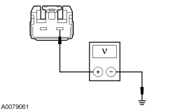 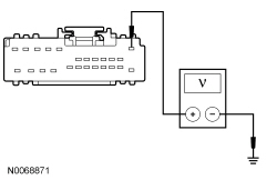 | Yes
GO to AN5 . No REPAIR the circuit for high resistance. CLEAR the DTC. REPEAT the self-test. DISCONNECT the battery ground cable. CONNECT driver seat side air bag C367 and driver seat safety belt buckle C3065. REPOWER the SRS . REFER to Section 501-20B . |
| AN5 CHECK THE DSM GROUND CIRCUIT | |
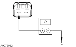 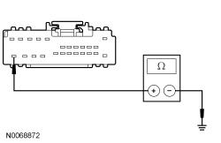 | Yes
CONNECT the negative battery cable. GO to AN6 . No REPAIR the circuit for high resistance. CONNECT the negative battery cable. TEST the system for normal operation. DISCONNECT the battery ground cable. CONNECT driver seat side air bag C367 and driver seat safety belt buckle C3065. REPOWER the SRS . REFER to Section 501-20B . |
| AN6 CHECK FOR CORRECT DSM OPERATION | |
| Yes
INSTALL a new DSM . REFER to Driver Seat Module (DSM) in this section. TEST the system for normal operation. DISCONNECT the battery ground cable. CONNECT driver seat side air bag C367 and driver seat safety belt buckle C3065. REPOWER the SRS . REFER to Section 501-20B . No The system is operating correctly at this time. The concern may have been caused by a loose or corroded connector. DISCONNECT the battery ground cable. CONNECT driver seat side air bag C367 and driver seat safety belt buckle C3065. REPOWER the SRS . REFER to Section 501-20B . |
Pinpoint Test AO: DTC U0140
Refer to Wiring Diagrams Cell 14 , Module Communications Network for schematic and connector information.
The Driver Seat Module (DSM) and the Body Control Module (BCM) communicate using the Medium Speed Controller Area Network (MS-CAN). Messages are exchanged between the modules on the MS-CAN for the purposes of determining what functions are being carried out.
This pinpoint test is intended to diagnose the following:
| Test Step | Result / Action to Take |
|---|---|
| AO1 VERIFY CUSTOMER CONCERN | |
| Yes
GO to AO2 . No The system is operating normally at this time. The DTC may have been set due to high network traffic or an intermittent fault condition. |
| AO2 CHECK THE COMMUNICATION NETWORK | |
| Yes
GO to AO3 . No REFER to Section 418-00 . |
| AO3 RETRIEVE THE RECORDED DTCs FROM THE SELF-TEST | |
| Yes
For DTC B1317, GO to Pinpoint Test AD . For DTC B1318, GO to Pinpoint Test AN . No GO to AO4 . |
| AO4 RECHECK THE DSM DTCs | |
NOTE: If new modules were installed prior to the DTC being set, the module configuration may be incorrectly set during Programmable Module Installation (PMI) or the PMI may not have been carried out. | Yes
GO to AO5 . No The system is operating correctly at this time. The DTC may have been set due to high network traffic or an intermittent fault condition. |
| AO5 CHECK FOR DTC U0140/U0140:00 SET IN OTHER MODULES | |
| Yes
INSTALL a new DSM . REFER to Driver Seat Module (DSM) in this section. No INSTALL a new BCM . REFER to Section 419-10 . |
Pinpoint Test AQ: DTC B19A4
Refer to Wiring Diagrams Cell 119 , Climate Controlled Seats for schematic and connector information.
The Dual Climate Controlled Seat Module (DCSM) supplies voltage and ground to the driver seat backrest Thermo-Electric Device (TED). The DCSM also sends a speed control voltage signal to the TED to control blower speed.
NOTICE: When taking measurements at Dual Climate Controlled Seat Module (DCSM) harness connectors, do not insert the electrical probes into the female connector pins. Inserting the probes into connector pins can cause intermittent or open electrical connections after reassembly resulting in Diagnostic Trouble Codes (DTCs) and system failure. Touching the tip of these connector pins is recommended instead.
NOTE: The air bag warning indicator illuminates when the correct Restraints Control Module (RCM) fuse is removed and the ignition switch is on.
NOTE: The Supplemental Restraint System (SRS) must be fully operational and free of faults before releasing the vehicle to the customer.
| Test Step | Result / Action to Take |
|---|---|
| AQ1 CHECK THE BACKREST TED BLOWER MOTOR SPEED CONTROL CIRCUIT FOR A SHORT TO VOLTAGE | |
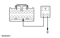 | Yes
GO to AQ2 . No GO to AQ3 . |
| AQ2 CHECK THE BACKREST TED BLOWER MOTOR SPEED CONTROL CIRCUIT FOR A SHORT TO VOLTAGE | |
 | Yes
REPAIR the circuit. CLEAR the DTCs. REPEAT the self-test. DISCONNECT the battery ground cable. CONNECT passenger seat side air bag C337 and passenger safety belt buckle C3066. CONNECT driver seat side air bag C367 and driver safety belt buckle C3065. REPOWER the SRS . REFER to Section 501-20B . No GO to AQ3 . |
| AQ3 CHECK THE BACKREST TED BLOWER MOTOR SPEED CONTROL AND BLOWER MOTOR FEED CIRCUITS FOR A SHORT TOGETHER | |
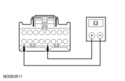 | Yes
GO to AQ4 . No REPAIR the circuits. CLEAR the DTCs. REPEAT the self-test. DISCONNECT the battery ground cable. CONNECT passenger seat side air bag C337 and passenger safety belt buckle C3066. CONNECT driver seat side air bag C367 and driver safety belt buckle C3065. REPOWER the SRS . REFER to Section 501-20B . |
| AQ4 CHECK THE BACKREST TED RESISTANCE FOR AN INTERNAL SHORT | |
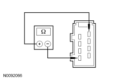 | Yes
INSTALL a new DCSM . REFER to Dual Climate Controlled Seat Module (DCSM) in this section. CLEAR the DTCs. REPEAT the self-test. DISCONNECT the battery ground cable. CONNECT passenger seat side air bag C337 and passenger safety belt buckle C3066. CONNECT driver seat side air bag C367 and driver safety belt buckle C3065. REPOWER the SRS . REFER to Section 501-20B . No INSTALL a new backrest TED . REFER to Seat Backrest Thermo-Electric Device in this section. CLEAR the DTCs. REPEAT the self-test. DISCONNECT the battery ground cable. CONNECT passenger seat side air bag C337 and passenger safety belt buckle C3066. CONNECT driver seat side air bag C367 and driver safety belt buckle C3065. REPOWER the SRS . REFER to Section 501-20B . |
Pinpoint Test AR: DTC B19A5
Refer to Wiring Diagrams Cell 119 , Climate Controlled Seats for schematic and connector information.
The Dual Climate Controlled Seat Module (DCSM) supplies voltage and ground to the passenger seat cushion Thermo-Electric Device (TED). The DCSM also sends a speed control voltage signal to the TED to control blower speed.
NOTICE: When taking measurements at Dual Climate Controlled Seat Module (DCSM) harness connectors, do not insert the electrical probes into the female connector pins. Inserting the probes into connector pins can cause intermittent or open electrical connections after reassembly resulting in Diagnostic Trouble Codes (DTCs) and system failure. Touching the tip of these connector pins is recommended instead.
NOTE: The air bag warning indicator illuminates when the correct Restraints Control Module (RCM) fuse is removed and the ignition switch is on.
NOTE: The Supplemental Restraint System (SRS) must be fully operational and free of faults before releasing the vehicle to the customer.
| Test Step | Result / Action to Take |
|---|---|
| AR1 CHECK THE CUSHION TED BLOWER MOTOR SPEED CONTROL CIRCUIT FOR A SHORT TO GROUND | |
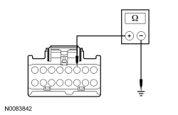 | Yes
GO to AR2 . No REPAIR the circuit. CLEAR the DTCs. REPEAT the self-test. DISCONNECT the battery ground cable. CONNECT passenger seat side air bag C337 and passenger safety belt buckle C3066. REPOWER the SRS . REFER to Section 501-20B . |
| AR2 CHECK THE CUSHION TED BLOWER MOTOR SPEED CONTROL AND BLOWER MOTOR GROUND CIRCUITS FOR A SHORT TOGETHER | |
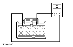 | Yes
INSTALL a new cushion TED . REFER to Seat Cushion Thermo-Electric Device in this section. CLEAR the DTCs. REPEAT the self-test. If the DTC is retrieved again, INSTALL a new DCSM . REFER to Dual Climate Controlled Seat Module (DCSM) in this section. CLEAR the DTCs. REPEAT the self-test. DISCONNECT the battery ground cable. CONNECT passenger seat side air bag C337 and passenger safety belt buckle C3066. REPOWER the SRS . REFER to Section 501-20B . No REPAIR the circuits. CLEAR the DTCs. REPEAT the self-test. DISCONNECT the battery ground cable. CONNECT passenger seat side air bag C337 and passenger safety belt buckle C3066. REPOWER the SRS . REFER to Section 501-20B . |
Pinpoint Test AS: DTC B19A6
Refer to Wiring Diagrams Cell 119 , Climate Controlled Seats for schematic and connector information.
The Dual Climate Controlled Seat Module (DCSM) supplies voltage and ground to the passenger seat backrest Thermo-Electric Device (TED). The DCSM also sends a speed control voltage signal to the TED to control blower speed.
NOTICE: When taking measurements at Dual Climate Controlled Seat Module (DCSM) harness connectors, do not insert the electrical probes into the female connector pins. Inserting the probes into connector pins can cause intermittent or open electrical connections after reassembly resulting in Diagnostic Trouble Codes (DTCs) and system failure. Touching the tip of these connector pins is recommended instead.
NOTE: The air bag warning indicator illuminates when the correct Restraints Control Module (RCM) fuse is removed and the ignition switch is on.
NOTE: The Supplemental Restraint System (SRS) must be fully operational and free of faults before releasing the vehicle to the customer.
| Test Step | Result / Action to Take |
|---|---|
| AS1 CHECK THE BACKREST TED BLOWER SPEED CONTROL CIRCUIT FOR A SHORT TO GROUND | |
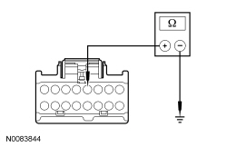 | Yes
GO to AS2 . No REPAIR the circuit. CLEAR the DTCs. REPEAT the self-test. DISCONNECT the battery ground cable. CONNECT passenger seat side air bag C337 and passenger safety belt buckle C3066. REPOWER the SRS . REFER to Section 501-20B . |
| AS2 CHECK THE BACKREST TED BLOWER MOTOR SPEED CONTROL AND BLOWER MOTOR GROUND CIRCUITS FOR A SHORT TOGETHER | |
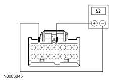 | Yes
INSTALL a new backrest TED . REFER to Seat Backrest Thermo-Electric Device in this section. CLEAR the DTCs. REPEAT the self-test. If the DTC is retrieved again, INSTALL a new DCSM . REFER to Dual Climate Controlled Seat Module (DCSM) in this section. CLEAR the DTCs. REPEAT the self-test. DISCONNECT the battery ground cable. CONNECT passenger seat side air bag C337 and passenger safety belt buckle C3066. REPOWER the SRS . REFER to Section 501-20B . No REPAIR the circuits. CLEAR the DTCs. REPEAT the self-test. DISCONNECT the battery ground cable. CONNECT passenger seat side air bag C337 and passenger safety belt buckle C3066. REPOWER the SRS . REFER to Section 501-20B . |
Pinpoint Test AT: DTC B19A7
Refer to Wiring Diagrams Cell 119 , Climate Controlled Seats for schematic and connector information.
The Dual Climate Controlled Seat Module (DCSM) supplies voltage and ground to the driver seat cushion Thermo-Electric Device (TED). The DCSM also sends a speed control voltage signal to the TED to control blower speed.
NOTICE: When taking measurements at Dual Climate Controlled Seat Module (DCSM) harness connectors, do not insert the electrical probes into the female connector pins. Inserting the probes into connector pins can cause intermittent or open electrical connections after reassembly resulting in Diagnostic Trouble Codes (DTCs) and system failure. Touching the tip of these connector pins is recommended instead.
NOTE: The air bag warning indicator illuminates when the correct Restraints Control Module (RCM) fuse is removed and the ignition switch is on.
NOTE: The Supplemental Restraint System (SRS) must be fully operational and free of faults before releasing the vehicle to the customer.
| Test Step | Result / Action to Take |
|---|---|
| AT1 CHECK THE CUSHION TED BLOWER MOTOR SPEED CONTROL CIRCUIT FOR A SHORT TO GROUND | |
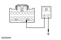 | Yes
GO to AT2 . No REPAIR the circuit. CLEAR the DTCs. REPEAT the self-test. DISCONNECT the battery ground cable. CONNECT passenger seat side air bag C337 and passenger safety belt buckle C3066. CONNECT driver seat side air bag C367 and driver safety belt buckle C3065. REPOWER the SRS . REFER to Section 501-20B . |
| AT2 CHECK THE CUSHION TED BLOWER MOTOR SPEED CONTROL AND BLOWER MOTOR GROUND CIRCUITS FOR A SHORT TOGETHER | |
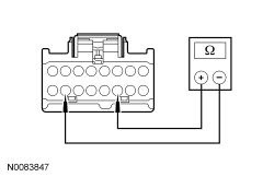 | Yes
INSTALL a new cushion TED . REFER to Seat Cushion Thermo-Electric Device in this section. CLEAR the DTCs. REPEAT the self-test. If the DTC is retrieved again, INSTALL a new DCSM . REFER to Dual Climate Controlled Seat Module (DCSM) in this section. CLEAR the DTCs. REPEAT the self-test. DISCONNECT the battery ground cable. CONNECT passenger seat side air bag C337 and passenger safety belt buckle C3066. CONNECT driver seat side air bag C367 and driver safety belt buckle C3065. REPOWER the SRS . REFER to Section 501-20B . No REPAIR the circuits. CLEAR the DTCs. REPEAT the self-test. DISCONNECT the battery ground cable. CONNECT passenger seat side air bag C337 and passenger safety belt buckle C3066. CONNECT driver seat side air bag C367 and driver safety belt buckle C3065. REPOWER the SRS . REFER to Section 501-20B . |
Pinpoint Test AU: DTC B19A8
Refer to Wiring Diagrams Cell 119 , Climate Controlled Seats for schematic and connector information.
The Dual Climate Controlled Seat Module (DCSM) supplies voltage and ground to the driver seat backrest Thermo-Electric Device (TED). The DCSM also sends a speed control voltage signal to the TED to control blower speed.
NOTICE: When taking measurements at Dual Climate Controlled Seat Module (DCSM) harness connectors, do not insert the electrical probes into the female connector pins. Inserting the probes into connector pins can cause intermittent or open electrical connections after reassembly resulting in Diagnostic Trouble Codes (DTCs) and system failure. Touching the tip of these connector pins is recommended instead.
NOTE: The air bag warning indicator illuminates when the correct Restraints Control Module (RCM) fuse is removed and the ignition switch is on.
NOTE: The Supplemental Restraint System (SRS) must be fully operational and free of faults before releasing the vehicle to the customer.
| Test Step | Result / Action to Take |
|---|---|
| AU1 CHECK THE BACKREST TED BLOWER MOTOR SPEED CONTROL CIRCUIT FOR A SHORT TO GROUND | |
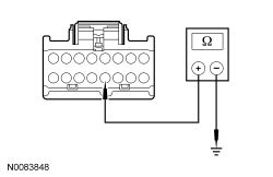 | Yes
GO to AU2 . No REPAIR the circuit. CLEAR the DTCs. REPEAT the self-test. DISCONNECT the battery ground cable. CONNECT passenger seat side air bag C337 and passenger safety belt buckle C3066. CONNECT driver seat side air bag C367 and driver safety belt buckle C3065. REPOWER the SRS . REFER to Section 501-20B . |
| AU2 CHECK THE BACKREST TED BLOWER MOTOR SPEED CONTROL AND BLOWER MOTOR GROUND CIRCUITS FOR A SHORT TOGETHER | |
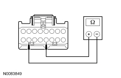 | Yes
INSTALL a new backrest TED . REFER to Seat Backrest Thermo-Electric Device in this section. CLEAR the DTCs. REPEAT the self-test. If the DTC is retrieved again, INSTALL a new DCSM . REFER to Dual Climate Controlled Seat Module (DCSM) in this section. CLEAR the DTCs. REPEAT the self-test. DISCONNECT the battery ground cable. CONNECT passenger seat side air bag C337 and passenger safety belt buckle C3066. CONNECT driver seat side air bag C367 and driver safety belt buckle C3065. REPOWER the SRS . REFER to Section 501-20B . No REPAIR the circuits. CLEAR the DTCs. REPEAT the self-test. DISCONNECT the battery ground cable. CONNECT passenger seat side air bag C337 and passenger safety belt buckle C3066. CONNECT driver seat side air bag C367 and driver safety belt buckle C3065. REPOWER the SRS . REFER to Section 501-20B . |
Pinpoint Test AV: DTC B2486
Refer to Wiring Diagrams Cell 123 , Memory Seats for schematic and connector information.
Refer to Wiring Diagrams Cell 119 , Climate Controlled Seats for schematic and connector information.
The Dual Climate Controlled Seat Module (DCSM) monitors the input voltage for correct operation. If the DCSM detects input voltage below 11 volts or above 15 volts, it will store DTC B2486 in memory. If DTC B2486 is set, the DCSM enters a standby mode and suspends the system outputs for both seat's operation until system voltage between 10 and 15 volts is restored and a climate controlled seat switch button is selected on.
NOTICE: When taking measurements at Dual Climate Controlled Seat Module (DCSM) harness connectors, do not insert the electrical probes into the female connector pins. Inserting the probes into connector pins can cause intermittent or open electrical connections after reassembly resulting in Diagnostic Trouble Codes (DTCs) and system failure. Touching the tip of these connector pins is recommended instead.
NOTE: DTCs B2486 can be set if the vehicle has been recently jump started, the battery has been recently charged or the battery has been discharged. The battery may become discharged due to excessive load(s) on the charging system from aftermarket accessories or if the battery has been left unattended with the accessories on.
NOTE: The air bag warning indicator illuminates when the correct Restraints Control Module (RCM) fuse is removed and the ignition switch is on.
NOTE: The Supplemental Restraint System (SRS) must be fully operational and free of faults before releasing the vehicle to the customer.
| Test Step | Result / Action to Take |
|---|---|
| AV1 RETRIEVE ALL CMDTCs IN ALL MODULES | |
| Yes
REFER to Section 414-00 to diagnose the charging system. No GO to AV2 . |
| AV2 CHECK THE BATTERY CONDITION | |
| Yes
If the battery passed the condition test but required a recharge, REFER to Section 414-00 to diagnose the charging system. CLEAR all Continuous Memory Diagnostic Trouble Codes (CMDTCs). TEST the system for normal operation. If the battery passed the condition test and did not require a recharge, GO to AV3 . No INSTALL a new battery. CLEAR all CMDTCs . TEST the system for normal operation. |
| AV3 CHECK THE CHARGING SYSTEM VOLTAGE | |
NOTE: Do not allow the engine speed to increase above 2,000 rpm while performing this step or the generator may self excite and result in default charging system output voltage. If engine speed goes above 2,000 rpm, shut the vehicle OFF and restart the engine before performing this step. 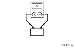 | Yes
GO to AV4 . No REFER to Section 414-00 to diagnose the charging system. CLEAR all CMDTCs . TEST the system for normal operation. |
| AV4 CHECK FOR VOLTAGE TO THE DCSM | |
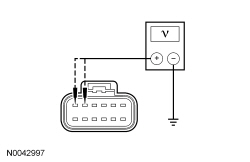 | Yes
GO to AV5 . No REPAIR the circuit in question. CLEAR all CMDTCs . REPEAT the self-test. DISCONNECT the battery ground cable. CONNECT passenger seat side air bag C337 and passenger safety belt buckle C3066. REPOWER the SRS . REFER to Section 501-20B . |
| AV5 CHECK THE DCSM GROUND CIRCUIT FOR AN OPEN | |
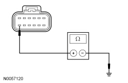 | Yes
GO to AV6 . No REPAIR the circuit. CLEAR all CMDTCs . REPEAT the self-test. DISCONNECT the battery ground cable. CONNECT passenger seat side air bag C337 and passenger safety belt buckle C3066. REPOWER the SRS . REFER to Section 501-20B . |
| AV6 CHECK FOR CORRECT DCSM OPERATION | |
| Yes
INSTALL a new DCSM . REFER to Dual Climate Controlled Seat Module (DCSM) in this section. CLEAR all CMDTCs . REPEAT the self-test. DISCONNECT the battery ground cable. CONNECT passenger seat side air bag C337 and passenger safety belt buckle C3066. REPOWER the SRS . REFER to Section 501-20B . No The system is operating correctly at this time. The concern may have been caused by a loose or corroded connector. CLEAR all CMDTCs . REPEAT the self-test. DISCONNECT the battery ground cable. CONNECT passenger seat side air bag C337 and passenger safety belt buckle C3066. REPOWER the SRS . REFER to Section 501-20B . |
Pinpoint Test AW: DTC B2729
Refer to Wiring Diagrams Cell 119 , Climate Controlled Seats for schematic and connector information.
The Dual Climate Controlled Seat Module (DCSM) monitors seat cushion temperature while it supplies voltage and ground to both blower motors. The DCSM also supplies a variable voltage signal to control the blower speed. Cabin air enters the blower through a filter attached to the Thermo-Electric Device (TED) housing. Heated or cooled air exits the TED and flows through a manifold attached to the foam pad.
NOTICE: When taking measurements at Dual Climate Controlled Seat Module (DCSM) harness connectors, do not insert the electrical probes into the female connector pins. Inserting the probes into connector pins can cause intermittent or open electrical connections after reassembly resulting in Diagnostic Trouble Codes (DTCs) and system failure. Touching the tip of these connector pins is recommended instead.
NOTE: The air bag warning indicator illuminates when the correct Restraints Control Module (RCM) fuse is removed and the ignition is ON.
NOTE: The Supplemental Restraint System (SRS) must be fully operational and free of faults before releasing the vehicle to the customer.
| Test Step | Result / Action to Take | ||||||||||||
|---|---|---|---|---|---|---|---|---|---|---|---|---|---|
| AW1 CHECK THE DCSM FOR ON-DEMAND DTCs | |||||||||||||
| Yes
GO to AW2 . No GO to AW5 . | ||||||||||||
| AW2 CHECK THE DRIVER SEAT CUSHION TED THERMISTOR CIRCUITS FOR A SHORT TO GROUND | |||||||||||||
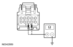 | Yes
GO to AW3 . No REPAIR the circuit(s). CLEAR the DTCs. REPEAT the self-test. DISCONNECT the battery ground cable. CONNECT passenger seat side air bag C337 and passenger safety belt buckle C3066. CONNECT driver seat side air bag C367 and driver safety belt buckle C3065. REPOWER the SRS . REFER to Section 501-20B . | ||||||||||||
| AW3 CHECK THE DRIVER SEAT CUSHION TED THERMISTOR AND WIRING | |||||||||||||
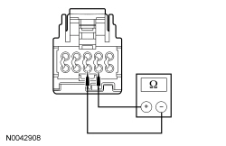 | Yes
GO to AW18 . No GO to AW4 . | ||||||||||||
| AW4 CHECK THE DRIVER SEAT CUSHION TED THERMISTOR | |||||||||||||
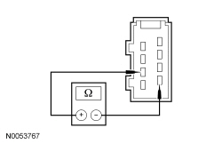 | Yes
REPAIR circuit VHS26 (VT) or RHS05 (YE/VT) for an open or high resistance. CLEAR the DTCs. REPEAT the self-test. DISCONNECT the battery ground cable. CONNECT passenger seat side air bag C337 and passenger safety belt buckle C3066. CONNECT driver seat side air bag C367 and driver safety belt buckle C3065. REPOWER the SRS . REFER to Section 501-20B . No INSTALL a new driver seat cushion TED . REFER to Seat Cushion Thermo-Electric Device in this section. CLEAR the DTCs. REPEAT the self-test. DISCONNECT the battery ground cable. CONNECT passenger seat side air bag C337 and passenger safety belt buckle C3066. CONNECT driver seat side air bag C367 and driver safety belt buckle C3065. REPOWER the SRS . REFER to Section 501-20B . | ||||||||||||
| AW5 CONFIRM THE FAULT WHILE MONITORING THE DCSM SEAT BACK THERMAL ELECTRIC DEVICE TEMPERATURE (BK_TEMP) AND SEAT CUSHION THERMAL ELECTRIC DEVICE TEMPERATURE (CSHTEMP) PIDs | |||||||||||||
| Yes
Fault not present at this time. Fault may have been set due to a past failure, incorrect use of the climate controlled seat system by repeated switching between heat and cool modes or due to excessive passenger compartment temperature. CLEAR the DTCs. REPEAT the self-test. No If the CSHTEMP PID increases incrementally and is greater than 15°C (27°F) of the BK_TEMP PID, GO to AW6 . If the CSHTEMP PID increases quickly (temperature "jumps" and does not increase incrementally) and is greater than 15°C (27°F) of the BK_TEMP PID, GO to AW16 . | ||||||||||||
| AW6 COMPARE OPERATION OF THE DRIVER AND PASSENGER SEATS | |||||||||||||
| Yes
GO to AW7 . No If the airflow exhausting from the driver seat cushion TED is not comparable to the airflow exhausting from the passenger seat cushion TED , GO to AW8 . If the driver seat cushion TED blower operation changed while carrying out the wiggle test, IDENTIFY and REPAIR the wiring fault. CLEAR the DTCs. REPEAT the self-test. | ||||||||||||
| AW7 COMPARE OPERATION OF THE DRIVER AND PASSENGER SEATS WHILE OCCUPIED | |||||||||||||
| Yes
GO to AW16 . No INSTALL a new driver seat cushion foam pad and/or climate controlled seat manifold. CLEAR the DTCs. REPEAT the self-test. | ||||||||||||
| AW8 CHECK THE DRIVER SEAT CUSHION BLOWER FOR AN OBSTRUCTION OR RESTRICTED FILTER | |||||||||||||
| Yes
REMOVE the obstruction or INSTALL a new filter. CLEAR the DTCs. REPEAT the self-test. No GO to AW9 . | ||||||||||||
| AW9 CHECK THE DRIVER SEAT CUSHION BLOWER SPEED CONTROL CIRCUIT FOR AN OPEN | |||||||||||||
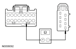 | Yes
GO to AW10 . No REPAIR the circuit. CLEAR the DTCs. REPEAT the self-test. DISCONNECT the battery ground cable. CONNECT passenger seat side air bag C337 and passenger safety belt buckle C3066. CONNECT driver seat side air bag C367 and driver safety belt buckle C3065. REPOWER the SRS . REFER to Section 501-20B . | ||||||||||||
| AW10 CHECK THE DRIVER SEAT CUSHION BLOWER CIRCUIT FOR A SHORT TO VOLTAGE | |||||||||||||
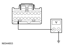 | Yes
REPAIR the circuit. CLEAR the DTCs. REPEAT the self-test. DISCONNECT the battery ground cable. CONNECT passenger seat side air bag C337 and passenger safety belt buckle C3066. CONNECT driver seat side air bag C367 and driver safety belt buckle C3065. REPOWER the SRS . REFER to Section 501-20B . No GO to AW11 . | ||||||||||||
| AW11 CHECK THE DRIVER SEAT CUSHION BLOWER CIRCUIT FOR A SHORT TO GROUND | |||||||||||||
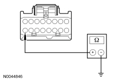 | Yes
GO to AW12 . No REPAIR the circuit. CLEAR the DTCs. REPEAT the self-test. DISCONNECT the battery ground cable. CONNECT passenger seat side air bag C337 and passenger safety belt buckle C3066. CONNECT driver seat side air bag C367 and driver safety belt buckle C3065. REPOWER the SRS . REFER to Section 501-20B . | ||||||||||||
| AW12 CHECK THE DRIVER SEAT CUSHION BLOWER CIRCUITS FOR AN OPEN | |||||||||||||
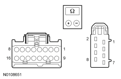 | Yes
GO to AW13 . No REPAIR the circuit(s). CLEAR the DTCs. REPEAT the self-test. DISCONNECT the battery ground cable. CONNECT passenger seat side air bag C337 and passenger safety belt buckle C3066. CONNECT driver seat side air bag C367 and driver safety belt buckle C3065. REPOWER the SRS . REFER to Section 501-20B . | ||||||||||||
| AW13 CHECK THE DRIVER SEAT CUSHION BLOWER RESISTANCE | |||||||||||||
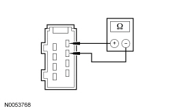 | Yes
GO to AW14 . No INSTALL a new driver seat cushion TED . REFER to Seat Cushion Thermo-Electric Device in this section. CLEAR the DTCs. REPEAT the self-test. DISCONNECT the battery ground cable. CONNECT passenger seat side air bag C337 and passenger safety belt buckle C3066. CONNECT driver seat side air bag C367 and driver safety belt buckle C3065. REPOWER the SRS . REFER to Section 501-20B . | ||||||||||||
| AW14 CHECK THE DRIVER SEAT CUSHION BLOWER SPEED CONTROL RESISTANCE | |||||||||||||
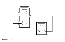 | Yes
GO to AW15 . No INSTALL a new driver seat cushion TED . REFER to Seat Cushion Thermo-Electric Device in this section. CLEAR the DTCs. REPEAT the self-test. DISCONNECT the battery ground cable. CONNECT passenger seat side air bag C337 and passenger safety belt buckle C3066. CONNECT driver seat side air bag C367 and driver safety belt buckle C3065. REPOWER the SRS . REFER to Section 501-20B . | ||||||||||||
| AW15 CHECK THE DRIVER SEAT CUSHION TED INSTALLATION AND FOR CRUSHED SEAT CUSHION | |||||||||||||
| Yes
INSTALL the driver seat cushion cover and seat and GO to AW18 . No CORRECTLY install the driver seat cushion TED or INSTALL a new driver seat cushion foam pad and/or climate controlled seat manifold. CONNECT the battery ground cable. REFER to Section 414-01 . CLEAR the DTCs. REPEAT the self-test. DISCONNECT the battery ground cable. CONNECT passenger seat side air bag C337 and passenger safety belt buckle C3066. CONNECT driver seat side air bag C367 and driver safety belt buckle C3065. REPOWER the SRS . REFER to Section 501-20B . | ||||||||||||
| AW16 CHECK THE DRIVER SEAT CUSHION TED THERMISTOR AND WIRING | |||||||||||||
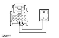 | Yes
GO to AW18 . No GO to AW17 . | ||||||||||||
| AW17 CHECK THE DRIVER SEAT CUSHION TED THERMISTOR | |||||||||||||
 | Yes
REPAIR circuit VHS26 (VT) or RHS05 (YE/VT) for an open or high resistance. CLEAR the DTCs. REPEAT the self-test. DISCONNECT the battery ground cable. CONNECT passenger seat side air bag C337 and passenger safety belt buckle C3066. CONNECT driver seat side air bag C367 and driver safety belt buckle C3065. REPOWER the SRS . REFER to Section 501-20B . No INSTALL a new TED . REFER to Seat Cushion Thermo-Electric Device in this section. CLEAR the DTCs. REPEAT the self-test. DISCONNECT the battery ground cable. CONNECT passenger seat side air bag C337 and passenger safety belt buckle C3066. CONNECT driver seat side air bag C367 and driver safety belt buckle C3065. REPOWER the SRS . REFER to Section 501-20B . | ||||||||||||
| AW18 CHECK THE DRIVER SEAT CUSHION TED HEATING/COOLING CIRCUITRY CURRENT DRAW | |||||||||||||
| Yes
GO to AW19 . No INSTALL a new driver seat cushion TED . REFER to Seat Cushion Thermo-Electric Device in this section. CLEAR the DTCs. REPEAT the self-test. DISCONNECT the battery ground cable. CONNECT passenger seat side air bag C337 and passenger safety belt buckle C3066. CONNECT driver seat side air bag C367 and driver safety belt buckle C3065. REPOWER the SRS . REFER to Section 501-20B . | ||||||||||||
| AW19 CHECK RESISTANCE OF THE DRIVER SEAT CUSHION TED AND WIRING | |||||||||||||
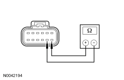 | Yes
GO to AW21 . No GO to AW20 . | ||||||||||||
| AW20 CHECK THE RESISTANCE OF THE DRIVER SEAT CUSHION TED | |||||||||||||
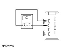 | Yes
REPAIR circuit CHS02 (YE/BU) or RHS02 (BU/OG) for an open or high resistance. CLEAR the DTCs. REPEAT the self-test. DISCONNECT the battery ground cable. CONNECT passenger seat side air bag C337 and passenger safety belt buckle C3066. CONNECT driver seat side air bag C367 and driver safety belt buckle C3065. REPOWER the SRS . REFER to Section 501-20B . No INSTALL a new driver seat cushion TED . REFER to Seat Cushion Thermo-Electric Device in this section. CLEAR the DTCs. REPEAT the self-test. DISCONNECT the battery ground cable. CONNECT passenger seat side air bag C337 and passenger safety belt buckle C3066. CONNECT driver seat side air bag C367 and driver safety belt buckle C3065. REPOWER the SRS . REFER to Section 501-20B . | ||||||||||||
| AW21 CHECK FOR CORRECT DCSM OPERATION | |||||||||||||
| Yes
INSTALL a new DCSM . REFER to Dual Climate Controlled Seat Module (DCSM) in this section. REPEAT the self-test. TEST the system for normal operation. DISCONNECT the battery ground cable. CONNECT passenger seat side air bag C337 and passenger safety belt buckle C3066. CONNECT driver seat side air bag C367 and driver safety belt buckle C3065. REPOWER the SRS . REFER to Section 501-20B . No The system is operating correctly at this time. The concern may have been caused by a loose or corroded connector. DISCONNECT the battery ground cable. CONNECT passenger seat side air bag C337 and passenger safety belt buckle C3066. CONNECT driver seat side air bag C367 and driver safety belt buckle C3065. REPOWER the SRS . REFER to Section 501-20B . |
Pinpoint Test AX: DTC B272A
Refer to Wiring Diagrams Cell 119 , Climate Controlled Seats for schematic and connector information.
The Dual Climate Controlled Seat Module (DCSM) monitors seat cushion temperature while it supplies voltage and ground to both blower motors. The DCSM also supplies a variable voltage signal to control the blower speed. Cabin air enters the blower through a filter attached to the Thermo-Electric Device (TED) housing. Heated or cooled air exits the TED and flows through a manifold attached to the foam pad.
NOTICE: When taking measurements at Dual Climate Controlled Seat Module (DCSM) harness connectors, do not insert the electrical probes into the female connector pins. Inserting the probes into connector pins can cause intermittent or open electrical connections after reassembly resulting in Diagnostic Trouble Codes (DTCs) and system failure. Touching the tip of these connector pins is recommended instead.
NOTE: The air bag warning indicator illuminates when the correct Restraints Control Module (RCM) fuse is removed and the ignition is ON.
NOTE: The Supplemental Restraint System (SRS) must be fully operational and free of faults before releasing the vehicle to the customer.
| Test Step | Result / Action to Take | ||||||||||||
|---|---|---|---|---|---|---|---|---|---|---|---|---|---|
| AX1 CHECK THE DCSM FOR ON-DEMAND DTCs | |||||||||||||
| Yes
GO to AX2 . No GO to AX5 . | ||||||||||||
| AX2 CHECK THE PASSENGER SEAT CUSHION TED THERMISTOR CIRCUITS FOR A SHORT TO GROUND | |||||||||||||
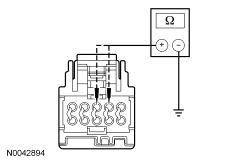 | Yes
GO to AX3 . No REPAIR the circuit(s). CLEAR the DTCs. REPEAT the self-test. DISCONNECT the battery ground cable. CONNECT passenger seat side air bag C337 and passenger safety belt buckle C3066. REPOWER the SRS . REFER to Section 501-20B . | ||||||||||||
| AX3 CHECK THE PASSENGER SEAT CUSHION TED THERMISTOR AND WIRING | |||||||||||||
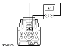 | Yes
GO to AX18 . No GO to AX4 . | ||||||||||||
| AX4 CHECK THE PASSENGER SEAT CUSHION TED THERMISTOR | |||||||||||||
 | Yes
REPAIR circuit VHS27 (WH/OG) or RHS10 (BU/OG) for an open or high resistance. CLEAR the DTCs. REPEAT the self-test. DISCONNECT the battery ground cable. CONNECT passenger seat side air bag C337 and passenger safety belt buckle C3066. REPOWER the SRS . REFER to Section 501-20B . No INSTALL a new passenger seat cushion TED . REFER to Seat Cushion Thermo-Electric Device in this section. CLEAR the DTCs. REPEAT the self-test. DISCONNECT the battery ground cable. CONNECT passenger seat side air bag C337 and passenger safety belt buckle C3066. REPOWER the SRS . REFER to Section 501-20B . | ||||||||||||
| AX5 CONFIRM THE FAULT WHILE MONITORING THE DCSM SEAT BACK THERMAL ELECTRIC DEVICE TEMPERATURE (PBKTEMP) AND SEAT CUSHION THERMAL ELECTRIC DEVICE TEMPERATURE (PCSHTEMP) PIDs | |||||||||||||
| Yes
Fault not present at this time. Fault may have been set due to a past failure, incorrect use of the climate controlled seat system by repeated switching between heat and cool modes or due to excessive passenger compartment temperature. CLEAR the DTCs. REPEAT the self-test. No If the PCSHTEMP PID increases incrementally and is greater than 15°C (27°F) of the PBKTEMP PID, GO to AX6 . If the PCSHTEMP PID increases quickly (temperature "jumps" and does not increase incrementally) and is greater than 15°C (27°F) of the PBKTEMP PID, GO to AX16 . | ||||||||||||
| AX6 COMPARE OPERATION OF THE DRIVER AND PASSENGER SEATS | |||||||||||||
| Yes
GO to AX7 . No If the airflow exhausting from the passenger seat cushion TED is not comparable to the airflow exhausting from the driver seat cushion TED , GO to AX8 . If the passenger seat cushion TED blower operation changed while carrying out the wiggle test, IDENTIFY and REPAIR the wiring fault. CLEAR the DTCs. REPEAT the self-test. | ||||||||||||
| AX7 COMPARE OPERATION OF THE DRIVER AND PASSENGER SEATS WHILE OCCUPIED | |||||||||||||
| Yes
GO to AX16 . No INSTALL a new passenger seat cushion foam pad and/or climate controlled seat manifold. CLEAR the DTCs. REPEAT the self-test. | ||||||||||||
| AX8 CHECK THE PASSENGER SEAT CUSHION BLOWER FOR AN OBSTRUCTION OR RESTRICTED FILTER | |||||||||||||
| Yes
REMOVE the obstruction or INSTALL a new filter. CLEAR the DTCs. REPEAT the self-test. No GO to AX9 . | ||||||||||||
| AX9 CHECK THE PASSENGER SEAT CUSHION BLOWER SPEED CONTROL CIRCUIT FOR AN OPEN | |||||||||||||
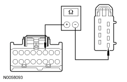 | Yes
GO to AX10 . No REPAIR the circuit. CLEAR the DTCs. REPEAT the self-test. DISCONNECT the battery ground cable. CONNECT passenger seat side air bag C337 and passenger safety belt buckle C3066. REPOWER the SRS . REFER to Section 501-20B . | ||||||||||||
| AX10 CHECK THE PASSENGER SEAT CUSHION BLOWER CIRCUIT FOR A SHORT TO VOLTAGE | |||||||||||||
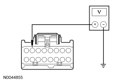 | Yes
REPAIR the circuit. CLEAR the DTCs. REPEAT the self-test. DISCONNECT the battery ground cable. CONNECT passenger seat side air bag C337 and passenger safety belt buckle C3066. REPOWER the SRS . REFER to Section 501-20B . No GO to AX11 . | ||||||||||||
| AX11 CHECK THE PASSENGER SEAT CUSHION BLOWER CIRCUIT FOR A SHORT TO GROUND | |||||||||||||
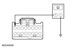 | Yes
GO to AX12 . No REPAIR the circuit. CLEAR the DTCs. REPEAT the self-test. DISCONNECT the battery ground cable. CONNECT passenger seat side air bag C337 and passenger safety belt buckle C3066. REPOWER the SRS . REFER to Section 501-20B . | ||||||||||||
| AX12 CHECK THE PASSENGER SEAT CUSHION BLOWER CIRCUITS FOR AN OPEN | |||||||||||||
 | Yes
GO to AX13 . No REPAIR the circuit(s). CLEAR the DTCs. REPEAT the self-test. DISCONNECT the battery ground cable. CONNECT passenger seat side air bag C337 and passenger safety belt buckle C3066. REPOWER the SRS . REFER to Section 501-20B . | ||||||||||||
| AX13 CHECK THE PASSENGER SEAT CUSHION BLOWER RESISTANCE | |||||||||||||
 | Yes
GO to AX14 . No INSTALL a new passenger seat cushion TED . REFER to Seat Cushion Thermo-Electric Device in this section. CLEAR the DTCs. REPEAT the self-test. DISCONNECT the battery ground cable. CONNECT passenger seat side air bag C337 and passenger safety belt buckle C3066. REPOWER the SRS . REFER to Section 501-20B . | ||||||||||||
| AX14 CHECK THE PASSENGER SEAT CUSHION BLOWER SPEED CONTROL RESISTANCE | |||||||||||||
 | Yes
GO to AX15 . No INSTALL a new passenger seat cushion TED . REFER to Seat Cushion Thermo-Electric Device in this section. CLEAR the DTCs. REPEAT the self-test. DISCONNECT the battery ground cable. CONNECT passenger seat side air bag C337 and passenger safety belt buckle C3066. REPOWER the SRS . REFER to Section 501-20B . | ||||||||||||
| AX15 CHECK THE PASSENGER SEAT CUSHION TED INSTALLATION AND FOR CRUSHED SEAT CUSHION | |||||||||||||
| Yes
INSTALL the passenger seat cushion cover and seat and GO to AX18 . No CORRECTLY install the passenger seat cushion TED or INSTALL a new passenger seat cushion foam pad and/or climate controlled seat manifold. CONNECT the battery ground cable. REFER to Section 414-01 . CLEAR the DTCs. REPEAT the self-test. DISCONNECT the battery ground cable. CONNECT passenger seat side air bag C337 and passenger safety belt buckle C3066. REPOWER the SRS . REFER to Section 501-20B . | ||||||||||||
| AX16 CHECK THE PASSENGER SEAT CUSHION TED THERMISTOR AND WIRING | |||||||||||||
 | Yes
GO to AX18 . No GO to AX17 . | ||||||||||||
| AX17 CHECK THE PASSENGER SEAT CUSHION TED THERMISTOR | |||||||||||||
 | Yes
REPAIR circuit VHS27 (WH/OG) or RHS10 (BU/OG) for an open or high resistance. CLEAR the DTCs. REPEAT the self-test. DISCONNECT the battery ground cable. CONNECT passenger seat side air bag C337 and passenger safety belt buckle C3066. REPOWER the SRS . REFER to Section 501-20B . No INSTALL a new TED . REFER to Seat Cushion Thermo-Electric Device in this section. CLEAR the DTCs. REPEAT the self-test. DISCONNECT the battery ground cable. CONNECT passenger seat side air bag C337 and passenger safety belt buckle C3066. REPOWER the SRS . REFER to Section 501-20B . | ||||||||||||
| AX18 CHECK THE PASSENGER SEAT CUSHION TED HEATING/COOLING CIRCUITRY CURRENT DRAW | |||||||||||||
| Yes
GO to AX19 . No INSTALL a new passenger seat cushion TED . REFER to Seat Cushion Thermo-Electric Device in this section. CLEAR the DTCs. REPEAT the self-test. DISCONNECT the battery ground cable. CONNECT passenger seat side air bag C337 and passenger safety belt buckle C3066. REPOWER the SRS . REFER to Section 501-20B . | ||||||||||||
| AX19 CHECK RESISTANCE OF THE PASSENGER SEAT CUSHION TED AND WIRING | |||||||||||||
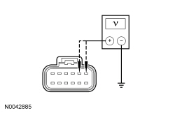 | Yes
GO to AX21 . No GO to AX20 . | ||||||||||||
| AX20 CHECK THE RESISTANCE OF THE PASSENGER SEAT CUSHION TED | |||||||||||||
 | Yes
REPAIR circuit CHS07 (GY/BU) or RHS07 (BU) for an open or high resistance. CLEAR the DTCs. REPEAT the self-test. DISCONNECT the battery ground cable. CONNECT passenger seat side air bag C337 and passenger safety belt buckle C3066. REPOWER the SRS . REFER to Section 501-20B . No INSTALL a new passenger seat cushion TED . REFER to Seat Cushion Thermo-Electric Device in this section. CLEAR the DTCs. REPEAT the self-test. DISCONNECT the battery ground cable. CONNECT passenger seat side air bag C337 and passenger safety belt buckle C3066. REPOWER the SRS . REFER to Section 501-20B . | ||||||||||||
| AX21 CHECK FOR CORRECT DCSM OPERATION | |||||||||||||
| Yes
INSTALL a new DCSM . REFER to Dual Climate Controlled Seat Module (DCSM) in this section. REPEAT the self-test. TEST the system for normal operation. DISCONNECT the battery ground cable. CONNECT passenger seat side air bag C337 and passenger safety belt buckle C3066. REPOWER the SRS . REFER to Section 501-20B . No The system is operating correctly at this time. The concern may have been caused by a loose or corroded connector. DISCONNECT the battery ground cable. CONNECT passenger seat side air bag C337 and passenger safety belt buckle C3066. REPOWER the SRS . REFER to Section 501-20B . |
Pinpoint Test AY: DTC B272B
Refer to Wiring Diagrams Cell 119 , Climate Controlled Seats for schematic and connector information.
The Dual Climate Controlled Seat Module (DCSM) monitors seat backrest temperature while it supplies voltage and ground to both blower motors. The DCSM also supplies a variable voltage signal to control the blower speed. Cabin air enters the blower through a filter attached to the Thermo-Electric Device (TED) housing. Heated or cooled air exits the TED and flows through a manifold attached to the foam pad.
NOTICE: When taking measurements at Dual Climate Controlled Seat Module (DCSM) harness connectors, do not insert the electrical probes into the female connector pins. Inserting the probes into connector pins can cause intermittent or open electrical connections after reassembly resulting in Diagnostic Trouble Codes (DTCs) and system failure. Touching the tip of these connector pins is recommended instead.
NOTE: The air bag warning indicator illuminates when the correct Restraints Control Module (RCM) fuse is removed and the ignition is ON.
NOTE: The Supplemental Restraint System (SRS) must be fully operational and free of faults before releasing the vehicle to the customer.
| Test Step | Result / Action to Take | ||||||||||||
|---|---|---|---|---|---|---|---|---|---|---|---|---|---|
| AY1 CHECK THE DCSM FOR ON-DEMAND DTCs | |||||||||||||
| Yes
GO to AY2 . No GO to AY5 . | ||||||||||||
| AY2 CHECK THE PASSENGER SEAT BACKREST TED THERMISTOR CIRCUITS FOR A SHORT TO GROUND | |||||||||||||
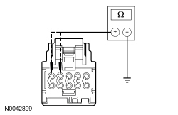 | Yes
GO to AY3 . No REPAIR the circuit(s). CLEAR the DTCs. REPEAT the self-test. DISCONNECT the battery ground cable. CONNECT passenger seat side air bag C337 and passenger safety belt buckle C3066. REPOWER the SRS . REFER to Section 501-20B . | ||||||||||||
| AY3 CHECK THE PASSENGER SEAT BACKREST TED THERMISTOR AND WIRING | |||||||||||||
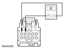 | Yes
GO to AY18 . No GO to AY4 . | ||||||||||||
| AY4 CHECK THE PASSENGER SEAT BACKREST TED THERMISTOR | |||||||||||||
 | Yes
REPAIR circuit VHS36 (YE/BU) or RHS20 (GN/BU) for an open or high resistance. CLEAR the DTCs. REPEAT the self-test. DISCONNECT the battery ground cable. CONNECT passenger seat side air bag C337 and passenger safety belt buckle C3066. REPOWER the SRS . REFER to Section 501-20B . No INSTALL a new passenger seat backrest TED . REFER to Seat Backrest Thermo-Electric Device in this section. CLEAR the DTCs. REPEAT the self-test. DISCONNECT the battery ground cable. CONNECT passenger seat side air bag C337 and passenger safety belt buckle C3066. REPOWER the SRS . REFER to Section 501-20B . | ||||||||||||
| AY5 CONFIRM THE FAULT WHILE MONITORING THE DCSM SEAT BACK THERMAL ELECTRIC DEVICE TEMPERATURE (PBKTEMP) AND SEAT CUSHION THERMAL ELECTRIC DEVICE TEMPERATURE (PCSHTEMP) PIDs | |||||||||||||
| Yes
Fault not present at this time. Fault may have been set due to a past failure, incorrect use of the climate controlled seat system by repeated switching between heat and cool modes or due to excessive passenger compartment temperature. CLEAR the DTCs. REPEAT the self-test. No If the PBKTEMP PID increases incrementally and is greater than 15°C (27°F) of the PCSHTEMP PID, GO to AY6 . If the PBKTEMP PID increases quickly (temperature "jumps" and does not increase incrementally) and is greater than 15°C (27°F) of the PCSHTEMP PID, GO to AY16 . | ||||||||||||
| AY6 COMPARE OPERATION OF THE DRIVER AND PASSENGER SEATS | |||||||||||||
| Yes
GO to AY7 . No If the airflow exhausting from the passenger seat backrest TED is not comparable to the airflow exhausting from the driver seat backrest TED , GO to AY8 . If the passenger seat backrest TED blower operation changed while carrying out the wiggle test, IDENTIFY and REPAIR the wiring fault. CLEAR the DTCs. REPEAT the self-test. | ||||||||||||
| AY7 COMPARE OPERATION OF THE DRIVER AND PASSENGER SEATS WHILE OCCUPIED | |||||||||||||
| Yes
GO to AY16 . No INSTALL a new passenger seat backrest foam pad and/or climate controlled seat manifold. CLEAR the DTCs. REPEAT the self-test. | ||||||||||||
| AY8 CHECK THE PASSENGER SEAT BACKREST BLOWER FOR AN OBSTRUCTION OR RESTRICTED FILTER | |||||||||||||
| Yes
REMOVE the obstruction or INSTALL a new filter. CLEAR the DTCs. REPEAT the self-test. No GO to AY9 . | ||||||||||||
| AY9 CHECK THE PASSENGER SEAT BACKREST BLOWER SPEED CONTROL CIRCUIT FOR AN OPEN | |||||||||||||
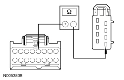 | Yes
GO to AY10 . No REPAIR the circuit. CLEAR the DTCs. REPEAT the self-test. DISCONNECT the battery ground cable. CONNECT passenger seat side air bag C337 and passenger safety belt buckle C3066. REPOWER the SRS . REFER to Section 501-20B . | ||||||||||||
| AY10 CHECK THE PASSENGER SEAT BACKREST BLOWER CIRCUIT FOR A SHORT TO VOLTAGE | |||||||||||||
 | Yes
REPAIR the circuit. CLEAR the DTCs. REPEAT the self-test. DISCONNECT the battery ground cable. CONNECT passenger seat side air bag C337 and passenger safety belt buckle C3066. REPOWER the SRS . REFER to Section 501-20B . No GO to AY11 . | ||||||||||||
| AY11 CHECK THE PASSENGER SEAT BACKREST BLOWER CIRCUIT FOR A SHORT TO GROUND | |||||||||||||
 | Yes
GO to AY12 . No REPAIR the circuit. CLEAR the DTCs. REPEAT the self-test. DISCONNECT the battery ground cable. CONNECT passenger seat side air bag C337 and passenger safety belt buckle C3066. REPOWER the SRS . REFER to Section 501-20B . | ||||||||||||
| AY12 CHECK THE PASSENGER SEAT BACKREST BLOWER CIRCUITS FOR AN OPEN | |||||||||||||
 | Yes
GO to AY13 . No REPAIR the circuit(s). CLEAR the DTCs. REPEAT the self-test. DISCONNECT the battery ground cable. CONNECT passenger seat side air bag C337 and passenger safety belt buckle C3066. REPOWER the SRS . REFER to Section 501-20B . | ||||||||||||
| AY13 CHECK THE PASSENGER SEAT BACKREST BLOWER RESISTANCE | |||||||||||||
 | Yes
GO to AY14 . No INSTALL a new passenger seat backrest TED . REFER to Seat Backrest Thermo-Electric Device in this section. CLEAR the DTCs. REPEAT the self-test. DISCONNECT the battery ground cable. CONNECT passenger seat side air bag C337 and passenger safety belt buckle C3066. REPOWER the SRS . REFER to Section 501-20B . | ||||||||||||
| AY14 CHECK THE PASSENGER SEAT BACKREST BLOWER SPEED CONTROL RESISTANCE | |||||||||||||
 | Yes
GO to AY15 . No INSTALL a new passenger seat backrest TED . REFER to Seat Backrest Thermo-Electric Device in this section. CLEAR the DTCs. REPEAT the self-test. DISCONNECT the battery ground cable. CONNECT passenger seat side air bag C337 and passenger safety belt buckle C3066. REPOWER the SRS . REFER to Section 501-20B . | ||||||||||||
| AY15 CHECK THE PASSENGER SEAT BACKREST TED INSTALLATION AND FOR CRUSHED SEAT BACKREST | |||||||||||||
| Yes
INSTALL the passenger seat backrest cover and seat and GO to AY18 . No CORRECTLY install the passenger seat backrest TED or INSTALL a new passenger seat backrest foam pad and/or climate controlled seat manifold. CONNECT the battery ground cable. REFER to Section 414-01 . CLEAR the DTCs. REPEAT the self-test. DISCONNECT the battery ground cable. CONNECT passenger seat side air bag C337 and passenger safety belt buckle C3066. REPOWER the SRS . REFER to Section 501-20B . | ||||||||||||
| AY16 CHECK THE PASSENGER SEAT BACKREST TED THERMISTOR AND WIRING | |||||||||||||
 | Yes
GO to AY18 . No GO to AY17 . | ||||||||||||
| AY17 CHECK THE PASSENGER SEAT BACKREST TED THERMISTOR | |||||||||||||
 | Yes
REPAIR circuit VHS35 (VT/OG) or RHS15 (GY/BN) for an open or high resistance. CLEAR the DTCs. REPEAT the self-test. DISCONNECT the battery ground cable. CONNECT passenger seat side air bag C337 and passenger safety belt buckle C3066. REPOWER the SRS . REFER to Section 501-20B . No INSTALL a new TED . REFER to Seat Backrest Thermo-Electric Device in this section. CLEAR the DTCs. REPEAT the self-test. DISCONNECT the battery ground cable. CONNECT passenger seat side air bag C337 and passenger safety belt buckle C3066. REPOWER the SRS . REFER to Section 501-20B . | ||||||||||||
| AY18 CHECK THE PASSENGER SEAT BACKREST TED HEATING/COOLING CIRCUITRY CURRENT DRAW | |||||||||||||
| Yes
GO to AY19 . No INSTALL a new passenger seat backrest TED . REFER to Seat Backrest Thermo-Electric Device in this section. CLEAR the DTCs. REPEAT the self-test. DISCONNECT the battery ground cable. CONNECT passenger seat side air bag C337 and passenger safety belt buckle C3066. REPOWER the SRS . REFER to Section 501-20B . | ||||||||||||
| AY19 CHECK RESISTANCE OF THE PASSENGER SEAT BACKREST TED AND WIRING | |||||||||||||
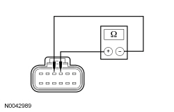 | Yes
GO to AY21 . No GO to AY20 . | ||||||||||||
| AY20 CHECK THE RESISTANCE OF THE PASSENGER SEAT BACKREST TED | |||||||||||||
 | Yes
REPAIR circuit CHS01 (GY/VT) or RHS01 (WH/VT) for an open or high resistance. CLEAR the DTCs. REPEAT the self-test. DISCONNECT the battery ground cable. CONNECT passenger seat side air bag C337 and passenger safety belt buckle C3066. REPOWER the SRS . REFER to Section 501-20B . No INSTALL a new passenger seat backrest TED . REFER to Seat Backrest Thermo-Electric Device in this section. CLEAR the DTCs. REPEAT the self-test. DISCONNECT the battery ground cable. CONNECT passenger seat side air bag C337 and passenger safety belt buckle C3066. REPOWER the SRS . REFER to Section 501-20B . | ||||||||||||
| AY21 CHECK FOR CORRECT DCSM OPERATION | |||||||||||||
| Yes
INSTALL a new DCSM . REFER to Dual Climate Controlled Seat Module (DCSM) in this section. REPEAT the self-test. TEST the system for normal operation. DISCONNECT the battery ground cable. CONNECT passenger seat side air bag C337 and passenger safety belt buckle C3066. REPOWER the SRS . REFER to Section 501-20B . No The system is operating correctly at this time. The concern may have been caused by a loose or corroded connector. DISCONNECT the battery ground cable. CONNECT passenger seat side air bag C337 and passenger safety belt buckle C3066. REPOWER the SRS . REFER to Section 501-20B . |
Pinpoint Test AZ: DTC B272C
Refer to Wiring Diagrams Cell 119 , Climate Controlled Seats for schematic and connector information.
The Dual Climate Controlled Seat Module (DCSM) is supplied voltage at all times, but the climate controlled seat system only operates with the engine running. The system can be operated with the ignition ON engine OFF by using a scan tool to bypass the climate controlled seat buttons on the touchscreen interface. When commanding a heat or cool mode operation in this manner, the climate controlled seat system only operates in 15 second intervals. Both voltage supply circuits are spliced together internal to the DCSM , so if one circuit becomes open, both seats can still be operated. However, if a fault occurs setting a DTC specific to either climate controlled seat, only the affected seat is disabled by the DCSM .
The seat cushion is equipped with a Thermo-Electric Device (TED) assembly that includes a seat blower (fan motor, serviced as an assembly with the TED ). Similarly, the seat backrest is also equipped with its own TED assembly with blower. Cabin air is drawn through the blower and distributed to each of the TED modules located in the seat cushion and backrest. The TEDs then heat or cool the air. The air is then directed into the foam pad and manifold where it is distributed along the surface of the cushion and backrest of the seat. Once the system is activated, the DCSM uses a set of flexible algorithms to control the heating/cooling modes and the blower speed dependant on the commanded climate controlled seat settings.
A differential fault occurs when the cushion and backrest TEDs on an affected seat are reporting very different temperatures to the DCSM . This may result from an air flow restriction or a circuit fault of either TED area. If a TED and manifold is clear of obstruction and is operational, check the other TED and circuitry on the seat. It is important to note that a TED with a higher temperature may be operating correctly and not the area of concern. The other TED may be indicating a much lower temperature, causing the DTC to set.
NOTICE: When taking measurements at Dual Climate Controlled Seat Module (DCSM) harness connectors, do not insert the electrical probes into the female connector pins. Inserting the probes into connector pins can cause intermittent or open electrical connections after reassembly resulting in Diagnostic Trouble Codes (DTCs) and system failure. Touching the tip of these connector pins is recommended instead.
NOTE: The air bag warning indicator illuminates when the correct Restraints Control Module (RCM) fuse is removed and the ignition switch is on.
NOTE: The Supplemental Restraint System (SRS) must be fully operational and free of faults before releasing the vehicle to the customer.
| Test Step | Result / Action to Take | ||||||||||||
|---|---|---|---|---|---|---|---|---|---|---|---|---|---|
| AZ1 CHECK FOR DCSM DTCs | |||||||||||||
| Yes
For DTC B2729, GO to Pinpoint Test AW . For DTC B2730, GO to Pinpoint Test BD . No GO to AZ2 . | ||||||||||||
| AZ2 MONITOR THE TED TEMPERATURE PIDs | |||||||||||||
| Yes
GO to AZ3 . No If the driver seat cushion PID varies 10°C (18°F) or more from ambient temperature, GO to AZ16 . If the driver seat backrest PID varies 10°C (18°F) or more from ambient temperature, GO to AZ32 . | ||||||||||||
| AZ3 CONFIRM THE FAULT IS IN THE SEAT CUSHION OR THE BACKREST | |||||||||||||
| Yes
If the driver seat cushion PID is 60°C (108°F) hotter than the backrest PID, GO to AZ5 . If the driver seat backrest PID is 60°C (108°F) hotter than the cushion PID, GO to AZ20 . No GO to AZ4 . | ||||||||||||
| AZ4 CHECK THE TEDs COOLING PERFORMANCE | |||||||||||||
| Yes
The DTC may have been set by extreme cabin temperatures or excessive sunload on the seat causing the system to enter recovery mode. Occupant size and weight characteristics can also be a factor. CLEAR the DTCs. REPEAT the self-test. If a concern cannot be found or duplicated, RETURN the vehicle to the customer. No CHECK the affected seat cushion or backrest for correct installation of the climate controlled seat components ( TED , manifold, plenum, air ducts and foam pad). CHECK for airflow restrictions ( TED inlets and outlets, TED -to-manifold or plenum connections, filters and ducts) and REPAIR as needed. CHECK for an intermittent wiring fault. REPAIR as needed. CLEAR the DTCs. REPEAT the self-test. TEST the system for normal operation. | ||||||||||||
| AZ5 CHECK FOR CORRECT TED INSTALLATION AND FOR CRUSHED FOAM | |||||||||||||
| Yes
GO to AZ6 . No CORRECTLY install the cushion TED or INSTALL a new seat cushion foam pad and/or climate controlled seat manifold. CLEAR the DTCs. REPEAT the self-test. TEST the system for normal operation. DISCONNECT the battery ground cable. REPOWER the SRS . REFER to Section 501-20B . | ||||||||||||
| AZ6 CHECK THE BACKREST TED GROUND CIRCUIT FOR A SHORT TO VOLTAGE | |||||||||||||
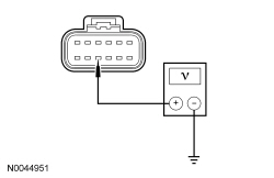 | Yes
REPAIR the circuit. CLEAR the DTCs. REPEAT the self-test. DISCONNECT the battery ground cable. CONNECT passenger seat side air bag C337 and passenger safety belt buckle C3066. CONNECT driver seat side air bag C367 and driver safety belt buckle C3065. REPOWER the SRS . REFER to Section 501-20B . No GO to AZ7 . | ||||||||||||
| AZ7 CHECK THE BACKREST TED FEED CIRCUIT FOR A SHORT TO GROUND | |||||||||||||
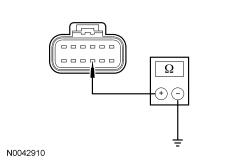 | Yes
GO to AZ8 . No REPAIR the circuit. CLEAR the DTCs. REPEAT the self-test. DISCONNECT the battery ground cable. CONNECT passenger seat side air bag C337 and passenger safety belt buckle C3066. CONNECT driver seat side air bag C367 and driver safety belt buckle C3065. REPOWER the SRS . REFER to Section 501-20B . | ||||||||||||
| AZ8 CHECK THE RESISTANCE OF THE BACKREST TED AND WIRING | |||||||||||||
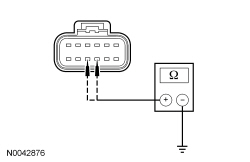 | Yes
GO to AZ10 . No GO to AZ9 . | ||||||||||||
| AZ9 CHECK THE RESISTANCE OF THE BACKREST TED | |||||||||||||
 | Yes
REPAIR the circuit(s). CLEAR the DTCs. REPEAT the self-test. DISCONNECT the battery ground cable. CONNECT passenger seat side air bag C337 and passenger safety belt buckle C3066. CONNECT driver seat side air bag C367 and driver safety belt buckle C3065. REPOWER the SRS . REFER to Section 501-20B . No INSTALL a new backrest TED . REFER to Seat Backrest Thermo-Electric Device in this section. CLEAR the DTCs. REPEAT the self-test. DISCONNECT the battery ground cable. CONNECT passenger seat side air bag C337 and passenger safety belt buckle C3066. CONNECT driver seat side air bag C367 and driver safety belt buckle C3065. REPOWER the SRS . REFER to Section 501-20B . | ||||||||||||
| AZ10 CHECK THE BLOWER MOTOR FEED AND SPEED CONTROL CIRCUITS FOR A SHORT TO VOLTAGE | |||||||||||||
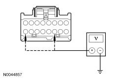 | Yes
GO to AZ11 . No REPAIR the circuit(s). CLEAR the DTCs. REPEAT the self-test. DISCONNECT the battery ground cable. CONNECT passenger seat side air bag C337 and passenger safety belt buckle C3066. CONNECT driver seat side air bag C367 and driver safety belt buckle C3065. REPOWER the SRS . REFER to Section 501-20B . | ||||||||||||
| AZ11 CHECK THE BLOWER MOTOR FEED AND SPEED CONTROL CIRCUITS FOR A SHORT TO GROUND | |||||||||||||
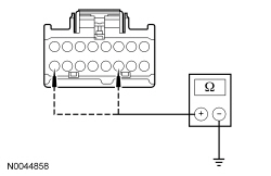 | Yes
GO to AZ12 . No REPAIR the circuit(s). CLEAR the DTCs. REPEAT the self-test. DISCONNECT the battery ground cable. CONNECT passenger seat side air bag C337 and passenger safety belt buckle C3066. CONNECT driver seat side air bag C367 and driver safety belt buckle C3065. REPOWER the SRS . REFER to Section 501-20B . | ||||||||||||
| AZ12 CHECK THE BLOWER MOTOR AND WIRING | |||||||||||||
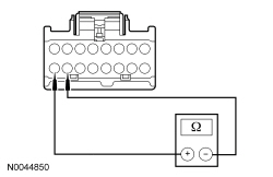 | Yes
GO to AZ14 . No GO to AZ13 . | ||||||||||||
| AZ13 CHECK THE BLOWER MOTOR RESISTANCE | |||||||||||||
 | Yes
REPAIR the circuit(s). CLEAR the DTCs. REPEAT the self-test. DISCONNECT the battery ground cable. CONNECT passenger seat side air bag C337 and passenger safety belt buckle C3066. CONNECT driver seat side air bag C367 and driver safety belt buckle C3065. REPOWER the SRS . REFER to Section 501-20B . No INSTALL a new cushion TED . REFER to Seat Cushion Thermo-Electric Device in this section. CLEAR the DTCs. REPEAT the self-test. DISCONNECT the battery ground cable. CONNECT passenger seat side air bag C337 and passenger safety belt buckle C3066. CONNECT driver seat side air bag C367 and driver safety belt buckle C3065. REPOWER the SRS . REFER to Section 501-20B . | ||||||||||||
| AZ14 CHECK THE BLOWER MOTOR SPEED CONTROL AND CIRCUIT RESISTANCE | |||||||||||||
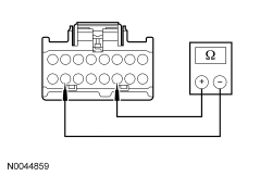 | Yes
GO to AZ16 . No GO to AZ15 . | ||||||||||||
| AZ15 CHECK THE BLOWER MOTOR SPEED CONTROL RESISTANCE | |||||||||||||
 | Yes
REPAIR the circuit(s). CLEAR the DTCs. REPEAT the self-test. DISCONNECT the battery ground cable. CONNECT passenger seat side air bag C337 and passenger safety belt buckle C3066. CONNECT driver seat side air bag C367 and driver safety belt buckle C3065. REPOWER the SRS . REFER to Section 501-20B . No INSTALL a new cushion TED . REFER to Seat Cushion Thermo-Electric Device in this section. CLEAR the DTCs. REPEAT the self-test. DISCONNECT the battery ground cable. CONNECT passenger seat side air bag C337 and passenger safety belt buckle C3066. CONNECT driver seat side air bag C367 and driver safety belt buckle C3065. REPOWER the SRS . REFER to Section 501-20B . | ||||||||||||
| AZ16 CHECK THE THERMISTOR FEED CIRCUIT FOR A SHORT TO VOLTAGE | |||||||||||||
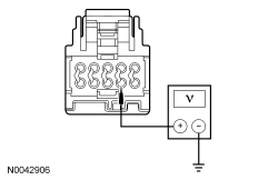 | Yes
REPAIR the circuit. CLEAR the DTCs. REPEAT the self-test. DISCONNECT the battery ground cable. CONNECT passenger seat side air bag C337 and passenger safety belt buckle C3066. CONNECT driver seat side air bag C367 and driver safety belt buckle C3065. REPOWER the SRS . REFER to Section 501-20B . No GO to AZ17 . | ||||||||||||
| AZ17 CHECK THE THERMISTOR FEED CIRCUIT FOR A SHORT TO GROUND | |||||||||||||
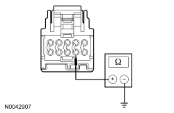 | Yes
GO to AZ18 . No REPAIR the circuit. CLEAR the DTCs. REPEAT the self-test. DISCONNECT the battery ground cable. CONNECT passenger seat side air bag C337 and passenger safety belt buckle C3066. CONNECT driver seat side air bag C367 and driver safety belt buckle C3065. REPOWER the SRS . REFER to Section 501-20B . | ||||||||||||
| AZ18 CHECK THE TED THERMISTOR AND WIRING RESISTANCE AT THE DCSM | |||||||||||||
 | Yes
INSTALL a new DCSM . REFER to Dual Climate Controlled Seat Module (DCSM) in this section. CLEAR the DTCs. REPEAT the self-test. DISCONNECT the battery ground cable. CONNECT passenger seat side air bag C337 and passenger safety belt buckle C3066. CONNECT driver seat side air bag C367 and driver safety belt buckle C3065. REPOWER the SRS . REFER to Section 501-20B . No GO to AZ19 . | ||||||||||||
| AZ19 CHECK THE TED THERMISTOR RESISTANCE | |||||||||||||
 | Yes
REPAIR the circuit(s). CLEAR the DTCs. REPEAT the self-test. DISCONNECT the battery ground cable. CONNECT passenger seat side air bag C337 and passenger safety belt buckle C3066. CONNECT driver seat side air bag C367 and driver safety belt buckle C3065. REPOWER the SRS . REFER to Section 501-20B . No INSTALL a new cushion TED . REFER to Seat Cushion Thermo-Electric Device in this section. CLEAR the DTCs. REPEAT the self-test. DISCONNECT the battery ground cable. CONNECT passenger seat side air bag C337 and passenger safety belt buckle C3066. CONNECT driver seat side air bag C367 and driver safety belt buckle C3065. REPOWER the SRS . REFER to Section 501-20B . | ||||||||||||
| AZ20 CHECK FOR CORRECT TED INSTALLATION AND FOR CRUSHED FOAM | |||||||||||||
| Yes
GO to AZ21 . No CORRECTLY install the backrest TED or INSTALL a new seat backrest foam pad and/or climate controlled seat manifold. CLEAR the DTCs. REPEAT the self-test. DISCONNECT the battery ground cable. REPOWER the SRS . REFER to Section 501-20B . | ||||||||||||
| AZ21 CHECK THE CUSHION TED GROUND CIRCUIT FOR A SHORT TO VOLTAGE | |||||||||||||
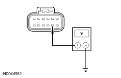 | Yes
REPAIR the circuit. CLEAR the DTCs. REPEAT the self-test. DISCONNECT the battery ground cable. CONNECT passenger seat side air bag C337 and passenger safety belt buckle C3066. CONNECT driver seat side air bag C367 and driver safety belt buckle C3065. REPOWER the SRS . REFER to Section 501-20B . No GO to AZ22 . | ||||||||||||
| AZ22 CHECK THE CUSHION TED FEED CIRCUIT FOR A SHORT TO GROUND | |||||||||||||
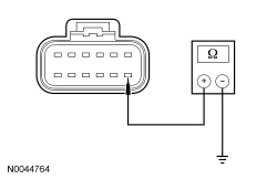 | Yes
GO to AZ23 . No REPAIR the circuit. CLEAR the DTCs. REPEAT the self-test. DISCONNECT the battery ground cable. CONNECT passenger seat side air bag C337 and passenger safety belt buckle C3066. CONNECT driver seat side air bag C367 and driver safety belt buckle C3065. REPOWER the SRS . REFER to Section 501-20B . | ||||||||||||
| AZ23 CHECK THE RESISTANCE OF THE CUSHION TED AND WIRING | |||||||||||||
 | Yes
GO to AZ25 . No GO to AZ24 . | ||||||||||||
| AZ24 CHECK THE CUSHION TED RESISTANCE | |||||||||||||
 | Yes
REPAIR the circuit(s). CLEAR the DTCs. REPEAT the self-test. DISCONNECT the battery ground cable. CONNECT passenger seat side air bag C337 and passenger safety belt buckle C3066. CONNECT driver seat side air bag C367 and driver safety belt buckle C3065. REPOWER the SRS . REFER to Section 501-20B . No INSTALL a new cushion TED . REFER to Seat Cushion Thermo-Electric Device in this section. CLEAR the DTCs. REPEAT the self-test. DISCONNECT the battery ground cable. CONNECT passenger seat side air bag C337 and passenger safety belt buckle C3066. CONNECT driver seat side air bag C367 and driver safety belt buckle C3065. REPOWER the SRS . REFER to Section 501-20B . | ||||||||||||
| AZ25 CHECK THE BLOWER MOTOR FEED AND SPEED CONTROL CIRCUITS FOR A SHORT TO VOLTAGE | |||||||||||||
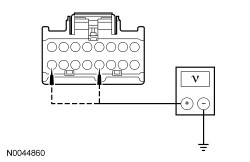 | Yes
REPAIR the circuit(s). CLEAR the DTCs. REPEAT the self-test. DISCONNECT the battery ground cable. CONNECT passenger seat side air bag C337 and passenger safety belt buckle C3066. CONNECT driver seat side air bag C367 and driver safety belt buckle C3065. REPOWER the SRS . REFER to Section 501-20B . No GO to AZ26 . | ||||||||||||
| AZ26 CHECK THE BLOWER MOTOR AND SPEED CONTROL FEED CIRCUITS FOR A SHORT TO GROUND | |||||||||||||
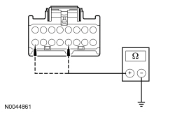 | Yes
GO to AZ27 . No REPAIR the circuit(s). CLEAR the DTCs. REPEAT the self-test. DISCONNECT the battery ground cable. CONNECT passenger seat side air bag C337 and passenger safety belt buckle C3066. CONNECT driver seat side air bag C367 and driver safety belt buckle C3065. REPOWER the SRS . REFER to Section 501-20B . | ||||||||||||
| AZ27 CHECK THE BLOWER MOTOR AND WIRING RESISTANCE | |||||||||||||
 | Yes
GO to AZ29 . No GO to AZ28 . | ||||||||||||
| AZ28 CHECK THE BLOWER MOTOR RESISTANCE | |||||||||||||
 | Yes
REPAIR the circuit(s). CLEAR the DTCs. REPEAT the self-test. DISCONNECT the battery ground cable. CONNECT passenger seat side air bag C337 and passenger safety belt buckle C3066. CONNECT driver seat side air bag C367 and driver safety belt buckle C3065. REPOWER the SRS . REFER to Section 501-20B . No INSTALL a new backrest TED . REFER to Seat Backrest Thermo-Electric Device in this section. CLEAR the DTCs. REPEAT the self-test. DISCONNECT the battery ground cable. CONNECT passenger seat side air bag C337 and passenger safety belt buckle C3066. CONNECT driver seat side air bag C367 and driver safety belt buckle C3065. REPOWER the SRS . REFER to Section 501-20B . | ||||||||||||
| AZ29 CHECK THE BLOWER MOTOR SPEED CONTROL AND CIRCUIT RESISTANCE | |||||||||||||
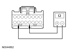 | Yes
GO to AZ31 . No GO to AZ30 . | ||||||||||||
| AZ30 CHECK THE BLOWER MOTOR SPEED CONTROL RESISTANCE | |||||||||||||
 | Yes
REPAIR the circuit(s). CLEAR the DTCs. REPEAT the self-test. DISCONNECT the battery ground cable. CONNECT passenger seat side air bag C337 and passenger safety belt buckle C3066. CONNECT driver seat side air bag C367 and driver safety belt buckle C3065. REPOWER the SRS . REFER to Section 501-20B . No INSTALL a new backrest TED . REFER to Seat Backrest Thermo-Electric Device in this section. CLEAR the DTCs. REPEAT the self-test. DISCONNECT the battery ground cable. CONNECT passenger seat side air bag C337 and passenger safety belt buckle C3066. CONNECT driver seat side air bag C367 and driver safety belt buckle C3065. REPOWER the SRS . REFER to Section 501-20B . | ||||||||||||
| AZ31 CHECK THE THERMISTOR FEED CIRCUIT FOR A SHORT TO VOLTAGE | |||||||||||||
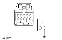 | Yes
REPAIR the circuit. CLEAR the DTCs. REPEAT the self-test. DISCONNECT the battery ground cable. CONNECT passenger seat side air bag C337 and passenger safety belt buckle C3066. CONNECT driver seat side air bag C367 and driver safety belt buckle C3065. REPOWER the SRS . REFER to Section 501-20B . No GO to AZ32 . | ||||||||||||
| AZ32 CHECK THE THERMISTOR FEED CIRCUIT FOR A SHORT TO GROUND | |||||||||||||
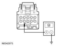 | Yes
GO to AZ33 . No REPAIR the circuit. CLEAR the DTCs. REPEAT the self-test. DISCONNECT the battery ground cable. CONNECT passenger seat side air bag C337 and passenger safety belt buckle C3066. CONNECT driver seat side air bag C367 and driver safety belt buckle C3065. REPOWER the SRS . REFER to Section 501-20B . | ||||||||||||
| AZ33 CHECK THE TED THERMISTOR AND WIRING RESISTANCE | |||||||||||||
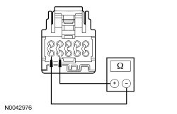 | Yes
INSTALL a new DCSM . REFER to Dual Climate Controlled Seat Module (DCSM) in this section. CLEAR the DTCs. REPEAT the self-test. DISCONNECT the battery ground cable. CONNECT passenger seat side air bag C337 and passenger safety belt buckle C3066. CONNECT driver seat side air bag C367 and driver safety belt buckle C3065. REPOWER the SRS . REFER to Section 501-20B . No GO to AZ34 . | ||||||||||||
| AZ34 CHECK THE TED THERMISTOR RESISTANCE | |||||||||||||
 | Yes
REPAIR the circuit(s). CLEAR the DTCs. REPEAT the self-test. DISCONNECT the battery ground cable. CONNECT passenger seat side air bag C337 and passenger safety belt buckle C3066. CONNECT driver seat side air bag C367 and driver safety belt buckle C3065. REPOWER the SRS . REFER to Section 501-20B . No INSTALL a new backrest TED . REFER to Seat Backrest Thermo-Electric Device in this section. CLEAR the DTCs. REPEAT the self-test. DISCONNECT the battery ground cable. CONNECT passenger seat side air bag C337 and passenger safety belt buckle C3066. CONNECT driver seat side air bag C367 and driver safety belt buckle C3065. REPOWER the SRS . REFER to Section 501-20B . |
Pinpoint Test BA: DTC B272D
Refer to Wiring Diagrams Cell 119 , Climate Controlled Seats for schematic and connector information.
The Dual Climate Controlled Seat Module (DCSM) is supplied voltage at all times, but the climate controlled seat system only operates with the engine running. The system can be operated with the ignition ON engine OFF by using a scan tool to bypass the climate controlled seat buttons on the touchscreen interface. When commanding a heat or cool mode operation in this manner, the climate controlled seat system only operates in 15 second intervals. Both voltage supply circuits are spliced together internal to the DCSM , so if one circuit becomes open, both seats can still be operated. However, if a fault occurs setting a DTC specific to either climate controlled seat, only the affected seat is disabled by the DCSM .
The seat cushion is equipped with a Thermo-Electric Device (TED) assembly that includes a seat blower (fan motor, serviced as an assembly with the TED ). Similarly, the seat backrest is also equipped with its own TED assembly with blower. Cabin air is drawn through the blower and distributed to each of the TED modules located in the seat cushion and backrest. The TEDs then heat or cool the air. The air is then directed into the foam pad and manifold where it is distributed along the surface of the cushion and backrest of the seat. Once the system is activated, the DCSM uses a set of flexible algorithms to control the heating/cooling modes and the blower speed dependant on the commanded climate controlled seat settings.
A differential fault occurs when the cushion and backrest TEDs on an affected seat are reporting very different temperatures to the DCSM . This may result from an air flow restriction or a circuit fault of either TED area. If a TED and manifold is clear of obstruction and is operational, check the other TED and circuitry on the seat. It is important to note that a TED with a higher temperature may be operating correctly and is not the area of concern. The other TED may be indicating a much lower temperature, causing the DTC to set.
NOTICE: When taking measurements at Dual Climate Controlled Seat Module (DCSM) harness connectors, do not insert the electrical probes into the female connector pins. Inserting the probes into connector pins can cause intermittent or open electrical connections after reassembly resulting in Diagnostic Trouble Codes (DTCs) and system failure. Touching the tip of these connector pins is recommended instead.
NOTE: The air bag warning indicator illuminates when the correct Restraints Control Module (RCM) fuse is removed and the ignition switch is on.
NOTE: The Supplemental Restraint System (SRS) must be fully operational and free of faults before releasing the vehicle to the customer.
| Test Step | Result / Action to Take | ||||||||||||
|---|---|---|---|---|---|---|---|---|---|---|---|---|---|
| BA1 CHECK THE DCSM FOR DTCs | |||||||||||||
| Yes
For DTC B272A, GO to Pinpoint Test AX . For DTC B272B, GO to Pinpoint Test AY . No GO to BA2 . | ||||||||||||
| BA2 MONITOR THE TED TEMPERATURE PIDs | |||||||||||||
| Yes
GO to BA3 . No If the front passenger seat cushion PID varies 10°C (18°F) or more from ambient temperature, GO to BA16 . If the front passenger seat backrest PID varies 10°C (18°F) or more from ambient temperature, GO to BA32 . | ||||||||||||
| BA3 CONFIRM THE FAULT IS IN THE SEAT CUSHION OR BACKREST TED | |||||||||||||
| Yes
If the front passenger seat cushion PID is 60°C (108°F) hotter than the backrest PID, GO to BA5 . If the front passenger seat backrest PID is 60°C (108°F) hotter than the cushion PID, GO to BA20 . No GO to BA4 . | ||||||||||||
| BA4 CHECK THE TEDs COOLING PERFORMANCE | |||||||||||||
| Yes
The DTC may have been set by extreme cabin temperatures or excessive sunload on the seat causing the system to enter recovery mode. Occupant size and weight characteristics can also be a factor. CLEAR the DTCs. REPEAT the self-test. TEST the system for normal operation. If a concern cannot be found or duplicated, RETURN the vehicle to the customer. No CHECK the affected seat cushion or backrest for correct installation of the climate controlled seat components ( TED , manifold, plenum, air ducts and foam pad). CHECK for airflow restrictions ( TED inlets and outlets, TED -to-manifold or plenum connections, filters and ducts) and REPAIR as needed. CHECK for an intermittent wiring fault. REPAIR as needed. CLEAR the DTCs. REPEAT the self-test. | ||||||||||||
| BA5 CHECK FOR CORRECT TED INSTALLATION AND FOR CRUSHED FOAM | |||||||||||||
| Yes
GO to BA6 . No Correctly INSTALL the cushion TED or INSTALL a new seat cushion foam pad and/or climate controlled seat manifold. CLEAR the DTCs. REPEAT the self-test. DISCONNECT the battery ground cable. REPOWER the SRS . REFER to Section 501-20B . | ||||||||||||
| BA6 CHECK THE BACKREST TED GROUND CIRCUIT FOR A SHORT TO VOLTAGE | |||||||||||||
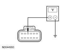 | Yes
REPAIR the circuit. CLEAR the DTCs. REPEAT the self-test. DISCONNECT the battery ground cable. CONNECT passenger seat side air bag C337 and passenger safety belt buckle C3066. REPOWER the SRS . REFER to Section 501-20B . No GO to BA7 . | ||||||||||||
| BA7 CHECK THE BACKREST TED FEED CIRCUIT FOR A SHORT TO GROUND | |||||||||||||
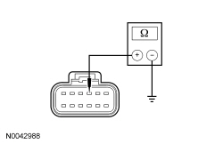 | Yes
GO to BA8 . No REPAIR the circuit. CLEAR the DTCs. REPEAT the self-test. DISCONNECT the battery ground cable. CONNECT passenger seat side air bag C337 and passenger safety belt buckle C3066. REPOWER the SRS . REFER to Section 501-20B . | ||||||||||||
| BA8 CHECK THE RESISTANCE OF THE BACKREST TED AND WIRING | |||||||||||||
 | Yes
GO to BA10 . No GO to BA9 . | ||||||||||||
| BA9 CHECK THE RESISTANCE OF THE BACKREST TED | |||||||||||||
 | Yes
REPAIR the circuit. CLEAR the DTCs. REPEAT the self-test. DISCONNECT the battery ground cable. CONNECT passenger seat side air bag C337 and passenger safety belt buckle C3066. REPOWER the SRS . REFER to Section 501-20B . No INSTALL a new backrest TED . REFER to Seat Backrest Thermo-Electric Device in this section. CLEAR the DTCs. REPEAT the self-test. DISCONNECT the battery ground cable. CONNECT passenger seat side air bag C337 and passenger safety belt buckle C3066. REPOWER the SRS . REFER to Section 501-20B . | ||||||||||||
| BA10 CHECK THE BLOWER MOTOR FEED AND SPEED CONTROL CIRCUITS FOR A SHORT TO VOLTAGE | |||||||||||||
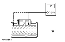 | Yes
REPAIR the circuit(s). CLEAR the DTCs. REPEAT the self-test. DISCONNECT the battery ground cable. CONNECT passenger seat side air bag C337 and passenger safety belt buckle C3066. REPOWER the SRS . REFER to Section 501-20B . No GO to BA11 . | ||||||||||||
| BA11 CHECK THE BLOWER MOTOR FEED AND SPEED CONTROL CIRCUITS FOR A SHORT TO GROUND | |||||||||||||
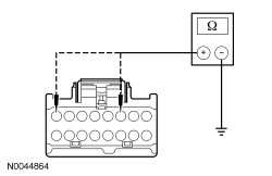 | Yes
GO to BA12 . No REPAIR the circuit(s). CLEAR the DTCs. REPEAT the self-test. DISCONNECT the battery ground cable. CONNECT passenger seat side air bag C337 and passenger safety belt buckle C3066. REPOWER the SRS . REFER to Section 501-20B . | ||||||||||||
| BA12 CHECK THE BLOWER MOTOR AND WIRING RESISTANCE | |||||||||||||
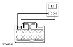 | Yes
GO to BA14 . No GO to BA13 . | ||||||||||||
| BA13 CHECK THE BLOWER MOTOR RESISTANCE | |||||||||||||
 | Yes
REPAIR the circuit(s). CLEAR the DTCs. REPEAT the self-test. DISCONNECT the battery ground cable. CONNECT passenger seat side air bag C337 and passenger safety belt buckle C3066. REPOWER the SRS . REFER to Section 501-20B . No INSTALL a new cushion TED . REFER to Seat Cushion Thermo-Electric Device in this section. CLEAR the DTCs. REPEAT the self-test. DISCONNECT the battery ground cable. CONNECT passenger seat side air bag C337 and passenger safety belt buckle C3066. REPOWER the SRS . REFER to Section 501-20B . | ||||||||||||
| BA14 CHECK THE BLOWER MOTOR SPEED CONTROL AND CIRCUIT RESISTANCE | |||||||||||||
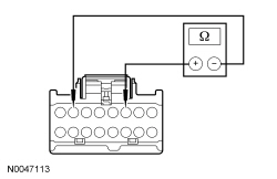 | Yes
GO to BA16 . No GO to BA15 . | ||||||||||||
| BA15 CHECK THE BLOWER MOTOR SPEED CONTROL RESISTANCE | |||||||||||||
 | Yes
REPAIR the circuit(s). CLEAR the DTCs. REPEAT the self-test. DISCONNECT the battery ground cable. CONNECT passenger seat side air bag C337 and passenger safety belt buckle C3066. REPOWER the SRS . REFER to Section 501-20B . No INSTALL a new cushion TED . REFER to Seat Cushion Thermo-Electric Device in this section. CLEAR the DTCs. REPEAT the self-test. DISCONNECT the battery ground cable. CONNECT passenger seat side air bag C337 and passenger safety belt buckle C3066. REPOWER the SRS . REFER to Section 501-20B . | ||||||||||||
| BA16 CHECK THE THERMISTOR FEED CIRCUIT FOR A SHORT TO VOLTAGE | |||||||||||||
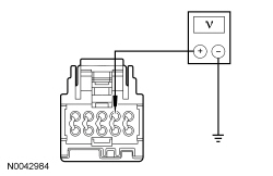 | Yes
REPAIR the circuit. CLEAR the DTCs. REPEAT the self-test. DISCONNECT the battery ground cable. CONNECT passenger seat side air bag C337 and passenger safety belt buckle C3066. REPOWER the SRS . REFER to Section 501-20B . No GO to BA17 . | ||||||||||||
| BA17 CHECK THE THERMISTOR FEED CIRCUIT FOR A SHORT TO GROUND | |||||||||||||
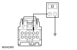 | Yes
GO to BA18 . No REPAIR the circuit. CLEAR the DTCs. REPEAT the self-test. DISCONNECT the battery ground cable. CONNECT passenger seat side air bag C337 and passenger safety belt buckle C3066. REPOWER the SRS . REFER to Section 501-20B . | ||||||||||||
| BA18 CHECK THE THERMISTOR AND WIRING RESISTANCE | |||||||||||||
 | Yes
INSTALL a new DCSM . REFER to Dual Climate Controlled Seat Module (DCSM) in this section. CLEAR the DTCs. REPEAT the self-test. DISCONNECT the battery ground cable. CONNECT passenger seat side air bag C337 and passenger safety belt buckle C3066. REPOWER the SRS . REFER to Section 501-20B . No GO to BA19 . | ||||||||||||
| BA19 CHECK THE THERMISTOR RESISTANCE | |||||||||||||
 | Yes
REPAIR the circuit(s). CLEAR the DTCs. REPEAT the self-test. DISCONNECT the battery ground cable. CONNECT passenger seat side air bag C337 and passenger safety belt buckle C3066. REPOWER the SRS . REFER to Section 501-20B . No INSTALL a new cushion TED . REFER to Seat Cushion Thermo-Electric Device in this section. CLEAR the DTCs. REPEAT the self-test. DISCONNECT the battery ground cable. CONNECT passenger seat side air bag C337 and passenger safety belt buckle C3066. REPOWER the SRS . REFER to Section 501-20B . | ||||||||||||
| BA20 CHECK FOR CORRECT TED INSTALLATION AND FOR CRUSHED FOAM | |||||||||||||
| Yes
GO to BA21 . No Correctly INSTALL the backrest TED or INSTALL a new seat backrest foam pad and/or climate controlled seat manifold. CLEAR the DTCs. REPEAT the self-test. DISCONNECT the battery ground cable. REPOWER the SRS . REFER to Section 501-20B . | ||||||||||||
| BA21 CHECK THE CUSHION TED GROUND CIRCUIT FOR A SHORT TO VOLTAGE | |||||||||||||
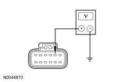 | Yes
REPAIR the circuit. CLEAR the DTCs. REPEAT the self-test. DISCONNECT the battery ground cable. CONNECT passenger seat side air bag C337 and passenger safety belt buckle C3066. REPOWER the SRS . REFER to Section 501-20B . No GO to BA22 . | ||||||||||||
| BA22 CHECK THE CUSHION TED FEED CIRCUIT FOR A SHORT TO GROUND | |||||||||||||
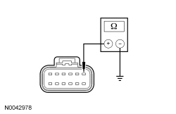 | Yes
GO to BA23 . No REPAIR the circuit. CLEAR the DTCs. REPEAT the self-test. DISCONNECT the battery ground cable. CONNECT passenger seat side air bag C337 and passenger safety belt buckle C3066. REPOWER the SRS . REFER to Section 501-20B . | ||||||||||||
| BA23 CHECK THE CUSHION TED AND WIRING RESISTANCE | |||||||||||||
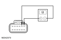 | Yes
GO to BA25 . No GO to BA24 . | ||||||||||||
| BA24 CHECK THE CUSHION TED RESISTANCE | |||||||||||||
 | Yes
REPAIR the circuit. CLEAR the DTCs. REPEAT the self-test. DISCONNECT the battery ground cable. CONNECT passenger seat side air bag C337 and passenger safety belt buckle C3066. REPOWER the SRS . REFER to Section 501-20B . No INSTALL a new cushion TED . REFER to Seat Cushion Thermo-Electric Device in this section. CLEAR the DTCs. REPEAT the self-test. DISCONNECT the battery ground cable. CONNECT passenger seat side air bag C337 and passenger safety belt buckle C3066. REPOWER the SRS . REFER to Section 501-20B . | ||||||||||||
| BA25 CHECK THE BLOWER MOTOR FEED AND SPEED CONTROL CIRCUITS FOR A SHORT TO VOLTAGE | |||||||||||||
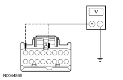 | Yes
REPAIR the circuit(s). CLEAR the DTCs. REPEAT the self-test. DISCONNECT the battery ground cable. CONNECT passenger seat side air bag C337 and passenger safety belt buckle C3066. REPOWER the SRS . REFER to Section 501-20B . No GO to BA26 . | ||||||||||||
| BA26 CHECK THE BLOWER MOTOR FEED AND SPEED CONTROL CIRCUITS FOR A SHORT TO GROUND | |||||||||||||
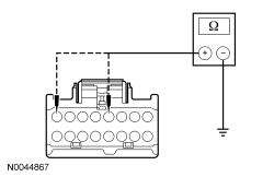 | Yes
GO to BA27 . No REPAIR the circuit(s). CLEAR the DTCs. REPEAT the self-test. DISCONNECT the battery ground cable. CONNECT passenger seat side air bag C337 and passenger safety belt buckle C3066. REPOWER the SRS . REFER to Section 501-20B . | ||||||||||||
| BA27 CHECK THE BLOWER MOTOR AND WIRING RESISTANCE | |||||||||||||
 | Yes
GO to BA29 . No GO to BA28 . | ||||||||||||
| BA28 CHECK THE BLOWER MOTOR RESISTANCE | |||||||||||||
 | Yes
REPAIR the circuit(s). CLEAR the DTCs. REPEAT the self-test. DISCONNECT the battery ground cable. CONNECT passenger seat side air bag C337 and passenger safety belt buckle C3066. REPOWER the SRS . REFER to Section 501-20B . No INSTALL a new backrest TED . REFER to Seat Backrest Thermo-Electric Device in this section. CLEAR the DTCs. REPEAT the self-test. DISCONNECT the battery ground cable. CONNECT passenger seat side air bag C337 and passenger safety belt buckle C3066. REPOWER the SRS . REFER to Section 501-20B . | ||||||||||||
| BA29 CHECK THE BLOWER MOTOR GROUND CIRCUIT TO BLOWER MOTOR SPEED CONTROL CIRCUIT RESISTANCE | |||||||||||||
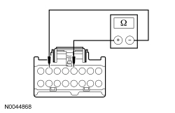 | Yes
GO to BA31 . No GO to BA30 . | ||||||||||||
| BA30 CHECK THE BLOWER MOTOR SPEED CONTROL RESISTANCE | |||||||||||||
 | Yes
REPAIR the circuit(s). CLEAR the DTCs. REPEAT the self-test. DISCONNECT the battery ground cable. CONNECT passenger seat side air bag C337 and passenger safety belt buckle C3066. REPOWER the SRS . REFER to Section 501-20B . No INSTALL a new backrest TED . REFER to Seat Backrest Thermo-Electric Device in this section. CLEAR the DTCs. REPEAT the self-test. DISCONNECT the battery ground cable. CONNECT passenger seat side air bag C337 and passenger safety belt buckle C3066. REPOWER the SRS . REFER to Section 501-20B . | ||||||||||||
| BA31 CHECK THE THERMISTOR FEED CIRCUIT FOR A SHORT TO VOLTAGE | |||||||||||||
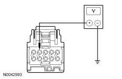 | Yes
REPAIR the circuit. CLEAR the DTCs. REPEAT the self-test. DISCONNECT the battery ground cable. CONNECT passenger seat side air bag C337 and passenger safety belt buckle C3066. REPOWER the SRS . REFER to Section 501-20B . No GO to BA32 . | ||||||||||||
| BA32 CHECK THE THERMISTOR FEED CIRCUIT FOR A SHORT TO GROUND | |||||||||||||
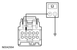 | Yes
GO to BA33 . No REPAIR the circuit. CLEAR the DTCs. REPEAT the self-test. DISCONNECT the battery ground cable. CONNECT passenger seat side air bag C337 and passenger safety belt buckle C3066. REPOWER the SRS . REFER to Section 501-20B . | ||||||||||||
| BA33 CHECK THE THERMISTOR AND WIRING RESISTANCE AT THE DCSM | |||||||||||||
 | Yes
INSTALL a new DCSM . REFER to Dual Climate Controlled Seat Module (DCSM) in this section. CLEAR the DTCs. REPEAT the self-test. DISCONNECT the battery ground cable. CONNECT passenger seat side air bag C337 and passenger safety belt buckle C3066. REPOWER the SRS . REFER to Section 501-20B . No GO to BA34 . | ||||||||||||
| BA34 CHECK THE TED THERMISTOR RESISTANCE | |||||||||||||
 | Yes
REPAIR the circuit(s). CLEAR the DTCs. REPEAT the self-test. DISCONNECT the battery ground cable. CONNECT passenger seat side air bag C337 and passenger safety belt buckle C3066. REPOWER the SRS . REFER to Section 501-20B . No INSTALL a new backrest TED . REFER to Seat Backrest Thermo-Electric Device in this section. CLEAR the DTCs. REPEAT the self-test. DISCONNECT the battery ground cable. CONNECT passenger seat side air bag C337 and passenger safety belt buckle C3066. REPOWER the SRS . REFER to Section 501-20B . |
Pinpoint Test BB: DTC B272E
NOTE: This DTC sets for an open or short to voltage. See DTC setting description below.
Refer to Wiring Diagrams Cell 119 , Climate Controlled Seats for schematic and connector information.
The driver climate controlled seat blowers are located within the backrest and cushion Thermo-Electric Devices (TEDs). The Dual Climate Controlled Seat Module (DCSM) supplies voltage and ground to both blowers. The blowers are independently controlled by separate speed control circuits from the DCSM .
NOTICE: When taking measurements at Dual Climate Controlled Seat Module (DCSM) harness connectors, do not insert the electrical probes into the female connector pins. Inserting the probes into connector pins can cause intermittent or open electrical connections after reassembly resulting in Diagnostic Trouble Codes (DTCs) and system failure. Touching the tip of these connector pins is recommended instead.
NOTE: The air bag warning indicator illuminates when the correct Restraints Control Module (RCM) fuse is removed and the ignition switch is on.
NOTE: The Supplemental Restraint System (SRS) must be fully operational and free of faults before releasing the vehicle to the customer.
| Test Step | Result / Action to Take | |||||||||
|---|---|---|---|---|---|---|---|---|---|---|
| BB1 CHECK THE TED BLOWER MOTOR CIRCUITS FOR A SHORT TO VOLTAGE | ||||||||||
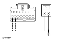 | Yes
REPAIR the circuit(s). CLEAR the DTCs. REPEAT the self-test. DISCONNECT the battery ground cable. CONNECT passenger seat side air bag C337 and passenger safety belt buckle C3066. CONNECT driver seat side air bag C367 and driver safety belt buckle C3065. REPOWER the SRS . REFER to Section 501-20B . No GO to BB2 . | |||||||||
| BB2 CHECK THE TED BLOWER MOTOR CIRCUITS FOR AN OPEN | ||||||||||
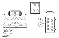 | Yes
GO to BB3 . No REPAIR the circuit(s). CLEAR the DTCs. REPEAT the self-test. DISCONNECT the battery ground cable. CONNECT passenger seat side air bag C337 and passenger safety belt buckle C3066. CONNECT driver seat side air bag C367 and driver safety belt buckle C3065. REPOWER the SRS . REFER to Section 501-20B . | |||||||||
| BB3 CHECK THE RESISTANCE OF THE CUSHION AND BACKREST TED BLOWER MOTORS | ||||||||||
 | Yes
INSTALL a new DCSM . REFER to Dual Climate Controlled Seat Module (DCSM) in this section. CLEAR the DTCs. REPEAT the self-test. DISCONNECT the battery ground cable. CONNECT passenger seat side air bag C337 and passenger safety belt buckle C3066. CONNECT driver seat side air bag C367 and driver safety belt buckle C3065. REPOWER the SRS . REFER to Section 501-20B . No If the cushion TED resistance is not between 4,000 and 10,000 ohms, INSTALL a new cushion TED . REFER to Seat Cushion Thermo-Electric Device in this section. CLEAR the DTCs. REPEAT the self-test. If backrest the TED resistance is not between 4,000 and 10,000 ohms, INSTALL a new backrest TED . REFER to Seat Backrest Thermo-Electric Device in this section. CLEAR the DTCs. REPEAT the self-test. DISCONNECT the battery ground cable. CONNECT passenger seat side air bag C337 and passenger safety belt buckle C3066. CONNECT driver seat side air bag C367 and driver safety belt buckle C3065. REPOWER the SRS . REFER to Section 501-20B . |
Pinpoint Test BC: DTC B272F
NOTE: This DTC sets for an open or short to voltage. See DTC setting description below.
Refer to Wiring Diagrams Cell 119 , Climate Controlled Seats for schematic and connector information.
The passenger climate controlled seat blowers are located within the backrest and cushion Thermo-Electric Devices (TEDs). The Dual Climate Controlled Seat Module (DCSM) supplies voltage and ground to both blowers. The blowers are independently controlled by separate speed control circuits from the DCSM .
NOTICE: When taking measurements at Dual Climate Controlled Seat Module (DCSM) harness connectors, do not insert the electrical probes into the female connector pins. Inserting the probes into connector pins can cause intermittent or open electrical connections after reassembly resulting in Diagnostic Trouble Codes (DTCs) and system failure. Touching the tip of these connector pins is recommended instead.
NOTE: The air bag warning indicator illuminates when the correct Restraints Control Module (RCM) fuse is removed and the ignition switch is on.
NOTE: The Supplemental Restraint System (SRS) must be fully operational and free of faults before releasing the vehicle to the customer.
| Test Step | Result / Action to Take | |||||||||
|---|---|---|---|---|---|---|---|---|---|---|
| BC1 CHECK THE TED BLOWER MOTOR CIRCUITS FOR A SHORT TO VOLTAGE | ||||||||||
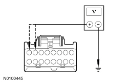 | Yes
REPAIR the circuit(s). CLEAR the DTCs. REPEAT the self-test. DISCONNECT the battery ground cable. CONNECT passenger seat side air bag C337 and passenger safety belt buckle C3066. REPOWER the SRS . REFER to Section 501-20B . No GO to BC2 . | |||||||||
| BC2 CHECK THE TED BLOWER MOTOR CIRCUITS FOR AN OPEN | ||||||||||
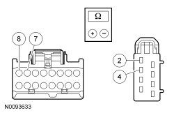 | Yes
GO to BC3 . No REPAIR the circuit(s). CLEAR the DTCs. REPEAT the self-test. DISCONNECT the battery ground cable. CONNECT passenger seat side air bag C337 and passenger safety belt buckle C3066. REPOWER the SRS . REFER to Section 501-20B . | |||||||||
| BC3 CHECK THE RESISTANCE OF THE CUSHION AND BACKREST TED BLOWER MOTORS | ||||||||||
 | Yes
INSTALL a new DCSM . REFER to Dual Climate Controlled Seat Module (DCSM) in this section. CLEAR the DTCs. REPEAT the self-test. DISCONNECT the battery ground cable. CONNECT passenger seat side air bag C337 and passenger safety belt buckle C3066. REPOWER the SRS . REFER to Section 501-20B . No If the cushion TED resistance is not between 4,000 and 10,000 ohms, INSTALL a new cushion TED . REFER to Seat Cushion Thermo-Electric Device in this section. CLEAR the DTCs. REPEAT the self-test. If backrest the TED resistance is not between 4,000 and 10,000 ohms, INSTALL a new backrest TED . REFER to Seat Backrest Thermo-Electric Device in this section. CLEAR the DTCs. REPEAT the self-test. DISCONNECT the battery ground cable. CONNECT passenger seat side air bag C337 and passenger safety belt buckle C3066. REPOWER the SRS . REFER to Section 501-20B . |
Pinpoint Test BD: DTC B2730
Refer to Wiring Diagrams Cell 119 , Climate Controlled Seats for schematic and connector information.
The Dual Climate Controlled Seat Module (DCSM) monitors seat backrest temperature while it supplies voltage and ground to both blower motors. The DCSM also supplies a variable voltage signal to control the blower speed. Cabin air enters the blower through a filter attached to the Thermo-Electric Device (TED) housing. Heated or cooled air exits the TED and flows through a manifold attached to the foam pad.
NOTICE: When taking measurements at Dual Climate Controlled Seat Module (DCSM) harness connectors, do not insert the electrical probes into the female connector pins. Inserting the probes into connector pins can cause intermittent or open electrical connections after reassembly resulting in Diagnostic Trouble Codes (DTCs) and system failure. Touching the tip of these connector pins is recommended instead.
NOTE: The air bag warning indicator illuminates when the correct Restraints Control Module (RCM) fuse is removed and the ignition is ON.
NOTE: The Supplemental Restraint System (SRS) must be fully operational and free of faults before releasing the vehicle to the customer.
| Test Step | Result / Action to Take | ||||||||||||
|---|---|---|---|---|---|---|---|---|---|---|---|---|---|
| BD1 CHECK THE DCSM FOR ON-DEMAND DTCs | |||||||||||||
| Yes
GO to BD2 . No GO to BD5 . | ||||||||||||
| BD2 CHECK THE DRIVER SEAT BACKREST TED THERMISTOR CIRCUITS FOR A SHORT TO GROUND | |||||||||||||
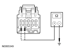 | Yes
GO to BD3 . No REPAIR the circuit(s). CLEAR the DTCs. REPEAT the self-test. DISCONNECT the battery ground cable. CONNECT driver seat side air bag C367 and passenger seat side air bag C337. REPOWER the SRS . REFER to Section 501-20B . | ||||||||||||
| BD3 CHECK THE DRIVER SEAT BACKREST TED THERMISTOR AND WIRING | |||||||||||||
 | Yes
GO to BD18 . No GO to BD4 . | ||||||||||||
| BD4 CHECK THE DRIVER SEAT BACKREST TED THERMISTOR | |||||||||||||
 | Yes
REPAIR circuit VHS35 (VT/OG) or RHS15 (GY/BN) for an open or high resistance. CLEAR the DTCs. REPEAT the self-test. DISCONNECT the battery ground cable. CONNECT driver seat side air bag C367 and passenger seat side air bag C337. REPOWER the SRS . REFER to Section 501-20B . No INSTALL a new driver seat backrest TED . REFER to Seat Backrest Thermo-Electric Device in this section. CLEAR the DTCs. REPEAT the self-test. DISCONNECT the battery ground cable. CONNECT driver seat side air bag C367 and passenger seat side air bag C337. REPOWER the SRS . REFER to Section 501-20B . | ||||||||||||
| BD5 CONFIRM THE FAULT WHILE MONITORING THE DCSM SEAT BACK THERMAL ELECTRIC DEVICE TEMPERATURE (BK_TEMP) AND SEAT CUSHION THERMAL ELECTRIC DEVICE TEMPERATURE (CSHTEMP) PIDs | |||||||||||||
| Yes
Fault not present at this time. Fault may have been set due to a past failure, incorrect use of the climate controlled seat system by repeated switching between heat and cool modes or due to excessive driver compartment temperature. CLEAR the DTCs. REPEAT the self-test. No If the BK_TEMP PID increases incrementally and is greater than 15°C (27°F) of the CSHTEMP PID, GO to BD6 . If the BK_TEMP PID increases quickly (temperature "jumps" and does not increase incrementally) and is greater than 15°C (27°F) of the CSHTEMP PID, GO to BD16 . | ||||||||||||
| BD6 COMPARE OPERATION OF THE DRIVER AND PASSENGER SEATS | |||||||||||||
| Yes
GO to BD7 . No If the airflow exhausting from the driver seat backrest TED is not comparable to the airflow exhausting from the passenger seat backrest TED , GO to BD8 . If the driver seat backrest TED blower operation changed while carrying out the wiggle test, IDENTIFY and REPAIR the wiring fault. CLEAR the DTCs. REPEAT the self-test. | ||||||||||||
| BD7 COMPARE OPERATION OF THE DRIVER AND PASSENGER SEATS WHILE OCCUPIED | |||||||||||||
| Yes
GO to BD16 . No INSTALL a new driver seat backrest foam pad and/or climate controlled seat manifold. CLEAR the DTCs. REPEAT the self-test. | ||||||||||||
| BD8 CHECK THE DRIVER SEAT BACKREST BLOWER FOR AN OBSTRUCTION OR RESTRICTED FILTER | |||||||||||||
| Yes
REMOVE the obstruction or INSTALL a new filter. CLEAR the DTCs. REPEAT the self-test. No GO to BD9 . | ||||||||||||
| BD9 CHECK THE DRIVER SEAT BACKREST BLOWER SPEED CONTROL CIRCUIT FOR AN OPEN | |||||||||||||
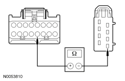 | Yes
GO to BD10 . No REPAIR the circuit. CLEAR the DTCs. REPEAT the self-test. DISCONNECT the battery ground cable. CONNECT driver seat side air bag C367 and passenger seat side air bag C337. REPOWER the SRS . REFER to Section 501-20B . | ||||||||||||
| BD10 CHECK THE DRIVER SEAT BACKREST BLOWER CIRCUIT FOR A SHORT TO VOLTAGE | |||||||||||||
 | Yes
REPAIR the circuit. CLEAR the DTCs. REPEAT the self-test. DISCONNECT the battery ground cable. CONNECT driver seat side air bag C367 and passenger seat side air bag C337. REPOWER the SRS . REFER to Section 501-20B . No GO to BD11 . | ||||||||||||
| BD11 CHECK THE DRIVER SEAT BACKREST BLOWER CIRCUIT FOR A SHORT TO GROUND | |||||||||||||
 | Yes
GO to BD12 . No REPAIR the circuit. CLEAR the DTCs. REPEAT the self-test. DISCONNECT the battery ground cable. CONNECT driver seat side air bag C367 and passenger seat side air bag C337. REPOWER the SRS . REFER to Section 501-20B . | ||||||||||||
| BD12 CHECK THE DRIVER SEAT BACKREST BLOWER CIRCUITS FOR AN OPEN | |||||||||||||
 | Yes
GO to BD13 . No REPAIR the circuit(s). CLEAR the DTCs. REPEAT the self-test. DISCONNECT the battery ground cable. CONNECT driver seat side air bag C367 and passenger seat side air bag C337. REPOWER the SRS . REFER to Section 501-20B . | ||||||||||||
| BD13 CHECK THE DRIVER SEAT BACKREST BLOWER RESISTANCE | |||||||||||||
 | Yes
GO to BD14 . No INSTALL a new driver seat backrest TED . REFER to Seat Backrest Thermo-Electric Device in this section. CLEAR the DTCs. REPEAT the self-test. DISCONNECT the battery ground cable. CONNECT driver seat side air bag C367 and passenger seat side air bag C337. REPOWER the SRS . REFER to Section 501-20B . | ||||||||||||
| BD14 CHECK THE DRIVER SEAT BACKREST BLOWER SPEED CONTROL RESISTANCE | |||||||||||||
 | Yes
GO to BD15 . No INSTALL a new driver seat backrest TED . REFER to Seat Backrest Thermo-Electric Device in this section. CLEAR the DTCs. REPEAT the self-test. DISCONNECT the battery ground cable. CONNECT driver seat side air bag C367 and passenger seat side air bag C337. REPOWER the SRS . REFER to Section 501-20B . | ||||||||||||
| BD15 CHECK THE DRIVER SEAT BACKREST TED INSTALLATION AND FOR CRUSHED SEAT BACKREST | |||||||||||||
| Yes
INSTALL the driver seat backrest cover and seat and GO to BD18 . No CORRECTLY install the driver seat backrest TED or INSTALL a new driver seat backrest foam pad and/or climate controlled seat manifold. CONNECT the battery ground cable. REFER to Section 414-01 . CLEAR the DTCs. REPEAT the self-test. DISCONNECT the battery ground cable. CONNECT driver seat side air bag C367 and passenger seat side air bag C337. REPOWER the SRS . REFER to Section 501-20B . | ||||||||||||
| BD16 CHECK THE DRIVER SEAT BACKREST TED THERMISTOR AND WIRING | |||||||||||||
 | Yes
GO to BD18 . No GO to BD17 . | ||||||||||||
| BD17 CHECK THE DRIVER SEAT BACKREST TED THERMISTOR | |||||||||||||
 | Yes
REPAIR circuit VHS35 (VT/OG) or RHS15 (GY/BN) for an open or high resistance. CLEAR the DTCs. REPEAT the self-test. DISCONNECT the battery ground cable. CONNECT driver seat side air bag C367 and passenger seat side air bag C337. REPOWER the SRS . REFER to Section 501-20B . No INSTALL a new TED . REFER to Seat Backrest Thermo-Electric Device in this section. CLEAR the DTCs. REPEAT the self-test. DISCONNECT the battery ground cable. CONNECT driver seat side air bag C367 and passenger seat side air bag C337. REPOWER the SRS . REFER to Section 501-20B . | ||||||||||||
| BD18 CHECK THE DRIVER SEAT BACKREST TED HEATING/COOLING CIRCUITRY CURRENT DRAW | |||||||||||||
| Yes
GO to BD19 . No INSTALL a new driver seat backrest TED . REFER to Seat Backrest Thermo-Electric Device in this section. CLEAR the DTCs. REPEAT the self-test. DISCONNECT the battery ground cable. CONNECT driver seat side air bag C367 and passenger seat side air bag C337. REPOWER the SRS . REFER to Section 501-20B . | ||||||||||||
| BD19 CHECK RESISTANCE OF THE DRIVER SEAT BACKREST TED AND WIRING | |||||||||||||
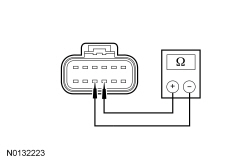 | Yes
GO to BD21 . No GO to BD20 . | ||||||||||||
| BD20 CHECK THE RESISTANCE OF THE DRIVER SEAT BACKREST TED | |||||||||||||
 | Yes
REPAIR circuit CHS01 (GY/VT) or RHS01 (WH/VT) for an open or high resistance. CLEAR the DTCs. REPEAT the self-test. DISCONNECT the battery ground cable. CONNECT driver seat side air bag C367 and passenger seat side air bag C337. REPOWER the SRS . REFER to Section 501-20B . No INSTALL a new driver seat backrest TED . REFER to Seat Backrest Thermo-Electric Device in this section. CLEAR the DTCs. REPEAT the self-test. DISCONNECT the battery ground cable. CONNECT driver seat side air bag C367 and passenger seat side air bag C337. REPOWER the SRS . REFER to Section 501-20B . | ||||||||||||
| BD21 CHECK FOR CORRECT DCSM OPERATION | |||||||||||||
| Yes
INSTALL a new DCSM . REFER to Dual Climate Controlled Seat Module (DCSM) in this section. REPEAT the self-test. TEST the system for normal operation. DISCONNECT the battery ground cable. CONNECT driver seat side air bag C367 and passenger seat side air bag C337. REPOWER the SRS . REFER to Section 501-20B . No The system is operating correctly at this time. The concern may have been caused by a loose or corroded connector. DISCONNECT the battery ground cable. CONNECT driver seat side air bag C367 and passenger seat side air bag C337. REPOWER the SRS . REFER to Section 501-20B . |
Pinpoint Test BE: DTCs B103B and B1111
Refer to Wiring Diagrams Cell 119 , Climate Controlled Seats for schematic and connector information.
The Dual Climate Controlled Seat Module (DCSM) monitors the Thermo-Electric Device (TED) circuits. If a short to ground or voltage on any of these circuits is detected, the DTC(s) will be set.
NOTICE: When taking measurements at Dual Climate Controlled Seat Module (DCSM) harness connectors, do not insert the electrical probes into the female connector pins. Inserting the probes into connector pins can cause intermittent or open electrical connections after reassembly resulting in Diagnostic Trouble Codes (DTCs) and system failure. Touching the tip of these connector pins is recommended instead.
NOTE: The air bag warning indicator illuminates when the correct Restraints Control Module (RCM) fuse is removed and the ignition switch is on.
NOTE: The Supplemental Restraint System (SRS) must be fully operational and free of faults before releasing the vehicle to the customer.
| Test Step | Result / Action to Take | ||||||||||
|---|---|---|---|---|---|---|---|---|---|---|---|
| BE1 CHECK THE TED CIRCUITS FOR A SHORT TO GROUND | |||||||||||
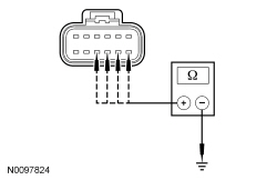 | Yes
GO to BE2 . No If the resistance of C3265A-G, circuit CHS02 (YE/BU) and/or C3265A-H, circuit RHS02 (BU/OG) to ground is not greater than 10,000 ohms to ground, GO to BE6 . If the resistance of C3265A-J, circuit CHS01 (GY/VT) and/or C3265A-K, circuit RHS01 (WH/VT) to ground is not greater than 10,000 ohms to ground, GO to BE7 . | ||||||||||
| BE2 CHECK THE TED CIRCUITS FOR A SHORT TO VOLTAGE | |||||||||||
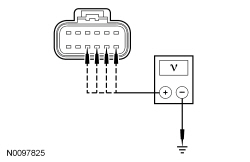 | Yes
If voltage is present at C3265A-G and/or C3265A-H, GO to BE8 . If voltage is present at C3265A-J and/or C3265A-K, GO to BE9 . No GO to BE3 . | ||||||||||
| BE3 CHECK THE RESISTANCE OF THE TED AND WIRING | |||||||||||
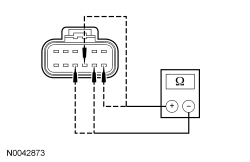 | Yes
INSTALL a new DCSM . REFER to Dual Climate Controlled Seat Module (DCSM) in this section. CLEAR the DTCs. REPEAT the self-test. DISCONNECT the battery ground cable. CONNECT passenger seat side air bag C337 and passenger safety belt buckle C3066. CONNECT driver seat side air bag C367 and driver safety belt buckle C3065. REPOWER the SRS . REFER to Section 501-20B . No If the resistance between DCSM C3265A-G and C3265A-H is not between 0.9 and 10 ohms, GO to BE5 . If the resistance between DCSM C3265A-J and C3265A-K is not between 0.9 and 10 ohms, GO to BE4 . | ||||||||||
| BE4 CHECK THE BACKREST TED RESISTANCE | |||||||||||
 | Yes
REPAIR the circuit(s). CLEAR the DTCs. REPEAT the self-test. DISCONNECT the battery ground cable. CONNECT passenger seat side air bag C337 and passenger safety belt buckle C3066. CONNECT driver seat side air bag C367 and driver safety belt buckle C3065. REPOWER the SRS . REFER to Section 501-20B . No INSTALL a new backrest TED . REFER to Seat Backrest Thermo-Electric Device in this section. CLEAR the DTCs. REPEAT the self-test. DISCONNECT the battery ground cable. CONNECT passenger seat side air bag C337 and passenger safety belt buckle C3066. CONNECT driver seat side air bag C367 and driver safety belt buckle C3065. REPOWER the SRS . REFER to Section 501-20B . | ||||||||||
| BE5 CHECK THE CUSHION TED RESISTANCE | |||||||||||
 | Yes
REPAIR the circuit(s). CLEAR the DTCs. REPEAT the self-test. DISCONNECT the battery ground cable. CONNECT passenger seat side air bag C337 and passenger safety belt buckle C3066. CONNECT driver seat side air bag C367 and driver safety belt buckle C3065. REPOWER the SRS . REFER to Section 501-20B . No INSTALL a new cushion TED . REFER to Seat Cushion Thermo-Electric Device in this section. CLEAR the DTCs. REPEAT the self-test. DISCONNECT the battery ground cable. CONNECT passenger seat side air bag C337 and passenger safety belt buckle C3066. CONNECT driver seat side air bag C367 and driver safety belt buckle C3065. REPOWER the SRS . REFER to Section 501-20B . | ||||||||||
| BE6 CHECK THE CUSHION TED CIRCUITS FOR A SHORT TO GROUND | |||||||||||
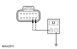 | Yes
INSTALL a new cushion TED . REFER to Seat Cushion Thermo-Electric Device in this section. CLEAR the DTCs. REPEAT the self-test. DISCONNECT the battery ground cable. CONNECT passenger seat side air bag C337 and passenger safety belt buckle C3066. CONNECT driver seat side air bag C367 and driver safety belt buckle C3065. REPOWER the SRS . REFER to Section 501-20B . No REPAIR the circuit(s). CLEAR the DTCs. REPEAT the self-test. DISCONNECT the battery ground cable. CONNECT passenger seat side air bag C337 and passenger safety belt buckle C3066. CONNECT driver seat side air bag C367 and driver safety belt buckle C3065. REPOWER the SRS . REFER to Section 501-20B . | ||||||||||
| BE7 CHECK THE BACKREST TED CIRCUITS FOR A SHORT TO GROUND | |||||||||||
 | Yes
INSTALL a new backrest TED . REFER to Seat Backrest Thermo-Electric Device in this section. CLEAR the DTCs. REPEAT the self-test. DISCONNECT the battery ground cable. CONNECT passenger seat side air bag C337 and passenger safety belt buckle C3066. CONNECT driver seat side air bag C367 and driver safety belt buckle C3065. REPOWER the SRS . REFER to Section 501-20B . No REPAIR the circuit(s). CLEAR the DTCs. REPEAT the self-test. DISCONNECT the battery ground cable. CONNECT passenger seat side air bag C337 and passenger safety belt buckle C3066. CONNECT driver seat side air bag C367 and driver safety belt buckle C3065. REPOWER the SRS . REFER to Section 501-20B . | ||||||||||
| BE8 CHECK THE CUSHION TED CIRCUITS FOR A SHORT TO VOLTAGE | |||||||||||
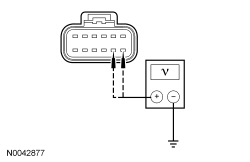 | Yes
REPAIR the circuit(s). CLEAR the DTCs. REPEAT the self-test. DISCONNECT the battery ground cable. CONNECT passenger seat side air bag C337 and passenger safety belt buckle C3066. CONNECT driver seat side air bag C367 and driver safety belt buckle C3065. REPOWER the SRS . REFER to Section 501-20B . No INSTALL a new cushion TED . REFER to Seat Cushion Thermo-Electric Device in this section. CLEAR the DTCs. REPEAT the self-test. DISCONNECT the battery ground cable. CONNECT passenger seat side air bag C337 and passenger safety belt buckle C3066. CONNECT driver seat side air bag C367 and driver safety belt buckle C3065. REPOWER the SRS . REFER to Section 501-20B . | ||||||||||
| BE9 CHECK THE BACKREST TED CIRCUITS FOR A SHORT TO VOLTAGE | |||||||||||
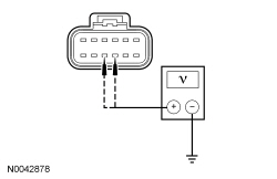 | Yes
REPAIR the circuit(s). CLEAR the DTCs. REPEAT the self-test. DISCONNECT the battery ground cable. CONNECT passenger seat side air bag C337 and passenger safety belt buckle C3066. CONNECT driver seat side air bag C367 and driver safety belt buckle C3065. REPOWER the SRS . REFER to Section 501-20B . No INSTALL a new backrest TED . REFER to Seat Backrest Thermo-Electric Device in this section. CLEAR the DTCs. REPEAT the self-test. DISCONNECT the battery ground cable. CONNECT passenger seat side air bag C337 and passenger safety belt buckle C3066. CONNECT driver seat side air bag C367 and driver safety belt buckle C3065. REPOWER the SRS . REFER to Section 501-20B . |
Pinpoint Test BF: DTC B103C
Refer to Wiring Diagrams Cell 119 , Climate Controlled Seats for schematic and connector information.
The Dual Climate Controlled Seat Module (DCSM) monitors the Thermo-Electric Device (TED) circuits. If an open on any of these circuits is detected, the DTC will be set.
NOTICE: When taking measurements at Dual Climate Controlled Seat Module (DCSM) harness connectors, do not insert the electrical probes into the female connector pins. Inserting the probes into connector pins can cause intermittent or open electrical connections after reassembly resulting in Diagnostic Trouble Codes (DTCs) and system failure. Touching the tip of these connector pins is recommended instead.
NOTE: The air bag warning indicator illuminates when the correct Restraints Control Module (RCM) fuse is removed and the ignition switch is on.
NOTE: The Supplemental Restraint System (SRS) must be fully operational and free of faults before releasing the vehicle to the customer.
| Test Step | Result / Action to Take | |||||||||||||||
|---|---|---|---|---|---|---|---|---|---|---|---|---|---|---|---|---|
| BF1 CHECK THE TED CIRCUITS FOR AN OPEN | ||||||||||||||||
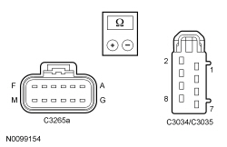 | Yes
GO to BF2 . No REPAIR the circuit(s). CLEAR the DTCs. REPEAT the self-test. DISCONNECT the battery ground cable. CONNECT passenger seat side air bag C337 and passenger safety belt buckle C3066. CONNECT driver seat side air bag C367 and driver safety belt buckle C3065. REPOWER the SRS . REFER to Section 501-20B . | |||||||||||||||
| BF2 CHECK THE TED CIRCUITS FOR A SHORT TO VOLTAGE | ||||||||||||||||
 | Yes
REPAIR the circuit(s). CLEAR the DTCs. REPEAT the self-test. DISCONNECT the battery ground cable. CONNECT passenger seat side air bag C337 and passenger safety belt buckle C3066. CONNECT driver seat side air bag C367 and driver safety belt buckle C3065. REPOWER the SRS . REFER to Section 501-20B . No GO to BF3 . | |||||||||||||||
| BF3 CHECK THE BACKREST AND CUSHION TED RESISTANCE | ||||||||||||||||
 | Yes
INSTALL a new DCSM . REFER to Dual Climate Controlled Seat Module (DCSM) in this section. CLEAR the DTCs. REPEAT the self-test. DISCONNECT the battery ground cable. CONNECT passenger seat side air bag C337 and passenger safety belt buckle C3066. CONNECT driver seat side air bag C367 and driver safety belt buckle C3065. REPOWER the SRS . REFER to Section 501-20B . No If backrest TED resistance is not between 0.9 and 10 ohms, INSTALL a new backrest TED . REFER to Seat Backrest Thermo-Electric Device in this section. CLEAR the DTCs. REPEAT the self-test. If cushion TED resistance is not between 0.9 and 10 ohms, INSTALL a new cushion TED . REFER to Seat Cushion Thermo-Electric Device in this section. CLEAR the DTCs. REPEAT the self-test. DISCONNECT the battery ground cable. CONNECT passenger seat side air bag C337 and passenger safety belt buckle C3066. CONNECT driver seat side air bag C367 and driver safety belt buckle C3065. REPOWER the SRS . REFER to Section 501-20B . |
Pinpoint Test BG: DTC B103D
Refer to Wiring Diagrams Cell 119 , Climate Controlled Seats for schematic and connector information.
The Dual Climate Controlled Seat Module (DCSM) is supplied voltage at all times, but the climate controlled seat system only operates with the engine running. The system can be operated with the ignition ON engine OFF by using a scan tool to bypass the climate controlled seat switches on the touchscreen interface. When commanding a heat or cool mode operation in this manner, the climate controlled seat system only operates in 15 second intervals. Both voltage supply circuits are spliced together internal to the DCSM , so if one circuit becomes open, both seats can still be operated. However, if a fault occurs setting a DTC specific to either climate controlled seat, only the affected seat is disabled by the DCSM .
The seat cushion is equipped with a Thermo-Electric Device (TED) assembly that includes a seat blower (fan motor, serviced as an assembly with the TED ). Similarly, the seat backrest is also equipped with its own TED assembly with blower. Cabin air is drawn through the blower and distributed to each of the TED modules located in the seat cushion and backrest. The TEDs then heat or cool the air. The air is then directed into the foam pad and manifold where it is distributed along the surface of the cushion and backrest of the seat. Once the system is activated, the DCSM uses a set of flexible algorithms to control the heating/cooling modes and the blower speed dependant on the commanded climate controlled seat settings.
NOTICE: When taking measurements at Dual Climate Controlled Seat Module (DCSM) harness connectors, do not insert the electrical probes into the female connector pins. Inserting the probes into connector pins can cause intermittent or open electrical connections after reassembly resulting in Diagnostic Trouble Codes (DTCs) and system failure. Touching the tip of these connector pins is recommended instead.
NOTE: The air bag warning indicator illuminates when the correct Restraints Control Module (RCM) fuse is removed and the ignition switch is on.
NOTE: The Supplemental Restraint System (SRS) must be fully operational and free of faults before releasing the vehicle to the customer.
| Test Step | Result / Action to Take |
|---|---|
| BG1 CHECK THE BLOWER MOTOR FEED CIRCUIT FOR A SHORT TO GROUND | |
 | Yes
GO to BG2 . No REPAIR the circuit. CLEAR the DTCs. REPEAT the self-test. DISCONNECT the battery ground cable. CONNECT passenger seat side air bag C337 and passenger safety belt buckle C3066. CONNECT driver seat side air bag C367 and driver safety belt buckle C3065. REPOWER the SRS . REFER to Section 501-20B . |
| BG2 CHECK FOR A SHORT BETWEEN THE BLOWER MOTOR FEED AND GROUND CIRCUITS | |
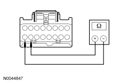 | Yes
GO to BG3 . No REPAIR the circuits. CLEAR the DTCs. REPEAT the self-test. DISCONNECT the battery ground cable. CONNECT passenger seat side air bag C337 and passenger safety belt buckle C3066. CONNECT driver seat side air bag C367 and driver safety belt buckle C3065. REPOWER the SRS . REFER to Section 501-20B . |
| BG3 CHECK THE BACKREST AND CUSHION BLOWER MOTOR RESISTANCE | |
 | Yes
INSTALL a new DCSM . REFER to Dual Climate Controlled Seat Module (DCSM) in this section. CLEAR the DTCs. REPEAT the self-test. DISCONNECT the battery ground cable. CONNECT passenger seat side air bag C337 and passenger safety belt buckle C3066. CONNECT driver seat side air bag C367 and driver safety belt buckle C3065. REPOWER the SRS . REFER to Section 501-20B . No If cushion TED resistance is not between 4,000 and 10,000 ohms, INSTALL a new cushion TED . REFER to Seat Cushion Thermo-Electric Device in this section. CLEAR the DTCs. REPEAT the self-test. If backrest TED resistance is not between 4,000 and 10,000 ohms, INSTALL a new backrest TED . REFER to Seat Backrest Thermo-Electric Device in this section. CLEAR the DTCs. REPEAT the self-test. DISCONNECT the battery ground cable. CONNECT passenger seat side air bag C337 and passenger safety belt buckle C3066. CONNECT driver seat side air bag C367 and driver safety belt buckle C3065. REPOWER the SRS . REFER to Section 501-20B . |
Pinpoint Test BH: DTCs B1113 and B111B
Refer to Wiring Diagrams Cell 119 , Climate Controlled Seats for schematic and connector information.
The seat cushion and backrest are equipped with a Thermo-Electric Device (TED) assembly that includes a seat blower (fan motor, serviced as an assembly with the TED ). When the Dual Climate Controlled Seat Module (DCSM) detects an overcurrent and/or overtemperature in the output circuits to the TEDs , it disables the affected seat and sets the following DTCs:
NOTICE: When taking measurements at Dual Climate Controlled Seat Module (DCSM) harness connectors, do not insert the electrical probes into the female connector pins. Inserting the probes into connector pins can cause intermittent or open electrical connections after reassembly resulting in Diagnostic Trouble Codes (DTCs) and system failure. Touching the tip of these connector pins is recommended instead.
NOTE: The air bag warning indicator illuminates when the correct Restraints Control Module (RCM) fuse is removed and the ignition switch is on.
NOTE: The Supplemental Restraint System (SRS) must be fully operational and free of faults before releasing the vehicle to the customer.
| Test Step | Result / Action to Take | ||||||||||
|---|---|---|---|---|---|---|---|---|---|---|---|
| BH1 CHECK THE TED CIRCUITS FOR A SHORT TO GROUND | |||||||||||
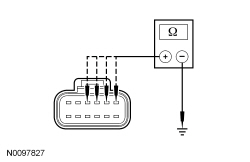 | Yes
GO to BH2 . No If the resistance between C3265A-A and/or C3265A-B to ground is not greater than 10,000 ohms, GO to BH6 . If the resistance between C3265A-C and/or C3265A-D to ground is not greater than 10,000 ohms, GO to BH7 . | ||||||||||
| BH2 CHECK THE TED CIRCUITS FOR A SHORT TO VOLTAGE | |||||||||||
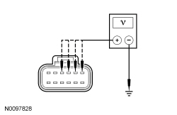 | Yes
If voltage is present at C3265A-A and/or C3265A-B, GO to BH8 . If voltage is present at C3265A-C and/or C3265A-D, GO to BH9 . No GO to BH3 . | ||||||||||
| BH3 CHECK THE RESISTANCE OF THE TED AND WIRING | |||||||||||
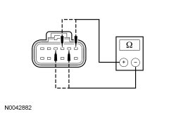 | Yes
INSTALL a new DCSM . REFER to Dual Climate Controlled Seat Module (DCSM) in this section. CLEAR the DTCs. REPEAT the self-test. DISCONNECT the battery ground cable. CONNECT passenger seat side air bag C337 and passenger safety belt buckle C3066. REPOWER the SRS . REFER to Section 501-20B . No If the resistance between DCSM C3265A-A and C3265A-B is not between 0.9 and 10 ohms, GO to BH5 . If the resistance between DCSM C3265A-C and C3265A-D is not between 0.9 and 10 ohms, GO to BH4 . | ||||||||||
| BH4 CHECK THE BACKREST TED RESISTANCE | |||||||||||
 | Yes
REPAIR the circuit(s). CLEAR the DTCs. REPEAT the self-test. DISCONNECT the battery ground cable. CONNECT passenger seat side air bag C337 and passenger safety belt buckle C3066. REPOWER the SRS . REFER to Section 501-20B . No INSTALL a new backrest TED . REFER to Seat Backrest Thermo-Electric Device in this section. CLEAR the DTCs. REPEAT the self-test. DISCONNECT the battery ground cable. CONNECT passenger seat side air bag C337 and passenger safety belt buckle C3066. REPOWER the SRS . REFER to Section 501-20B . | ||||||||||
| BH5 CHECK THE CUSHION TED RESISTANCE | |||||||||||
 | Yes
REPAIR the circuit(s). CLEAR the DTCs. REPEAT the self-test. DISCONNECT the battery ground cable. CONNECT passenger seat side air bag C337 and passenger safety belt buckle C3066. REPOWER the SRS . REFER to Section 501-20B . No INSTALL a new cushion TED . REFER to Seat Cushion Thermo-Electric Device in this section. CLEAR the DTCs. REPEAT the self-test. DISCONNECT the battery ground cable. CONNECT passenger seat side air bag C337 and passenger safety belt buckle C3066. REPOWER the SRS . REFER to Section 501-20B . | ||||||||||
| BH6 CHECK THE CUSHION TED CIRCUITS FOR A SHORT TO GROUND | |||||||||||
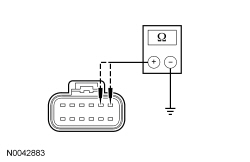 | Yes
INSTALL a new cushion TED . REFER to Seat Cushion Thermo-Electric Device in this section. CLEAR the DTCs. REPEAT the self-test. DISCONNECT the battery ground cable. CONNECT passenger seat side air bag C337 and passenger safety belt buckle C3066. REPOWER the SRS . REFER to Section 501-20B . No REPAIR the circuit(s). CLEAR the DTCs. REPEAT the self-test. DISCONNECT the battery ground cable. CONNECT passenger seat side air bag C337 and passenger safety belt buckle C3066. REPOWER the SRS . REFER to Section 501-20B . | ||||||||||
| BH7 CHECK THE BACKREST TED CIRCUITS FOR A SHORT TO GROUND | |||||||||||
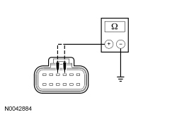 | Yes
INSTALL a new backrest TED . REFER to Seat Backrest Thermo-Electric Device in this section. CLEAR the DTCs. REPEAT the self-test. DISCONNECT the battery ground cable. CONNECT passenger seat side air bag C337 and passenger safety belt buckle C3066. REPOWER the SRS . REFER to Section 501-20B . No REPAIR the circuit(s). CLEAR the DTCs. REPEAT the self-test. DISCONNECT the battery ground cable. CONNECT passenger seat side air bag C337 and passenger safety belt buckle C3066. REPOWER the SRS . REFER to Section 501-20B . | ||||||||||
| BH8 CHECK THE CUSHION TED CIRCUITS FOR A SHORT TO VOLTAGE | |||||||||||
 | Yes
REPAIR the circuit(s). CLEAR the DTCs. REPEAT the self-test. DISCONNECT the battery ground cable. CONNECT passenger seat side air bag C337 and passenger safety belt buckle C3066. REPOWER the SRS . REFER to Section 501-20B . No INSTALL a new cushion TED . REFER to Seat Cushion Thermo-Electric Device in this section. CLEAR the DTCs. REPEAT the self-test. DISCONNECT the battery ground cable. CONNECT passenger seat side air bag C337 and passenger safety belt buckle C3066. REPOWER the SRS . REFER to Section 501-20B . | ||||||||||
| BH9 CHECK THE BACKREST TED CIRCUITS FOR A SHORT TO VOLTAGE | |||||||||||
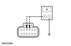 | Yes
REPAIR the circuit(s). CLEAR the DTCs. REPEAT the self-test. DISCONNECT the battery ground cable. CONNECT passenger seat side air bag C337 and passenger safety belt buckle C3066. REPOWER the SRS . REFER to Section 501-20B . No INSTALL a new backrest TED . REFER to Seat Backrest Thermo-Electric Device in this section. CLEAR the DTCs. REPEAT the self-test. DISCONNECT the battery ground cable. CONNECT passenger seat side air bag C337 and passenger safety belt buckle C3066. REPOWER the SRS . REFER to Section 501-20B . |
Pinpoint Test BI: DTC B111C
Refer to Wiring Diagrams Cell 119 , Climate Controlled Seats for schematic and connector information.
The seat cushion and backrest are equipped with a Thermo-Electric Device (TED) assembly that includes a seat blower (fan motor, serviced as an assembly with the TED ). If the Dual Climate Controlled Seat Module (DCSM) detects an open circuit or high TED resistance, the following DTC sets:
NOTICE: When taking measurements at Dual Climate Controlled Seat Module (DCSM) harness connectors, do not insert the electrical probes into the female connector pins. Inserting the probes into connector pins can cause intermittent or open electrical connections after reassembly resulting in Diagnostic Trouble Codes (DTCs) and system failure. Touching the tip of these connector pins is recommended instead.
NOTE: The air bag warning indicator illuminates when the correct Restraints Control Module (RCM) fuse is removed and the ignition switch is on.
NOTE: The Supplemental Restraint System (SRS) must be fully operational and free of faults before releasing the vehicle to the customer.
| Test Step | Result / Action to Take | |||||||||||||||
|---|---|---|---|---|---|---|---|---|---|---|---|---|---|---|---|---|
| BI1 CHECK THE TED CIRCUITS FOR AN OPEN | ||||||||||||||||
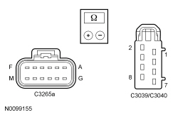 | Yes
GO to BI2 . No REPAIR the circuit(s). CLEAR the DTCs. REPEAT the self-test. DISCONNECT the battery ground cable. CONNECT passenger seat side air bag C337 and passenger safety belt buckle C3066. REPOWER the SRS . REFER to Section 501-20B . | |||||||||||||||
| BI2 CHECK THE TED CIRCUITS FOR A SHORT TO VOLTAGE | ||||||||||||||||
 | Yes
REPAIR the circuit(s). CLEAR the DTCs. REPEAT the self-test. DISCONNECT the battery ground cable. CONNECT passenger seat side air bag C337 and passenger safety belt buckle C3066. REPOWER the SRS . REFER to Section 501-20B . No GO to BI3 . | |||||||||||||||
| BI3 CHECK THE BACKREST AND CUSHION TED RESISTANCE | ||||||||||||||||
 | Yes
INSTALL a new DCSM . REFER to Dual Climate Controlled Seat Module (DCSM) in this section. CLEAR the DTCs. REPEAT the self-test. DISCONNECT the battery ground cable. CONNECT passenger seat side air bag C337 and passenger safety belt buckle C3066. REPOWER the SRS . REFER to Section 501-20B . No If backrest TED resistance is not between 0.9 and 10 ohms, INSTALL a new backrest TED . REFER to Seat Backrest Thermo-Electric Device in this section. CLEAR the DTCs. REPEAT the self-test. If cushion TED resistance is not between 0.9 and 10 ohms, INSTALL a new cushion TED . REFER to Seat Cushion Thermo-Electric Device in this section. CLEAR the DTCs. REPEAT the self-test. DISCONNECT the battery ground cable. CONNECT passenger seat side air bag C337 and passenger safety belt buckle C3066. REPOWER the SRS . REFER to Section 501-20B . |
Pinpoint Test BJ: DTC B111D
Refer to Wiring Diagrams Cell 119 , Climate Controlled Seats for schematic and connector information.
The Dual Climate Controlled Seat Module (DCSM) is supplied voltage at all times, but the climate controlled seat system only operates with the engine running. The system can be operated with the ignition ON engine OFF by using a scan tool to bypass the climate controlled seat buttons on the touchscreen interface. When commanding a heat or cool mode operation in this manner, the climate controlled seat system only operates in 15 second intervals. Both voltage supply circuits are spliced together internal to the DCSM , so if one circuit becomes open, both seats can still be operated. However, if a fault occurs setting a DTC specific to either climate controlled seat, only the affected seat is disabled by the DCSM .
The seat cushion is equipped with a Thermo-Electric Device (TED) assembly that includes a seat blower (fan motor, serviced as an assembly with the TED ). Similarly, the seat backrest is also equipped with its own TED assembly with blower. Cabin air is drawn through the blower and distributed to each of the TED modules located in the seat cushion and backrest. The TEDs then heat or cool the air. The air is then directed into the foam pad and manifold where it is distributed along the surface of the cushion and backrest of the seat. Once the system is activated, the DCSM uses a set of flexible algorithms to control the heating/cooling modes and the blower speed dependant on the commanded climate controlled seat settings.
NOTICE: When taking measurements at Dual Climate Controlled Seat Module (DCSM) harness connectors, do not insert the electrical probes into the female connector pins. Inserting the probes into connector pins can cause intermittent or open electrical connections after reassembly resulting in Diagnostic Trouble Codes (DTCs) and system failure. Touching the tip of these connector pins is recommended instead.
NOTE: The air bag warning indicator illuminates when the correct Restraints Control Module (RCM) fuse is removed and the ignition switch is on.
NOTE: The Supplemental Restraint System (SRS) must be fully operational and free of faults before releasing the vehicle to the customer.
| Test Step | Result / Action to Take |
|---|---|
| BJ1 CHECK THE BLOWER MOTOR FEED CIRCUIT FOR A SHORT TO GROUND | |
 | Yes
GO to BJ2 . No REPAIR the circuit. REPEAT the self-test. DISCONNECT the battery ground cable. CONNECT passenger seat side air bag C337 and passenger safety belt buckle C3066. REPOWER the SRS . REFER to Section 501-20B . |
| BJ2 CHECK FOR A SHORT BETWEEN THE BLOWER MOTOR FEED AND GROUND CIRCUITS | |
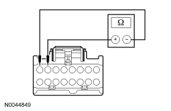 | Yes
GO to BJ3 . No REPAIR the circuits. CLEAR the DTCs. REPEAT the self-test. DISCONNECT the battery ground cable. CONNECT passenger seat side air bag C337 and passenger safety belt buckle C3066. REPOWER the SRS . REFER to Section 501-20B . |
| BJ3 CHECK THE BACKREST CUSHION BLOWER MOTOR RESISTANCE | |
 | Yes
INSTALL a new DCSM . REFER to Dual Climate Controlled Seat Module (DCSM) in this section. CLEAR the DTCs. REPEAT the self-test. DISCONNECT the battery ground cable. CONNECT passenger seat side air bag C337 and passenger safety belt buckle C3066. REPOWER the SRS . REFER to Section 501-20B . No If cushion TED resistance is not between 4,000 and 10,000 ohms, INSTALL a new cushion TED . REFER to Seat Cushion Thermo-Electric Device in this section. CLEAR the DTCs. REPEAT the self-test. If backrest TED resistance is not between 4,000 and 10,000 ohms, INSTALL a new backrest TED . REFER to Seat Backrest Thermo-Electric Device in this section. CLEAR the DTCs. REPEAT the self-test. DISCONNECT the battery ground cable. CONNECT passenger seat side air bag C337 and passenger safety belt buckle C3066. REPOWER the SRS . REFER to Section 501-20B . |
Pinpoint Test BK: DTC B19A1
Refer to Wiring Diagrams Cell 119 , Climate Controlled Seats for schematic and connector information.
The Dual Climate Controlled Seat Module (DCSM) supplies voltage and ground to the passenger seat cushion Thermo-Electric Device (TED). The DCSM also sends a speed control voltage signal to the TED to control blower speed.
NOTICE: When taking measurements at Dual Climate Controlled Seat Module (DCSM) harness connectors, do not insert the electrical probes into the female connector pins. Inserting the probes into connector pins can cause intermittent or open electrical connections after reassembly resulting in Diagnostic Trouble Codes (DTCs) and system failure. Touching the tip of these connector pins is recommended instead.
NOTE: The air bag warning indicator illuminates when the correct Restraints Control Module (RCM) fuse is removed and the ignition switch is on.
NOTE: The Supplemental Restraint System (SRS) must be fully operational and free of faults before releasing the vehicle to the customer.
| Test Step | Result / Action to Take |
|---|---|
| BK1 CHECK THE CUSHION TED BLOWER MOTOR SPEED CONTROL CIRCUIT FOR A SHORT TO VOLTAGE | |
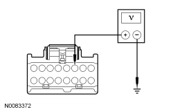 | Yes
GO to BK2 . No GO to BK3 . |
| BK2 CHECK THE CUSHION TED BLOWER MOTOR SPEED CONTROL CIRCUIT FOR A SHORT TO VOLTAGE | |
 | Yes
REPAIR the circuit. CLEAR the DTCs. REPEAT the self-test. DISCONNECT the battery ground cable. CONNECT passenger seat side air bag C337 and passenger safety belt buckle C3066. REPOWER the SRS . REFER to Section 501-20B . No GO to BK3 . |
| BK3 CHECK THE CUSHION TED BLOWER MOTOR SPEED CONTROL AND BLOWER MOTOR FEED CIRCUITS FOR A SHORT TOGETHER | |
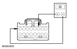 | Yes
GO to BK4 . No REPAIR the circuits. CLEAR the DTCs. REPEAT the self-test. DISCONNECT the battery ground cable. CONNECT passenger seat side air bag C337 and passenger safety belt buckle C3066. REPOWER the SRS . REFER to Section 501-20B . |
| BK4 CHECK THE CUSHION TED RESISTANCE FOR AN INTERNAL SHORT | |
 | Yes
INSTALL a new DCSM . REFER to Dual Climate Controlled Seat Module (DCSM) in this section. CLEAR the DTCs. REPEAT the self-test. DISCONNECT the battery ground cable. CONNECT passenger seat side air bag C337 and passenger safety belt buckle C3066. REPOWER the SRS . REFER to Section 501-20B . No INSTALL a new cushion TED . REFER to Seat Cushion Thermo-Electric Device in this section. CLEAR the DTCs. REPEAT the self-test. DISCONNECT the battery ground cable. CONNECT passenger seat side air bag C337 and passenger safety belt buckle C3066. REPOWER the SRS . REFER to Section 501-20B . |
Pinpoint Test BL: DTC B19A2
Refer to Wiring Diagrams Cell 119 , Climate Controlled Seats for schematic and connector information.
The Dual Climate Controlled Seat Module (DCSM) supplies voltage and ground to the passenger seat backrest Thermo-Electric Device (TED). The DCSM also sends a speed control voltage signal to the TED to control blower speed.
NOTICE: When taking measurements at Dual Climate Controlled Seat Module (DCSM) harness connectors, do not insert the electrical probes into the female connector pins. Inserting the probes into connector pins can cause intermittent or open electrical connections after reassembly resulting in Diagnostic Trouble Codes (DTCs) and system failure. Touching the tip of these connector pins is recommended instead.
NOTE: The air bag warning indicator illuminates when the correct Restraints Control Module (RCM) fuse is removed and the ignition switch is on.
NOTE: The Supplemental Restraint System (SRS) must be fully operational and free of faults before releasing the vehicle to the customer.
| Test Step | Result / Action to Take |
|---|---|
| BL1 CHECK THE BACKREST TED BLOWER MOTOR SPEED CONTROL CIRCUIT FOR A SHORT TO VOLTAGE | |
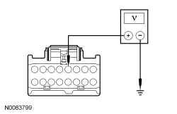 | Yes
GO to BL2 . No GO to BL3 . |
| BL2 CHECK THE BACKREST TED BLOWER MOTOR SPEED CONTROL CIRCUIT FOR A SHORT TO VOLTAGE | |
 | Yes
REPAIR the circuit. CLEAR the DTCs. REPEAT the self-test. DISCONNECT the battery ground cable. CONNECT passenger seat side air bag C337 and passenger safety belt buckle C3066. REPOWER the SRS . REFER to Section 501-20B . No GO to BL3 . |
| BL3 CHECK THE BACKREST TED BLOWER MOTOR SPEED CONTROL AND BLOWER MOTOR FEED CIRCUITS FOR A SHORT TOGETHER | |
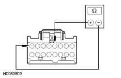 | Yes
GO to BL4 . No REPAIR the circuits. CLEAR the DTCs. REPEAT the self-test. DISCONNECT the battery ground cable. CONNECT passenger seat side air bag C337 and passenger safety belt buckle C3066. REPOWER the SRS . REFER to Section 501-20B . |
| BL4 CHECK THE BACKREST TED RESISTANCE FOR AN INTERNAL SHORT | |
 | Yes
INSTALL a new DCSM . REFER to Dual Climate Controlled Seat Module (DCSM) in this section. CLEAR the DTCs. REPEAT the self-test. DISCONNECT the battery ground cable. CONNECT passenger seat side air bag C337 and passenger safety belt buckle C3066. REPOWER the SRS . REFER to Section 501-20B . No INSTALL a new backrest TED . REFER to Seat Backrest Thermo-Electric Device in this section. CLEAR the DTCs. REPEAT the self-test. DISCONNECT the battery ground cable. CONNECT passenger seat side air bag C337 and passenger safety belt buckle C3066. REPOWER the SRS . REFER to Section 501-20B . |
Pinpoint Test BM: DTC B19A3
Refer to Wiring Diagrams Cell 119 , Climate Controlled Seats for schematic and connector information.
The Dual Climate Controlled Seat Module (DCSM) supplies voltage and ground to the driver seat cushion Thermo-Electric Device (TED). The DCSM also sends a speed control voltage signal to the TED to control blower speed.
NOTICE: When taking measurements at Dual Climate Controlled Seat Module (DCSM) harness connectors, do not insert the electrical probes into the female connector pins. Inserting the probes into connector pins can cause intermittent or open electrical connections after reassembly resulting in Diagnostic Trouble Codes (DTCs) and system failure. Touching the tip of these connector pins is recommended instead.
NOTE: The air bag warning indicator illuminates when the correct Restraints Control Module (RCM) fuse is removed and the ignition switch is on.
NOTE: The Supplemental Restraint System (SRS) must be fully operational and free of faults before releasing the vehicle to the customer.
| Test Step | Result / Action to Take |
|---|---|
| BM1 CHECK THE CUSHION TED BLOWER MOTOR SPEED CONTROL CIRCUIT FOR A SHORT TO VOLTAGE | |
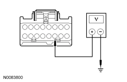 | Yes
GO to BM2 . No GO to BM3 . |
| BM2 CHECK THE CUSHION TED BLOWER MOTOR SPEED CONTROL CIRCUIT FOR A SHORT TO VOLTAGE | |
 | Yes
REPAIR the circuit. CLEAR the DTCs. REPEAT the self-test. DISCONNECT the battery ground cable. CONNECT passenger seat side air bag C337 and passenger safety belt buckle C3066. CONNECT driver seat side air bag C367 and driver safety belt buckle C3065. REPOWER the SRS . REFER to Section 501-20B . No GO to BM3 . |
| BM3 CHECK THE CUSHION TED BLOWER MOTOR SPEED CONTROL AND BLOWER MOTOR FEED CIRCUITS FOR A SHORT TOGETHER | |
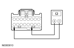 | Yes
GO to BM4 . No REPAIR the circuits. CLEAR the DTCs. REPEAT the self-test. DISCONNECT the battery ground cable. CONNECT passenger seat side air bag C337 and passenger safety belt buckle C3066. CONNECT driver seat side air bag C367 and driver safety belt buckle C3065. REPOWER the SRS . REFER to Section 501-20B . |
| BM4 CHECK THE CUSHION TED RESISTANCE FOR AN INTERNAL SHORT | |
 | Yes
INSTALL a new DCSM . REFER to Dual Climate Controlled Seat Module (DCSM) in this section. CLEAR the DTCs. REPEAT the self-test. DISCONNECT the battery ground cable. CONNECT passenger seat side air bag C337 and passenger safety belt buckle C3066. CONNECT driver seat side air bag C367 and driver safety belt buckle C3065. REPOWER the SRS . REFER to Section 501-20B . No INSTALL a new cushion TED . REFER to Seat Cushion Thermo-Electric Device in this section. CLEAR the DTCs. REPEAT the self-test. DISCONNECT the battery ground cable. CONNECT passenger seat side air bag C337 and passenger safety belt buckle C3066. CONNECT driver seat side air bag C367 and driver safety belt buckle C3065. REPOWER the SRS . REFER to Section 501-20B . |
Pinpoint Test BN: A Single Climate Controlled Seat is Inoperative
Refer to Wiring Diagrams Cell 119 , Climate Controlled Seats for schematic and connector information.
The Dual Climate Controlled Seat Module (DCSM) is supplied voltage at all times, but the climate controlled seat system only operates with the engine running. The system can be operated with the ignition ON engine OFF by using a scan tool to bypass the climate controlled seat buttons on the touchscreen interface. When commanding a heat or cool mode operation in this manner, it only operates in 15 second intervals. Both voltage supply circuits are spliced together internal to the DCSM , so if one circuit becomes open, both seats can still be operated. However, if a fault occurs setting a DTC specific to either climate controlled seat, only the affected seat is disabled by the DCSM .
When the climate control seat buttons are activated on the touchscreen interface, the APIM sends the climate controlled seat commands to the Front Controls Interface Module (FCIM) using the I-CAN . The FCIM sends the request message to the IPC using the I-CAN . The IPC sends the request message to the BCM over the HS-CAN . Finally the BCM sends the communicates climate controlled seat commands to the DCSM using the MS-CAN .
NOTICE: When taking measurements at Dual Climate Controlled Seat Module (DCSM) harness connectors, do not insert the electrical probes into the female connector pins. Inserting the probes into connector pins can cause intermittent or open electrical connections after reassembly resulting in Diagnostic Trouble Codes (DTCs) and system failure. Touching the tip of these connector pins is recommended instead.
| Test Step | Result / Action to Take |
|---|---|
| BN1 CHECK OPERATION OF BOTH CLIMATE CONTROLLED SEATS AND VERIFY THE SYMPTOM | |
| Yes
GO to BN2 . No If both seats are inoperative, GO to Symptom Chart . |
| BN2 CHECK FOR DCSM DTCs | |
| Yes
GO to the Dual Climate Controlled Seat Module (DCSM) DTC Chart. No GO to BN3 . |
| BN3 CHECK OPERATION OF THE DCSM USING PIDs | |
NOTE: The purpose of this step is to verify the DCSM is able to receive and process inbound command messages from the network and demonstrate if the DCSM is operational. This indicates the FCIM may not be sending the commands correctly.
| Yes
GO to BN4 . No INSTALL a new DCSM . REFER to Dual Climate Controlled Seat Module (DCSM) in this section. REPEAT the self-test. |
| BN4 USE THE TOUCHSCREEN BUTTONS AND MONITOR THE DCSM PID FOR A RESPONSE | |
| Yes
If the fault is intermittent, CHECK for causes of the intermittent fault. INSPECT the connectors, terminals and wiring. ATTEMPT to recreate the fault by flexing the wire harness and operating the system. CHECK the electrical connectors for corrosion, poor pin contact or pushed-out pins. REPAIR any intermittent concerns found and TIGHTEN any loose DCSM connector pins. CLEAR the DTCs. REPEAT the self-test. No REFER to Section 415-00B or Section 415-00C to diagnose the inoperative touchscreen button(s). TEST the system for normal operation. |